Is there a fast way to tell a toolpath to overcut on a dado to avoid the tool radius on the ends?
Open to using Create, Vectric or something else if it can handle it and DXF imports.
Need to do some cabinet runs so have full 4x8 sheets that have a lot of dado’s so manually editing all the nodes/points is not ideal to make the tool overrun and cut a clean dado.
If you’re going to edit rectangles to add dogbones, it would be just as quick to edit them & make them 1" longer (1/2" on each end to let your 3/4" cutter extend past it’s 3/8" radius). Or less if you’re using a smaller tool.
I’m not finding the dogbone option in the program anywhere. Unless i’m just misunderstanding what that is.
Editing the rectangles might have to be the option, it’s just a lot dado’s per sheet, and I have a lot of cabinets to build.
I’ve been going back and forth between Create Pro and Vectric to figure out which one makes the most sense, if i can do everything in Create Pro, then that’s the one i’ll buy.
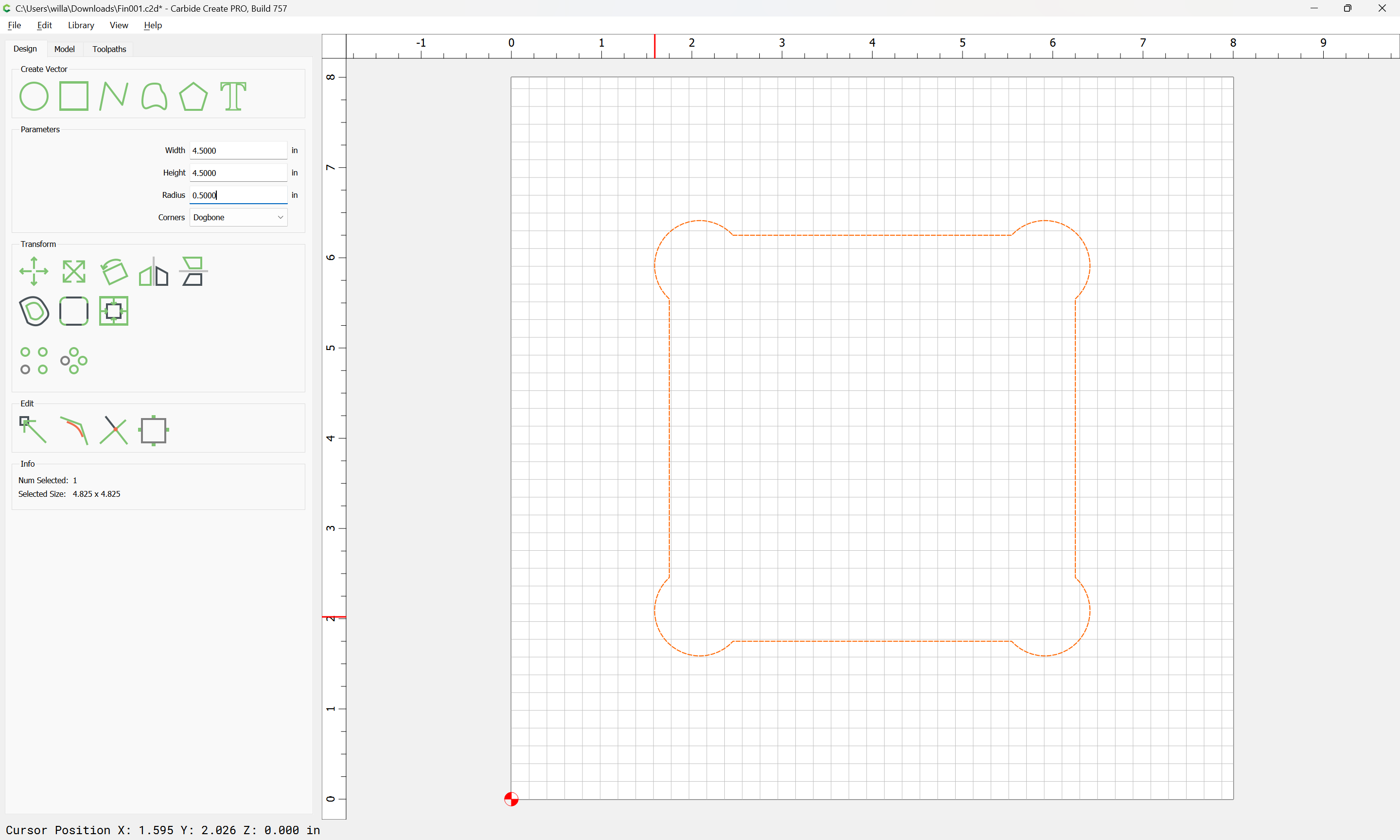
You can add them pretty quickly by snapping in a circle of the correct size, then using the “Trim Vectors” command to delete what isn’t needed, then closing things up selecting them and choosing “Join Vectors”.
The cabinet design is all done in Moziak, they do support CNC and generating Gcode, but there is no post process for Carbide. So my option is to export out layered DXF’s. That’s another issue i’m seeing with Create is layered DXF’s aren’t supported (i submitted a feature request). Why that matters is the various components of the cabinets on are each layer, the core cabinet cutout is on one, the dado’s are on another and the holes for shelves etc are another layer.
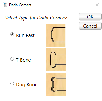
You can choose what type of dado cut you want in Mozaik, but that affects the generated Gcode, and not the DXF drawing as those are exact cabinet dimensions, you can export those for a panel saw, table saw or manual assembly for example.
Let me switch computers and grab a few screenshots.
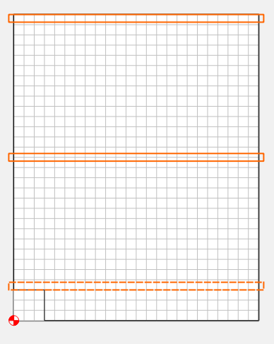
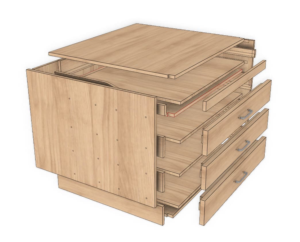
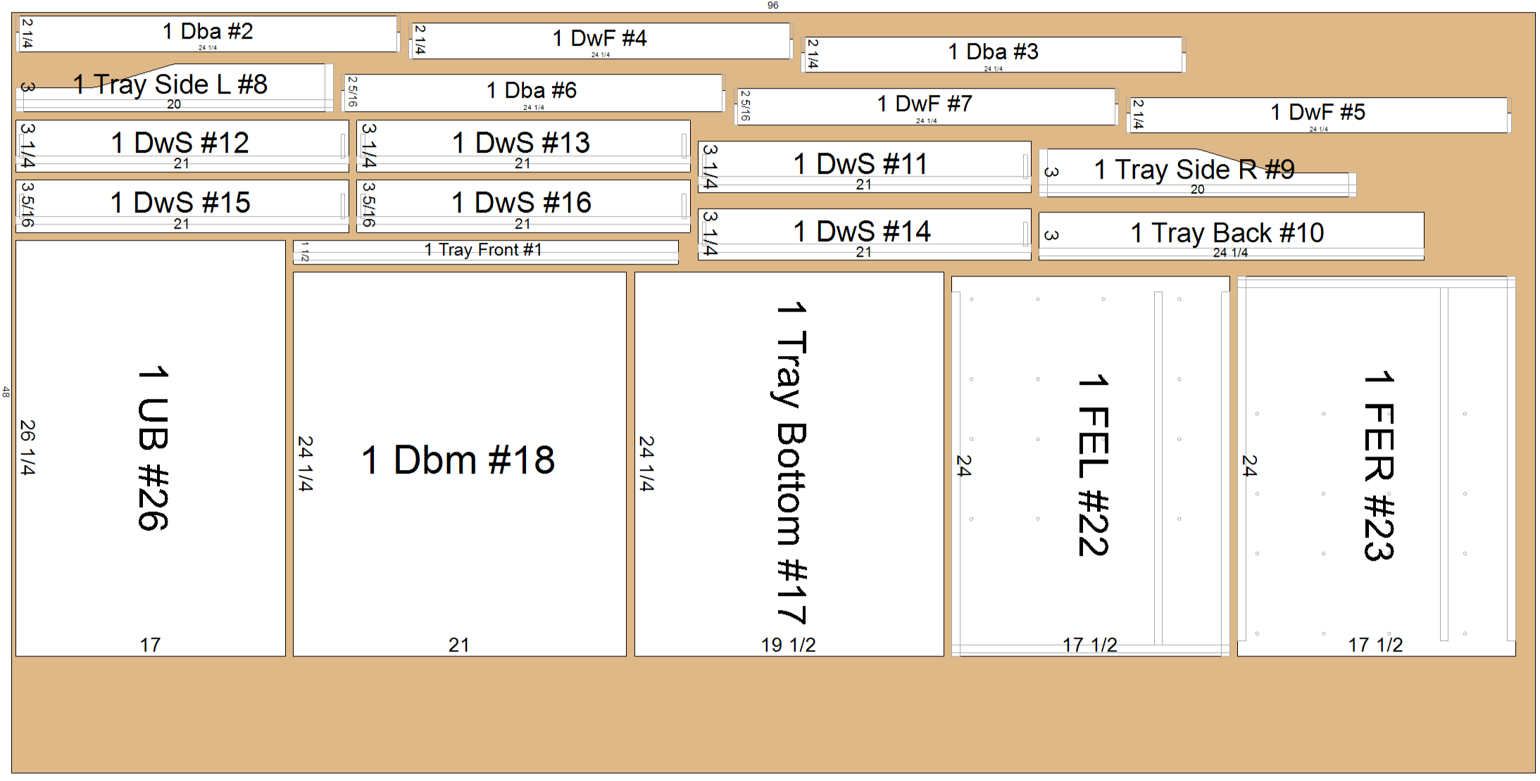
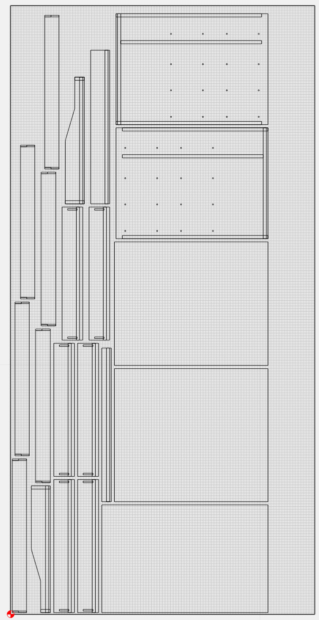
Here is a sample cabinet, this is a 3 drawer with pull out tray. For exmaple this will go under my CNC and the pull out try is for the laptop. The cabinet and drawers are all dado.
I gotta believe one of the posts they have (out of over 100) will support your machine. Any of those other machines that use a GRBL controller should work. And Mosaik says they will help you…
If you are thinking of purchasing a machine not on this list, email us at cncpost@mozaiksoftware.com to ensure our current post processors will support that model year or to see if a post can be created for the machine. Please attach a working GCode file.*
Your G-Code pretty much just needs a G90 (Absolute) G20 (Inch - or G21 for metric), Toolchange (M05, M6T###), and Spindle (M03S18000) command, and a M02 or M30 at the end of program.
They say to “Include a working program”. Here’s a really simple example
That particular sheet is mostly the drawer components yes.
The G-code is beyond me, i just don’t know that stuff. But i will try and contact them and see if i get anywhere for the sake of it. They don’t support tiling though, so that’s another issue since the Pro 5 is only a 4x4 bed and they are expecting things to be 4x8. You can change the sheet size to 4x4, but that is going to be an issue on a taller cabinet.
Ah, then if you want to use the tiling function in CC, you might as well modify the dado slots in CC as well. It shouldn’t take too long. It looks like the dados are all rectangles, although not a primitive “Rectangle” object in CC, they are closed vectors. Once you get the hang of it, they will be pretty quick to edit in CC.
If you do eventually want to still use Mosaik & find a post that works, just post here & we’ll help you out. I started out writing G-Code on paper punch tapes, so I know it pretty well.