Design into 3D: Boxes: Magazine storage

Hey Will, do you keep these tutorials somewhere like the Wiki with a short description? I guess they are here in the tutorial section but it may be hard to find what you are looking for especially if it was done a while ago. We may have no use or time for this at this time bnut later, we may want to get back to it or we may have missed one of your posts on something of interest. I have no idea what you covered last year for example and maybe that info would be useful in a project.

If you have a repository of tutorials, can I suggest that when you post these tutorials, you put a reference in the first post of the thread as to where these tutorials are kept.

I’ve tried to collect them on the wiki, depending on subject:

Not sure of anything else I’ve done which warrants collecting.

3 Likes

Maybe as a suggestion, you should insert a note at the bottom of your first posts, something like:

You will find tutorials and creative ideas like this for your Shapeoko and Nomad please consult the Wiki

It is a reminder that there may be something of interest to consult.

1 Like

Unfortunately, we don’t have signature blocks here — I’ll have to give that some thought.

I’ve cleaned up the .scad file a bit, and posted it to: https://github.com/WillAdams/Design_Into_3D/tree/master/box/fingerjoint/magazine and made a .dxf — next up is puzzling out doing the joinery in Carbide Create, then I’ll have to work out a technique for automating making vector files using METAPOST or some other tool.

DXF import is a bit rough, but this seems to be the shape needed to chamfer the fingers with a V carving:

and the 3D preview seems good:

Next up is making a file for a prototype, then I’ll have to revisit the automated drawing.

1 Like

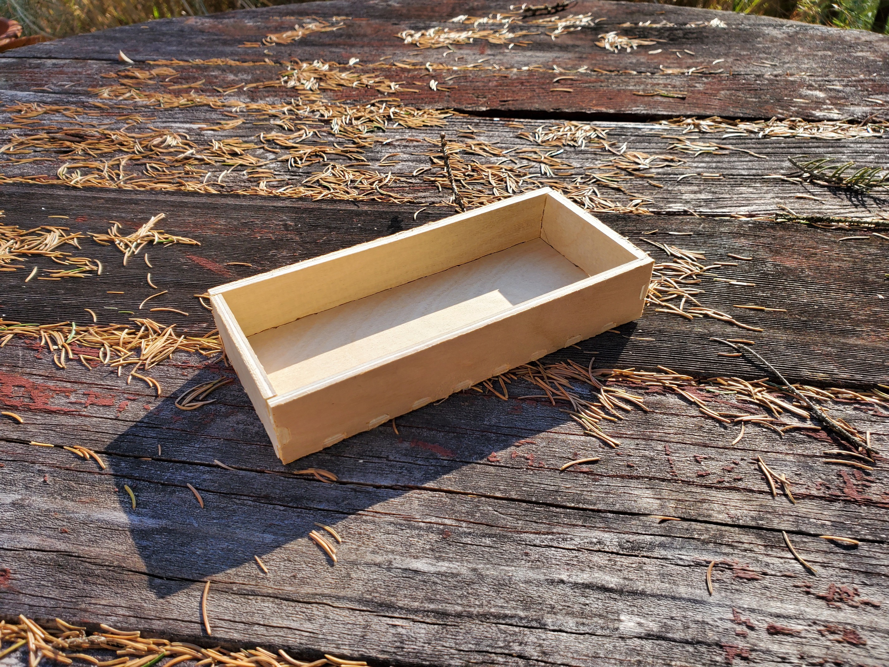
Conceptually it works:

4 Likes

I’m excited about making simple boxes. Laser folks have it easy with makercase and this looks like the equivalent with the CNC. Looking forward to you releasing this Will.

2 Likes

Thanks!

It’s been a hard row to hoe programmatically — I’m hoping to post a status update on the Kickstarter this evening.

1 Like

To do this for oneself, start with a suitable box generator: https://www.makercase.com/

which yields an SVG which one can open in Carbide Create:

box (3)

1 Like

The file opens in Carbide Create:

Select one part and assign a toolpath with the endmill which you wish to use:

(obviously spacing will need to be increased)

Previewing this shows:

which emphasizes that we need to relieve the fingers to allow things to fit together.

Drawing a circle of the radius/diameter of the tool which is used for the profile shows the geometry involved:

and drawing a square shows half the width which needs to be removed:

Drawing a rectangle twice the dimension of a finger:

shows the spacing needed for the circles:

While one could Boolean union these elements to create the shape, it is better to re-draw the desired shape using the curve tool:

This shape may then be duplicated, flipped, rotated, and otherwise placed over the fingers, and the parts arranged suitably, with a surrounding geometry added:

and with suitable toolpaths, one has a file which may be cut in one setup and two operations:

to make a box with parts as shown below:

1 Like

Sorry, I don’t see it. I mean, I see it, but I don’t SEE it. Looks like somewhere in there you changed bits or something. Best if I try to duplicate what you’ve done on a real board.

If anyone would like to try to cut this (it wants 5mm thick plywood) here is the file:

box_all_440.c2d (1.7 MB)

Cutting a hopefully final test project tomorrow.

I am just wondering why you chose to use a .25 dia bit to cut the box out When it could have been done with and .125 end mill and there would have been tighter corners.Also why does the simulation look like the wood has been rounded over.

Used a 1/4" because that’s the size downcut endmill Carbide 3D sells (used a #251) and to ensure that the radius of the cut would interfere with assembly and the wood looks as if it’s rounded over because I added a V carving operation to chamfer the edges of the fingers, which will hopefully allow things to be assembled anyway.

Finally had occasion to calibrate the machine (the second cut was intentionally done with a decalibrated machine) and it fits together quite easily — probably one could use a few fewer tabs in the .c2d file.

A further improvement might be to try cutting the areas for the finger joints only 1/2–2/3rds the thickness of the board deep, and shortening the fingerjoints by the inverse of that amount — that would hide the joinery, and slightly increase the gluing area.

litterally was just wondering if such a thing existed, holy smokes.

like, litterally just got up from itchen table looking at thee things i wanted to make boxes for without getting out my dado stack.

1 Like

but after looking at all the operations required after generating the SVG, it may be quicker to bust out the dado stack lol

what about using the boxmaker’s corner compensation option?

1 Like

Is that new? I haven’t looked at boxmaker in a long time, but I don’t remember that.
I use an extension in Inkscape for laser cut boxes, but I may take another look. For irregular stuff, I just use Fusion, but it’s not quick.