Design into 3D: Boxes: Magazine storage

Next up is more boxes, this time for magazine storage — for my part I just cut open Fed Ex boxes:

But they’re not always available in a suitable size for typical magazines.

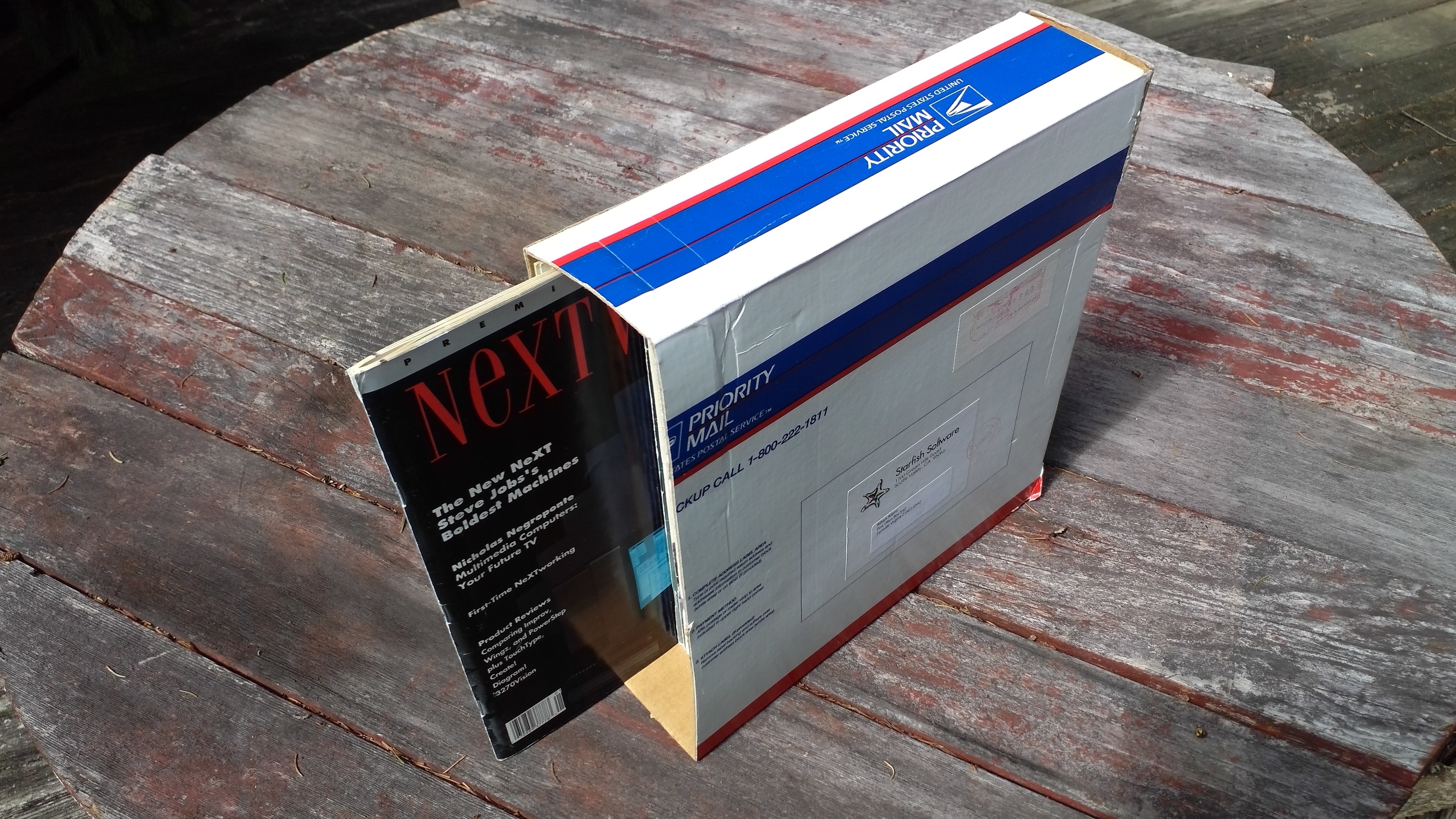
There are a number of commercial options:

So there is certainly precedent for wooden boxes — we’ll try for an inexpensive material, since this is going to be a fairly large project (sorry Nomad owners) — Luan Plywood is available at most home centers, usually as underlayment, a bit of care should allow one to pick out a sheet in good shape which can be cut up to fit on the bed:

https://www.homedepot.com/p/Underlayment-Common-5-0-mm-x-2-ft-x-4-ft-Actual-0-189-in-x-23-75-in-x-47-75-in-1507142/202089010

(it’s far more affordable if you can manage a 4x8 sheet).

First up, design.

5 Likes

First needed dimension is the thickness of the sheet — turns out the specification of 5mm is workable enough:

Thickness: 5mm

The magazines themselves are 10" x 12", and the stack is roughly 3.25" thick, so for this sort of box, we set it by the interior dimensions:

Width: 85mm (all dimensions are rounded up)
Depth: 260mm
Height: 310mm

We go to https://www.blockscad3d.com/editor/ and create variables for those dimensions:

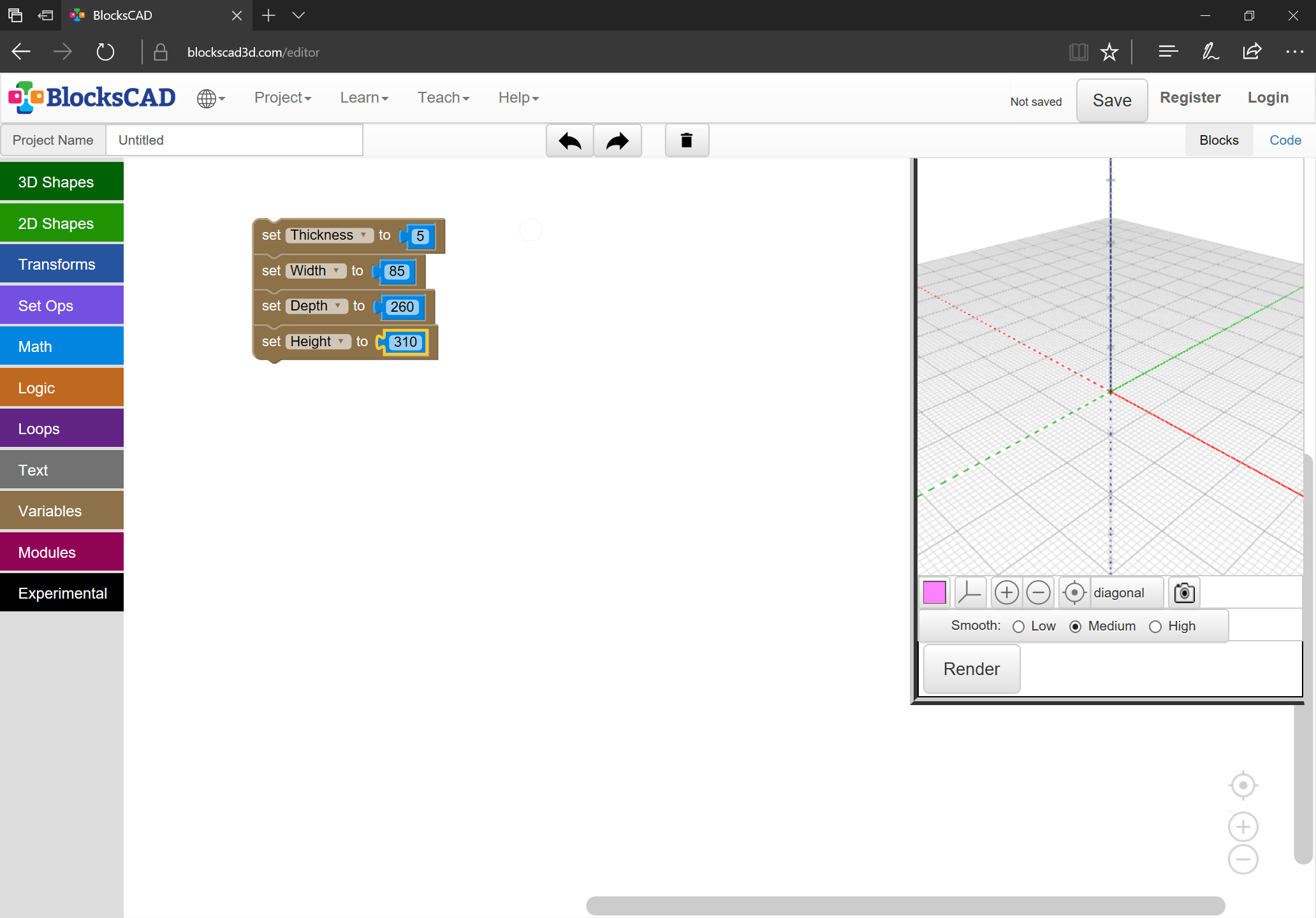
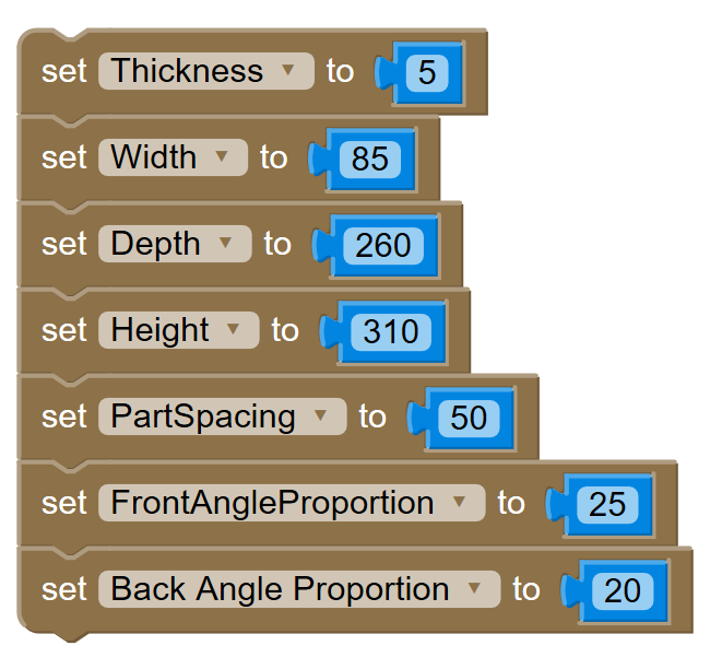
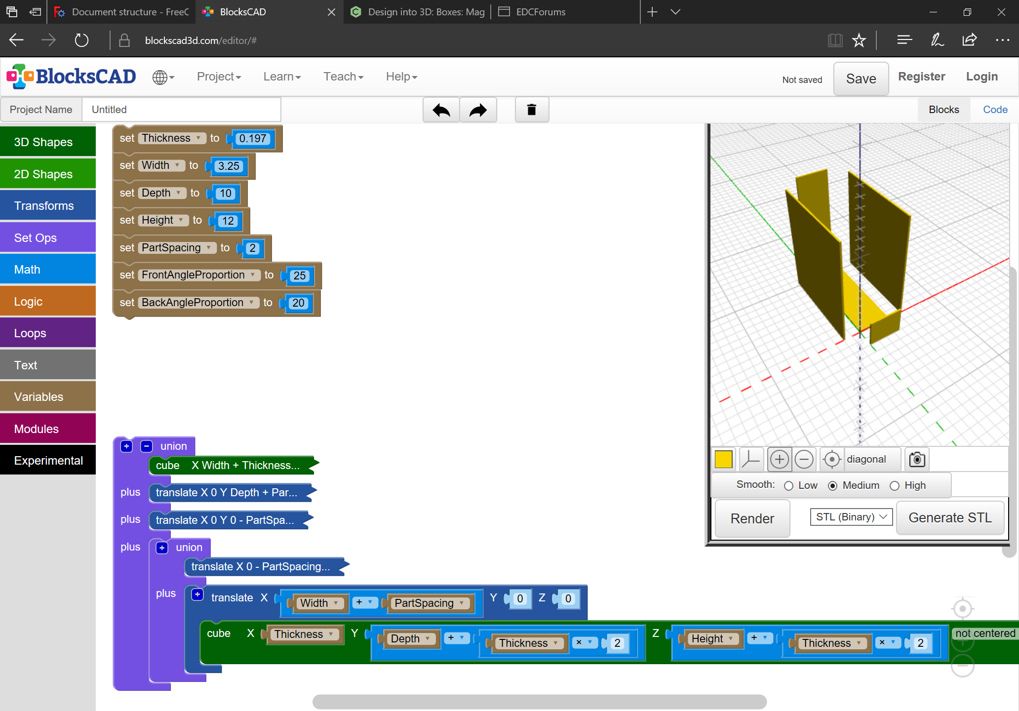
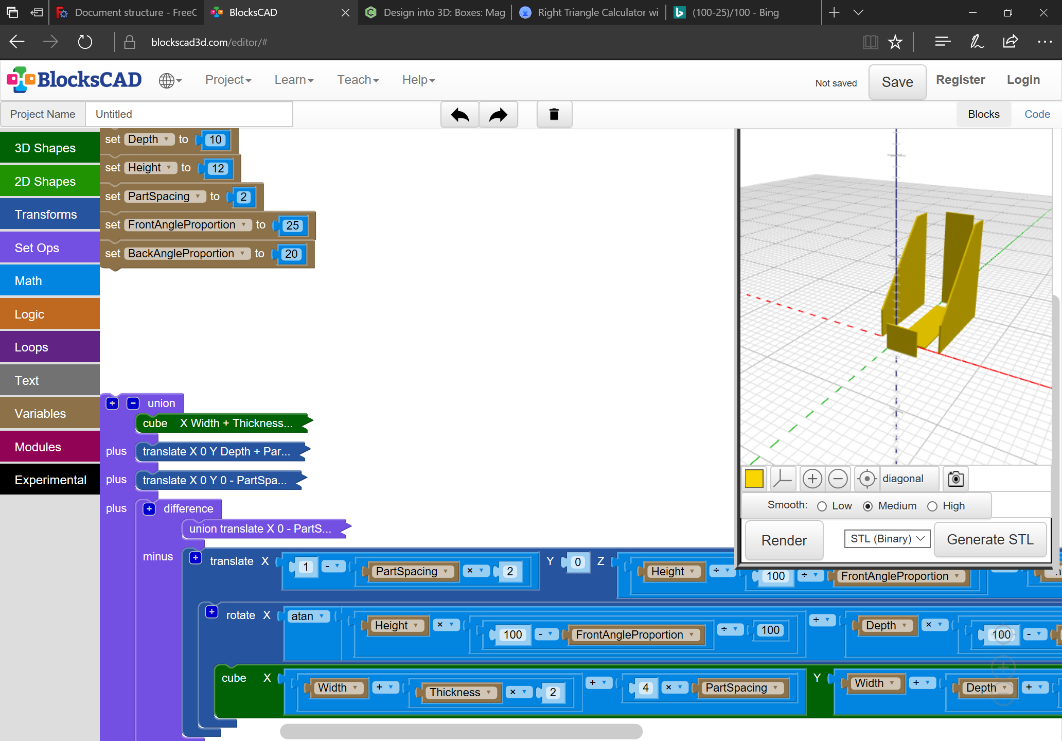
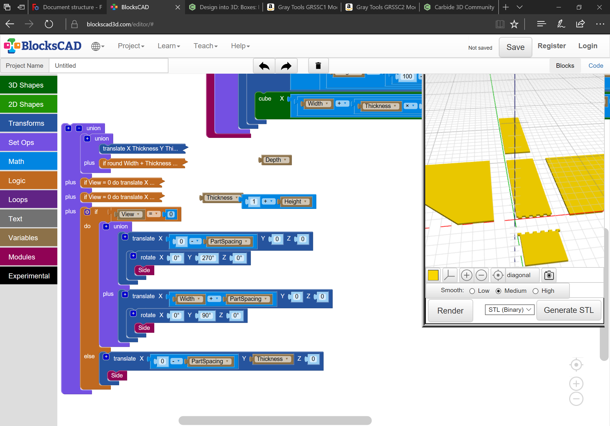
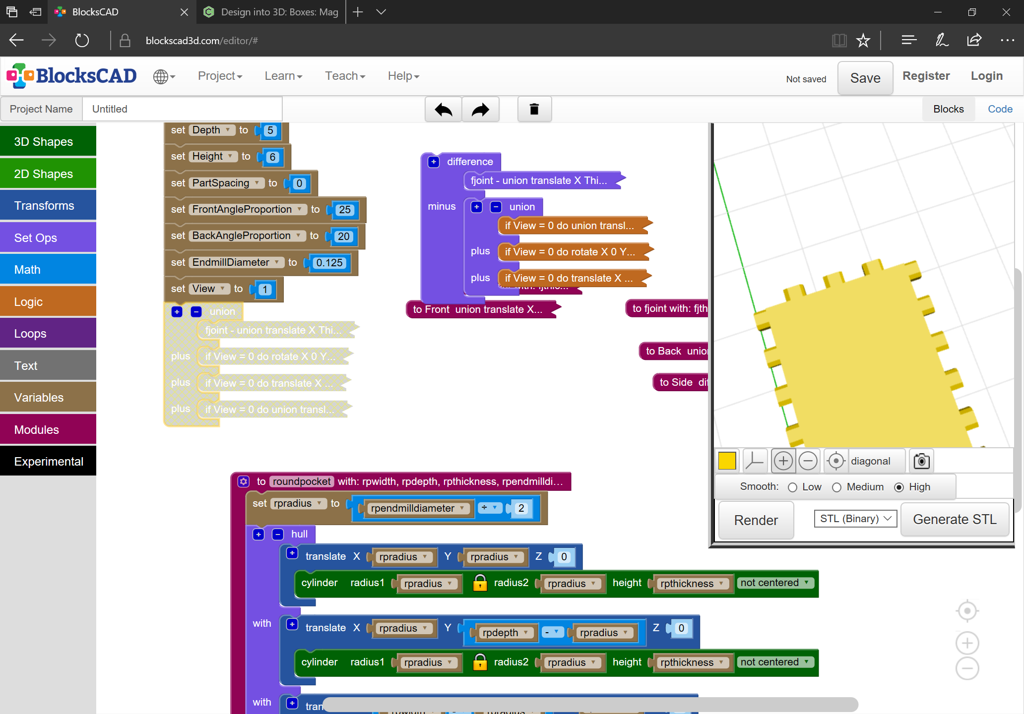
We need one additional variable — Partspacing, and if we are going to have an angle to this, we should also allow specifying that slope — rather than specifying the angle directly, we can use the proportion / percentage at which the angle will begin along the front height, and end along the back top:

1 Like

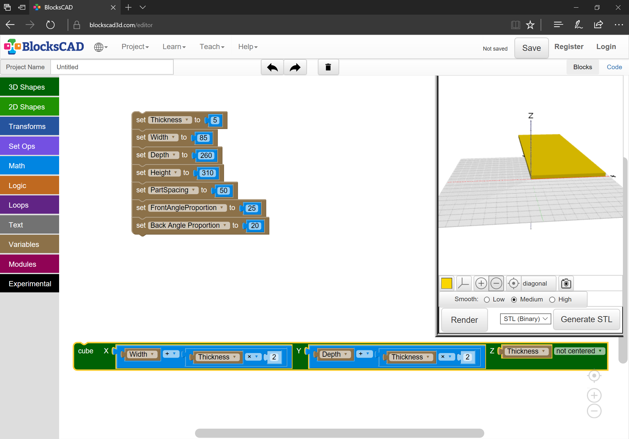
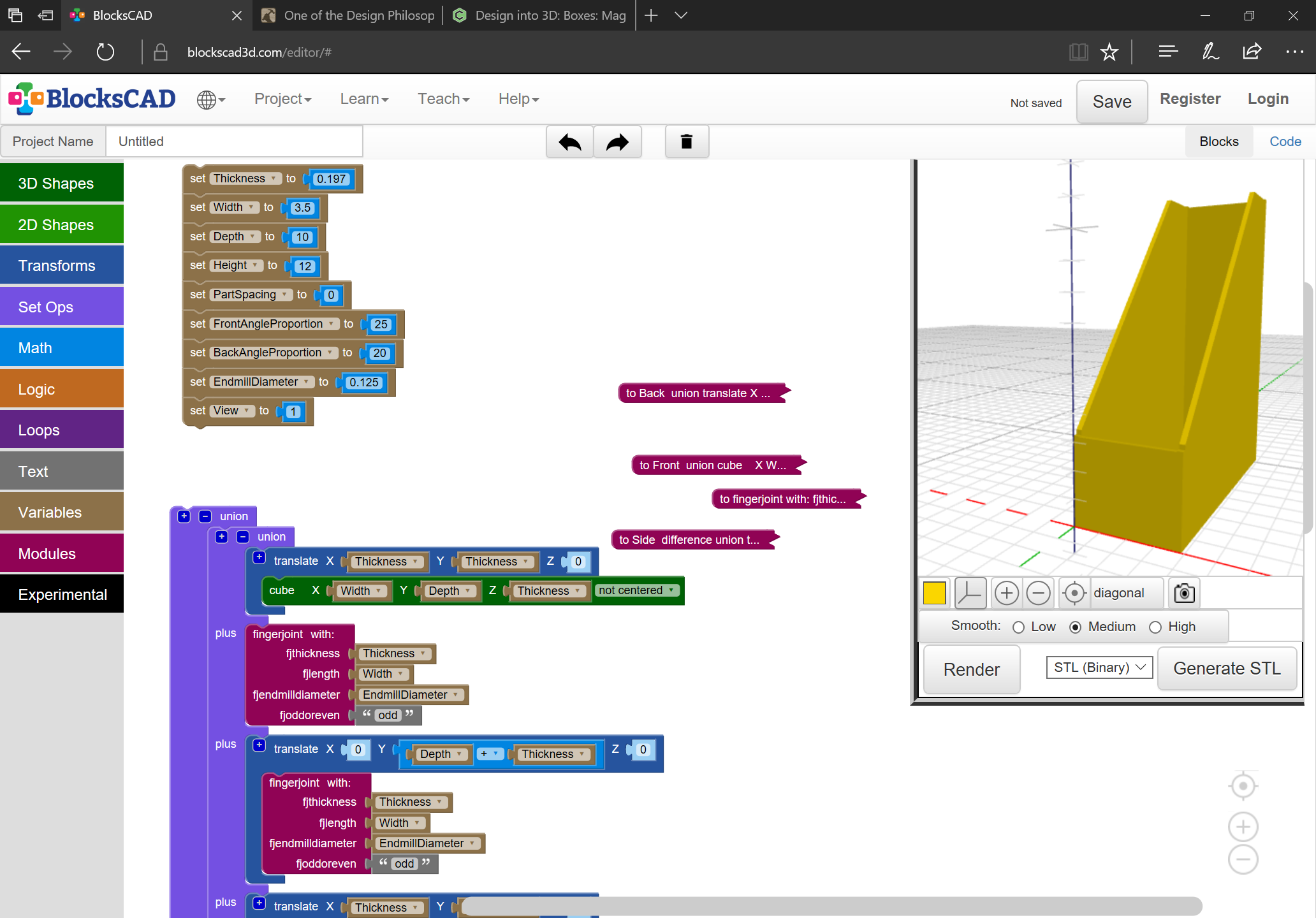
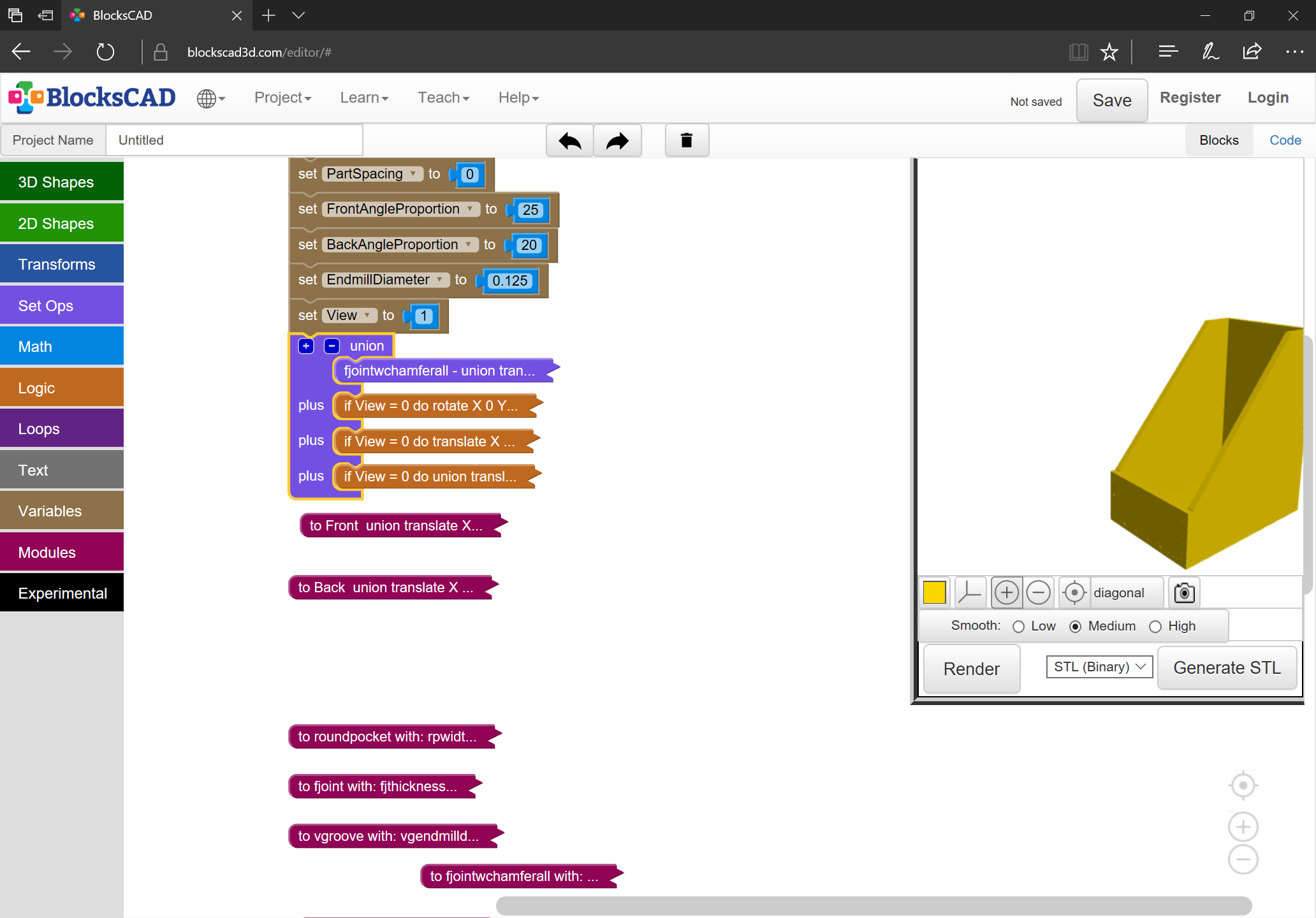
But, it’s a little large for the working area, so maybe we’ll use Imperial after all (that’s the nice thing about variables, they can easily be changed out):

1 Like

Drawing up the basics of the parts is pretty straight-forward:

The tricky part is doing the trigonometry to get the angle right.

1 Like

The needed angle of rotation is:

arctan ( (height-proportion) / (depth-proportion) )

Next up is working out the joinery — finger joints should work well, but will need two additional variables:

  • endmill diameter
  • number of joints

Or, maybe just endmill diameter, and # of joints will be auto-calculated…

1 Like

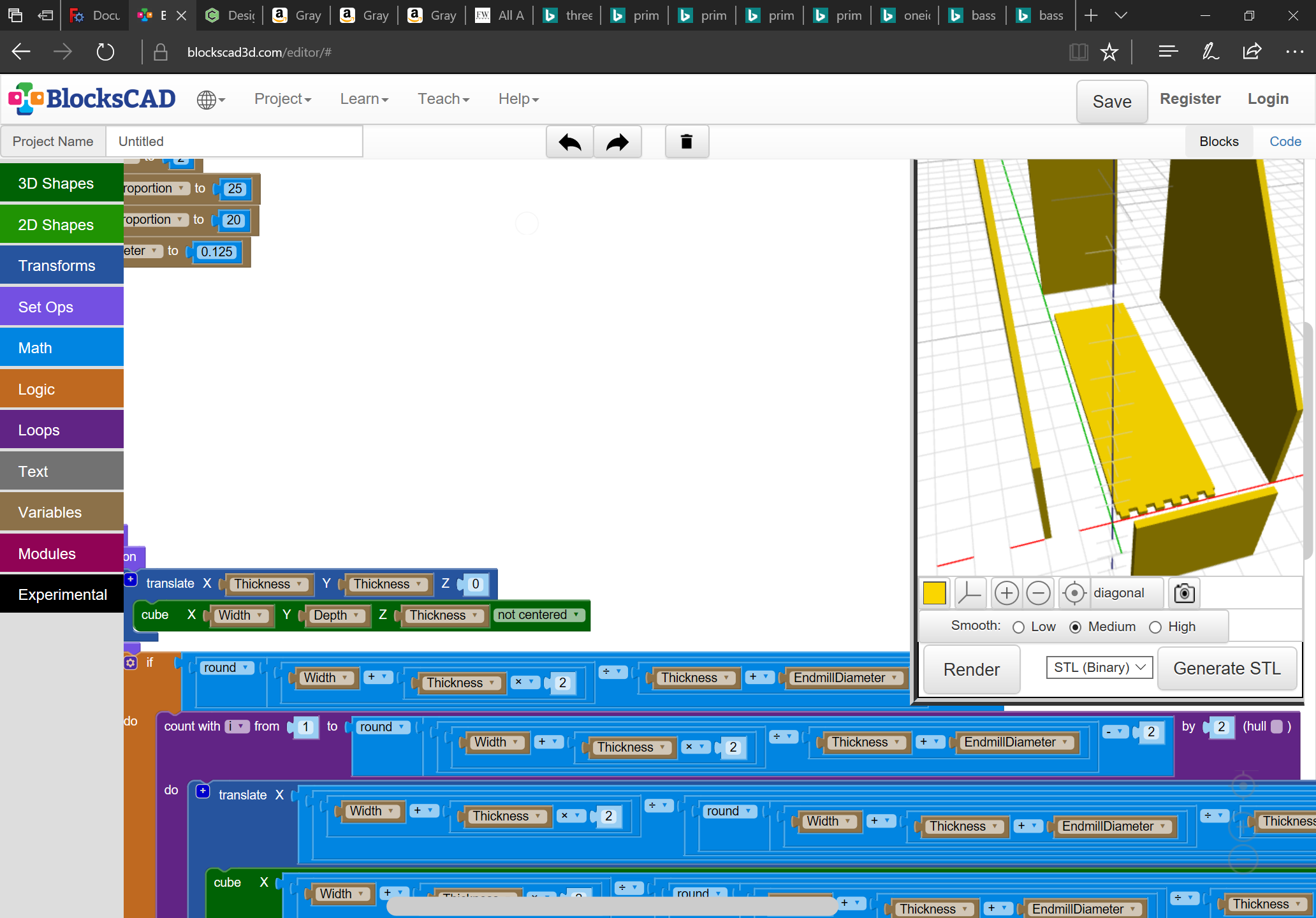
For a given joint edge we want an even number of pins on one side, and an odd number on the other.

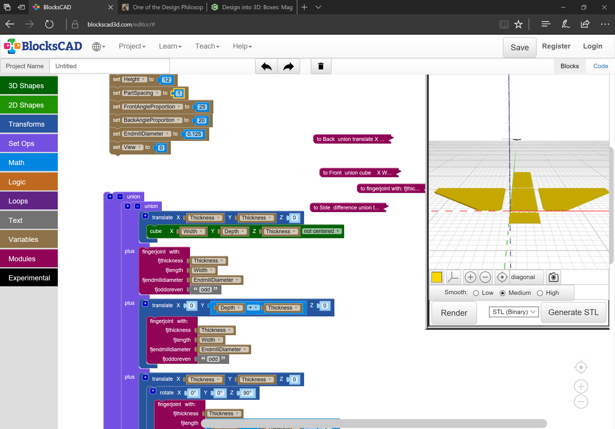
We need to ensure that the pins are proportional to the material thickness, and will admit the endmill — easiest way to do that is to add:

pinwidth == Thickness + EndmillDiameter + X

where X == the additional length needed to make things come out evenly along the width (note that if the box is not square / proportional width of pins and their number will differ along each axis).

Note that the traditional suggestion is pin width is half stock thickness: https://www.finewoodworking.com/2005/09/12/all-about-box-joints

The first number we need is the number of pins on a given edge.

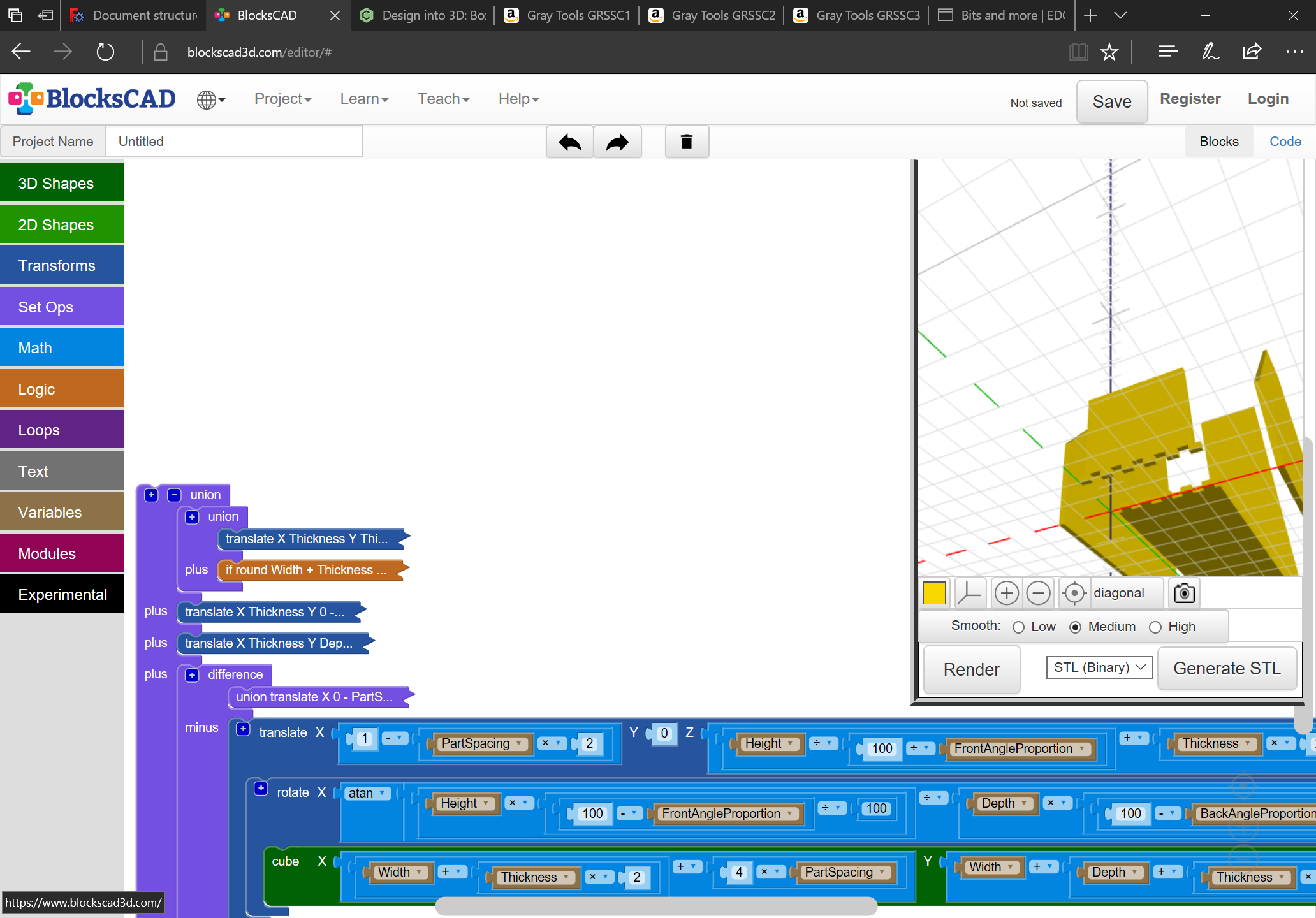
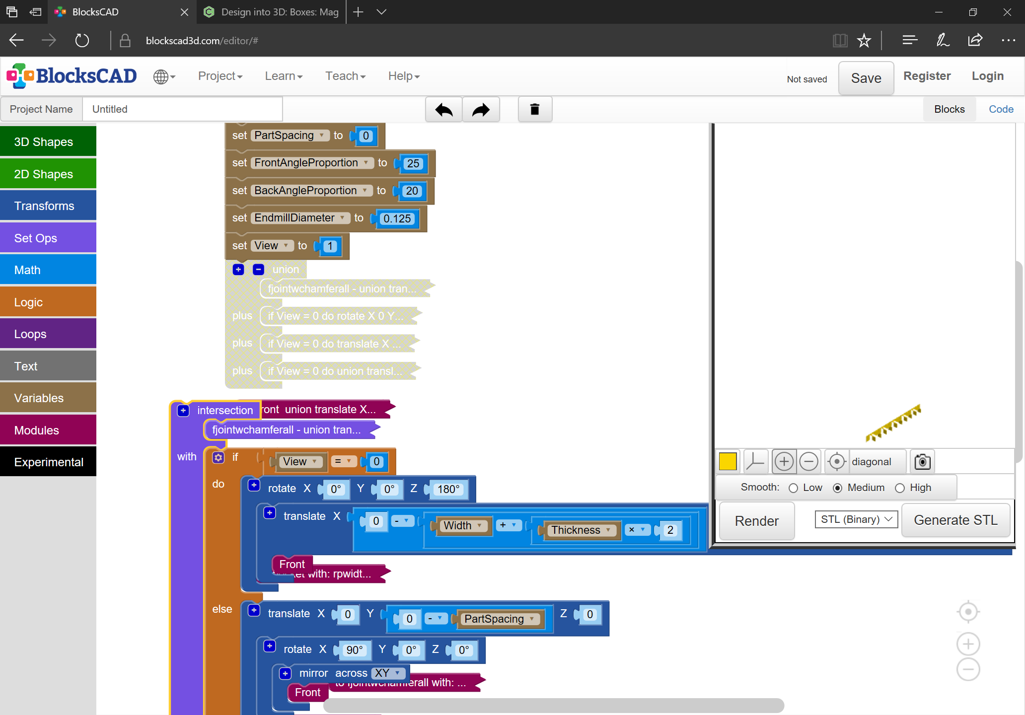
A bit of judicious math and calculations (and changing the bottom board to not include the dimensions of the fingers so that they can instead be added) results in:

Next the corollary to that needs to be coded up:

and the whole converted into a module which is generalized to:

  • allow specification of the desired axis (along X, Y, or Z)
  • input board thickness, endmill diameter, and overall box dimension as parameters
  • specify whether an even or odd number of pins is required
1 Like

In retrospect, laying out the parts flat and having an option to rotate them into the exploded (or assembled) view makes a lot more sense:

(some further adjustment to make the normal position flat is still necessary)

1 Like

And we now have joints on all edges which need them:

and they fit together perfectly:

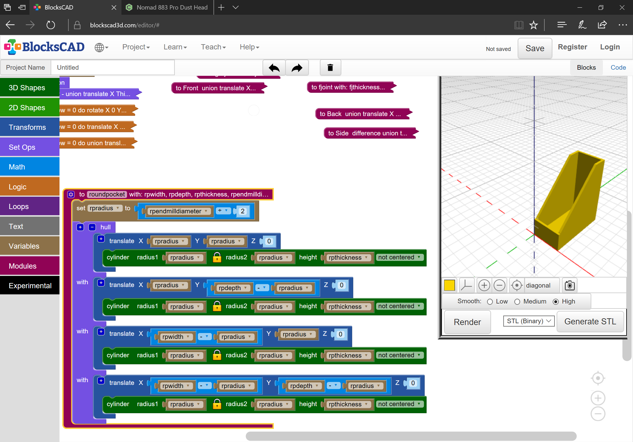
if only we could cut such angles conveniently — unfortunately, making these cuts as shown would require one setup for each set of joints, and a careful measuring of placement — the bottom alone would require 4 setups. Not really practicable.

2 Likes

Adding a rounded pocket macro and adjusting to use that eventually has us back to where we were:

but with the ability to subtract parts and see the shapes we need to make to allow things to fit:

1 Like

Adjusting the logic so that the exterior edges aren’t chamfered gets us to:

which has minimal interference:

and a good appearance:

Next up is working out how to create a cut file.

2 Likes

Hey Will, do you keep these tutorials somewhere like the Wiki with a short description? I guess they are here in the tutorial section but it may be hard to find what you are looking for especially if it was done a while ago. We may have no use or time for this at this time bnut later, we may want to get back to it or we may have missed one of your posts on something of interest. I have no idea what you covered last year for example and maybe that info would be useful in a project.

If you have a repository of tutorials, can I suggest that when you post these tutorials, you put a reference in the first post of the thread as to where these tutorials are kept.

I’ve tried to collect them on the wiki, depending on subject:

Not sure of anything else I’ve done which warrants collecting.

3 Likes

Maybe as a suggestion, you should insert a note at the bottom of your first posts, something like:

You will find tutorials and creative ideas like this for your Shapeoko and Nomad please consult the Wiki

It is a reminder that there may be something of interest to consult.

1 Like

Unfortunately, we don’t have signature blocks here — I’ll have to give that some thought.

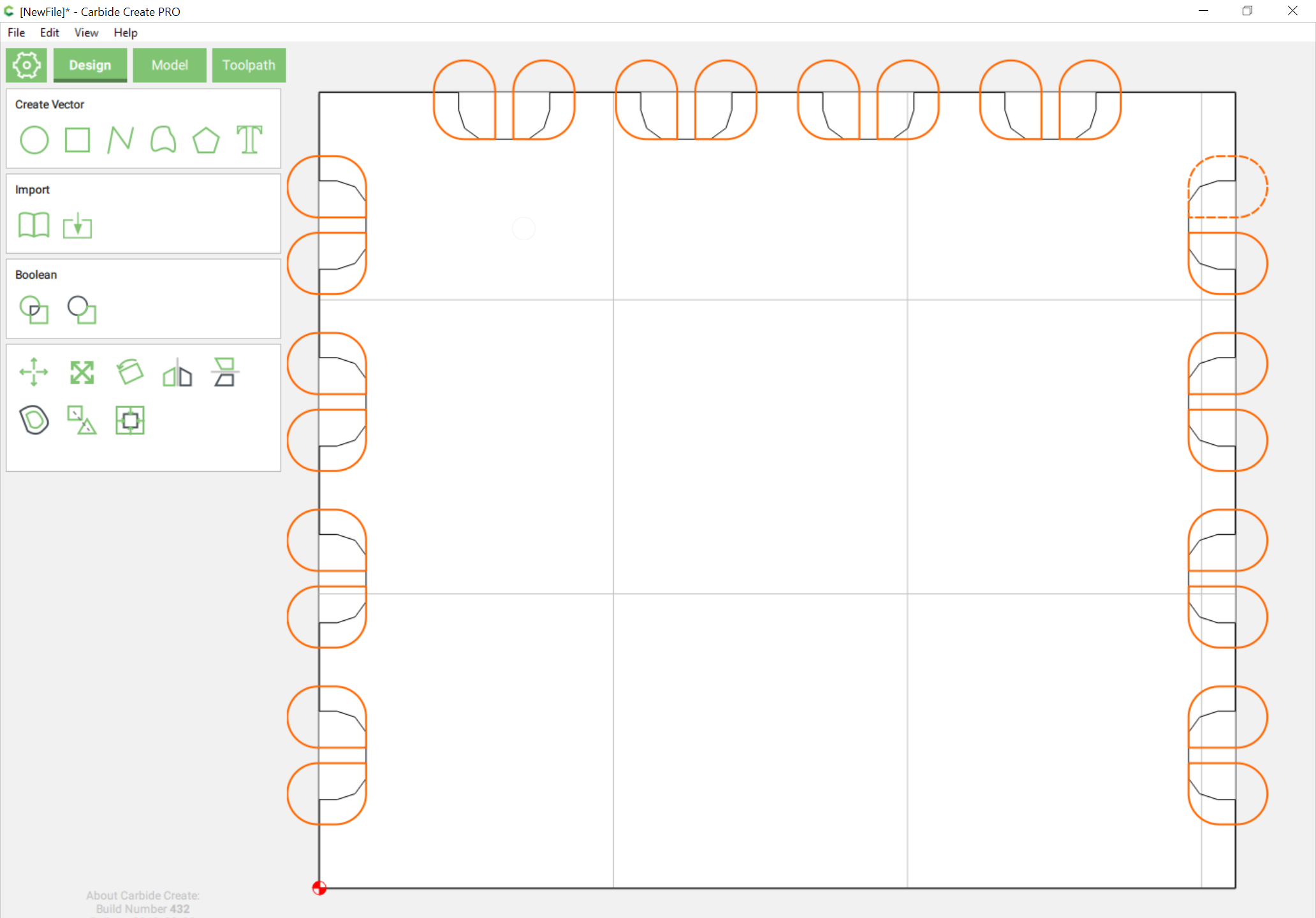
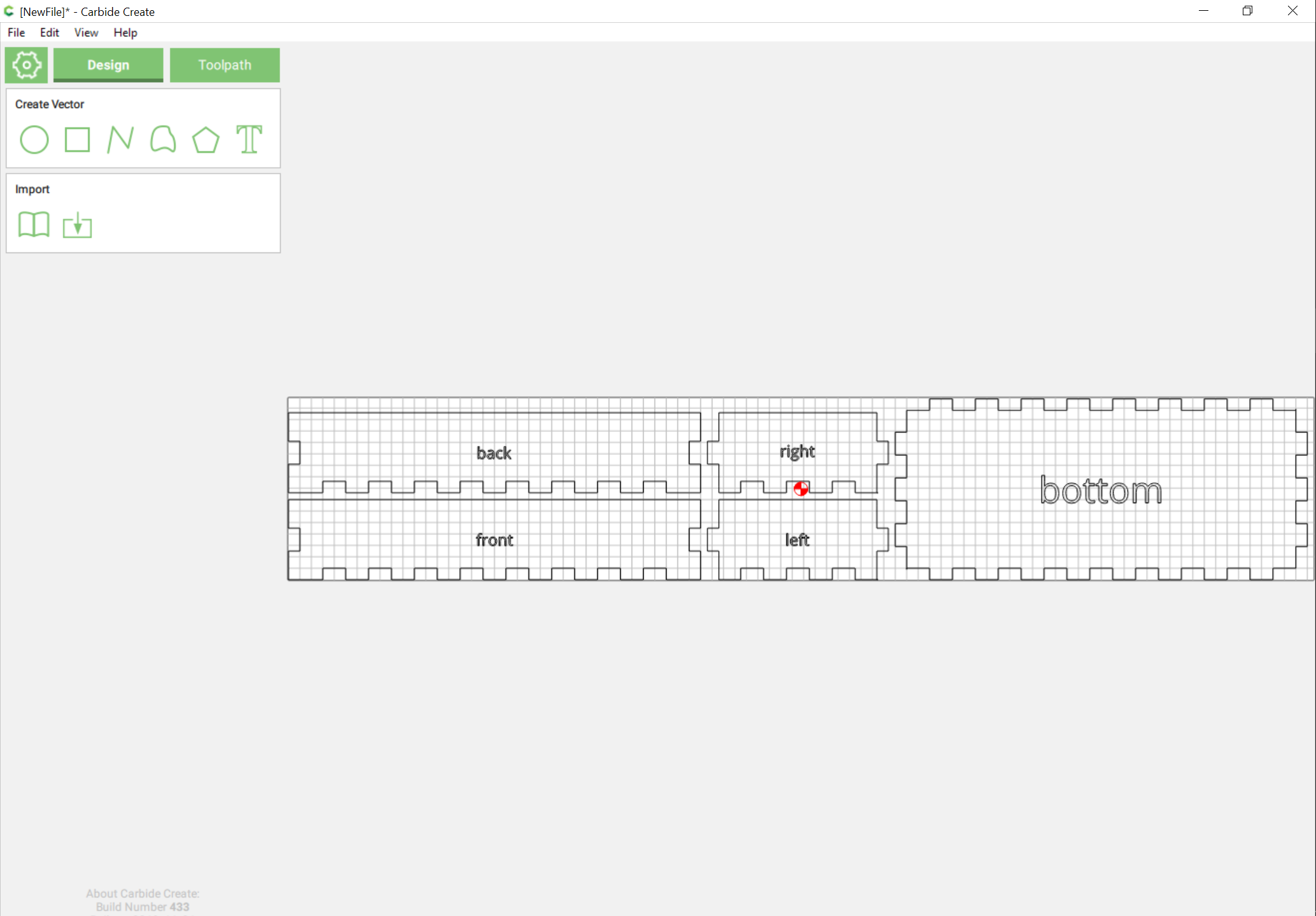
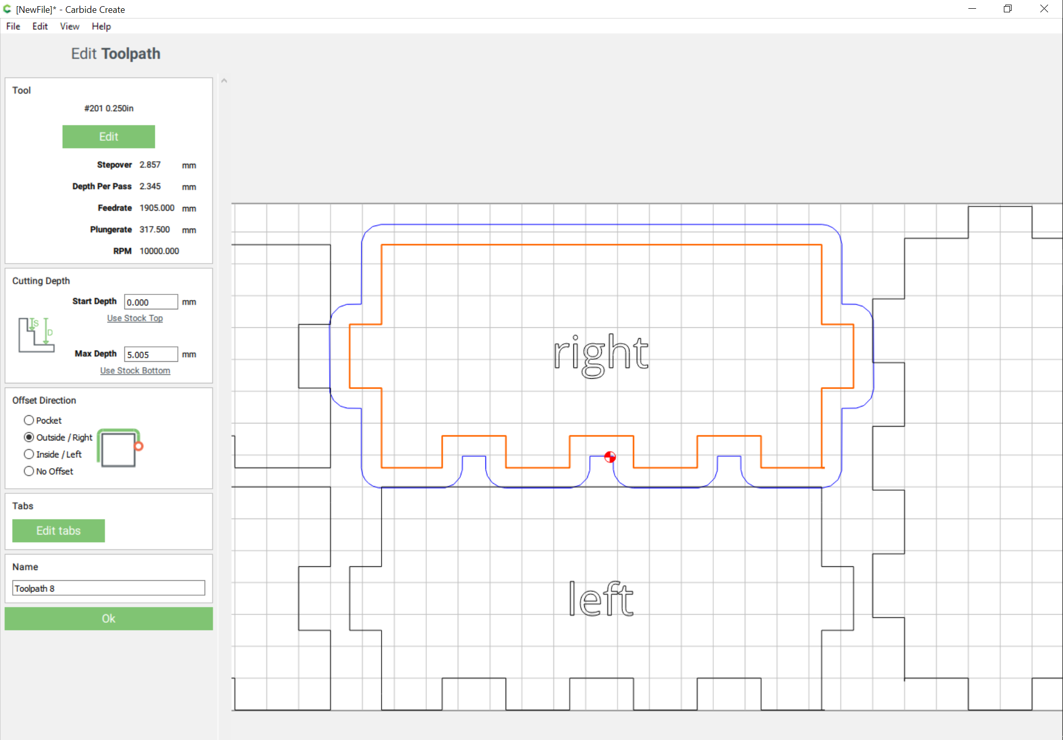
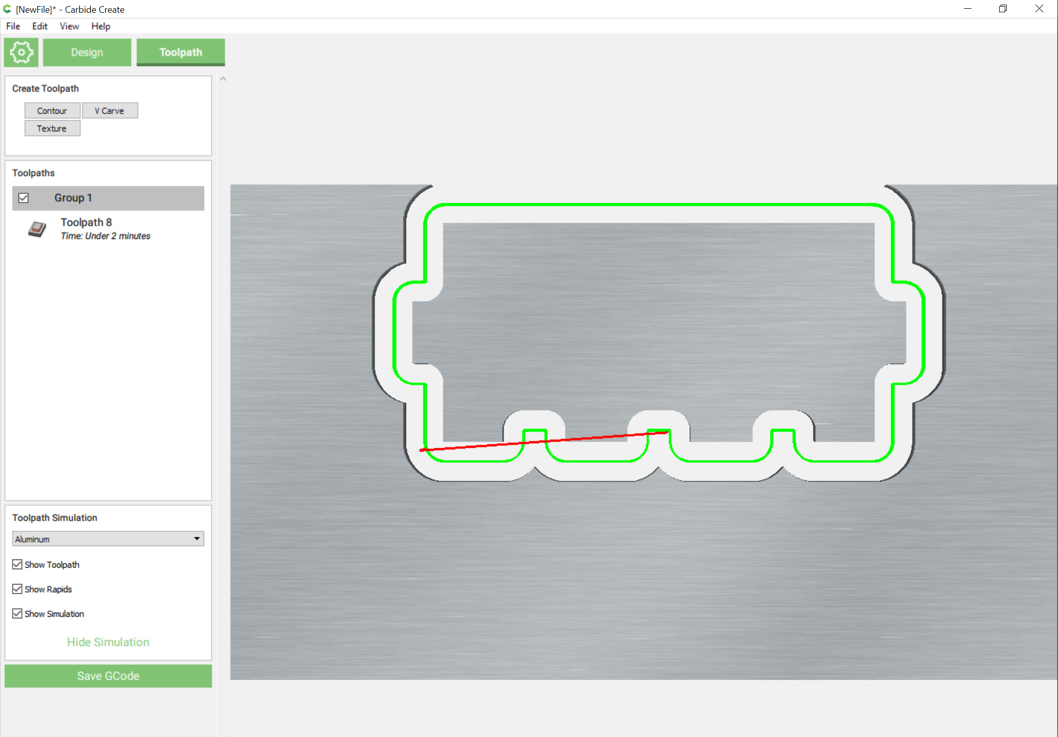
I’ve cleaned up the .scad file a bit, and posted it to: https://github.com/WillAdams/Design_Into_3D/tree/master/box/fingerjoint/magazine and made a .dxf — next up is puzzling out doing the joinery in Carbide Create, then I’ll have to work out a technique for automating making vector files using METAPOST or some other tool.

DXF import is a bit rough, but this seems to be the shape needed to chamfer the fingers with a V carving:

and the 3D preview seems good:

Next up is making a file for a prototype, then I’ll have to revisit the automated drawing.

1 Like

Conceptually it works:

4 Likes

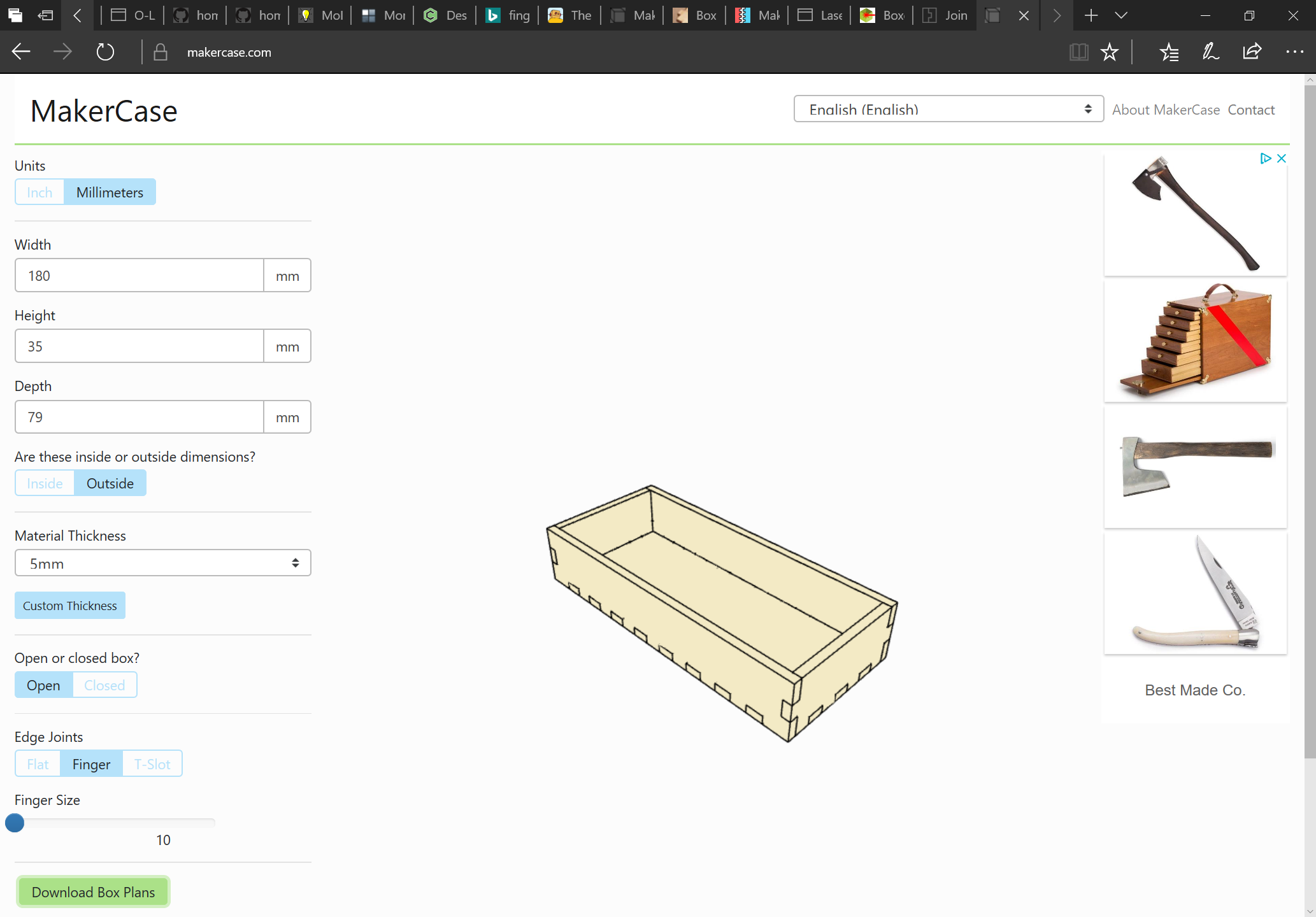
I’m excited about making simple boxes. Laser folks have it easy with makercase and this looks like the equivalent with the CNC. Looking forward to you releasing this Will.

2 Likes

Thanks!

It’s been a hard row to hoe programmatically — I’m hoping to post a status update on the Kickstarter this evening.

1 Like

To do this for oneself, start with a suitable box generator: https://www.makercase.com/

which yields an SVG which one can open in Carbide Create:

box (3)

1 Like

The file opens in Carbide Create:

Select one part and assign a toolpath with the endmill which you wish to use:

(obviously spacing will need to be increased)

Previewing this shows:

which emphasizes that we need to relieve the fingers to allow things to fit together.