Screen mirror for laptop/tablet webcam

Some folks have found it useful to reflect the webcam on a tablet/laptop down towards the keyboard, positioning a whiteboard or sketchbook or other flat object to project. Here’s a quick project for one:

https://www.blockscad3d.com/community/projects/1154421

It simply needs a small mirror, two SHCSs, and a matching coupler. It’s designed to be cut on a machine, but may need either a bit of cleanup w/ a file or chisel, or cutting in multiple orientations using suitable fixtures:

1 Like

In order to make one, one need to know the thickness of the laptop lid/tablet — while tablets often include this in their specifications, laptops rarely have a separate thickness for the lid.

Tool to allow measuring:

thickness_gauge_4–10mm.c2d (1.5 MB)

1 Like

A first cut went well:

1 Like

Nice,

Are you going to put some white paint / chalk in those engraved calibration marks?

I was thinking silver/aluminum (I have some metal paint somewhere).

1 Like

Exporting to OpenSCAD and adjusting the code a bit we arrive at:

Projecting to make a file which can serve as a beginning for cutting:

Attached.

Screen Mirror.zip (921 Bytes)

Next up is importing into Carbide Create and working out how to cut this out.

Decided on a slight adjustment to the design (will go back and modify the 3D modeling code later):

The basics of cutting things out are pretty straight-forward:

(need a bit of an adjustment there, hang on):

The spine of the mirror holder will need to be rounded at least enough to allow a reasonable positioning of the mirror.

There are several ways to accomplish such rounding:

  • use a cove radius endmill — unfortunately, Carbide Create doesn’t support such endmill geometry, so no 3D visualization, and not sure if a 4.5mm radius endmill is available. See: Design into 3D: Boxes: Magazine storage for some further information on this
  • Export the STL from OpenSCAD and cut using a 3D CAM program, or by using a utility such as: Cutting STL models with Carbide Create Pro (nearly-2021 edition)
  • manually program the G-code to round things off
  • draw a succession of geometry and suitable toolpaths to cut this — this is the technique which will be used here

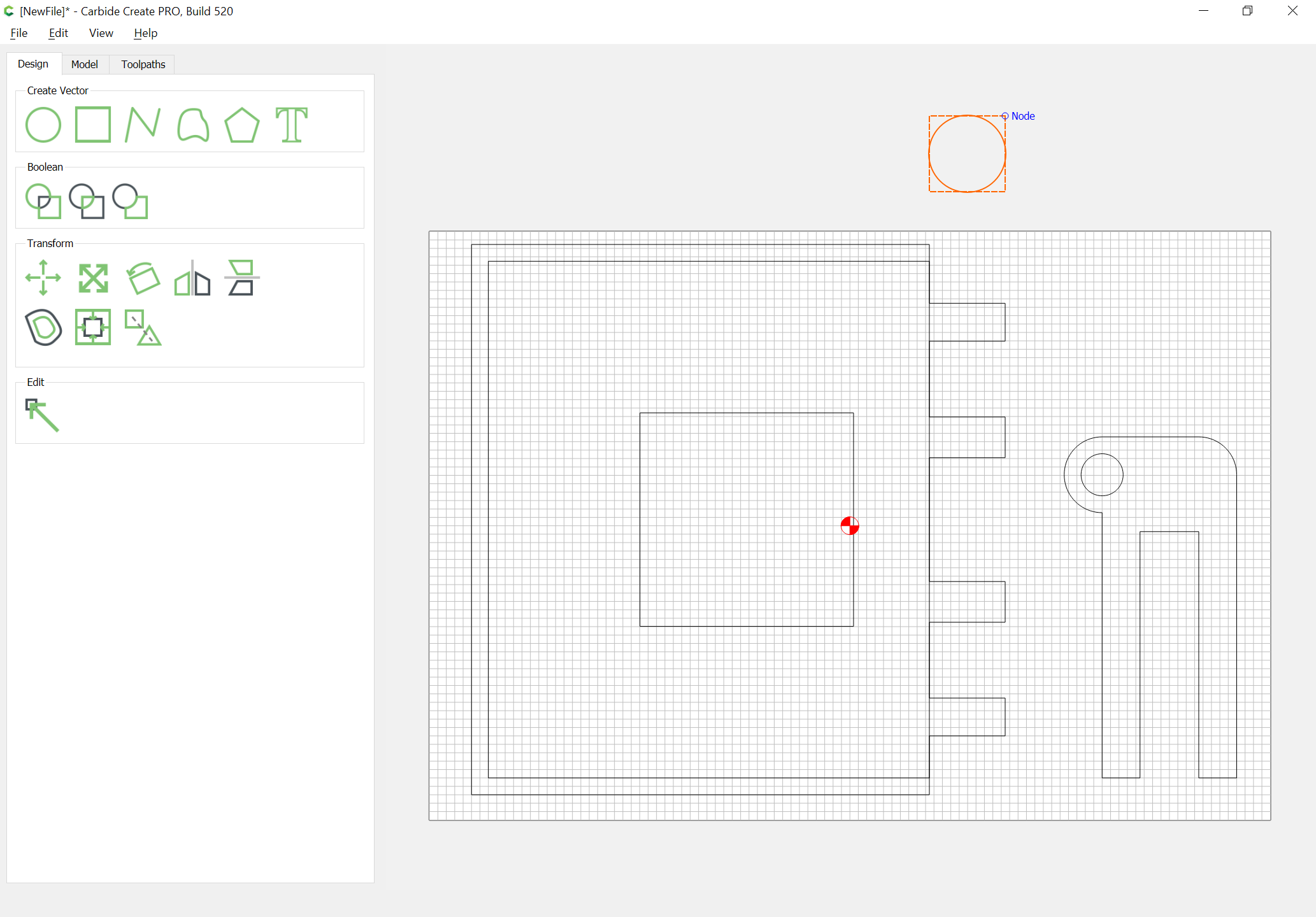
Visualizing this will be easier if we rotate things to line up and draw in the geometry in register:

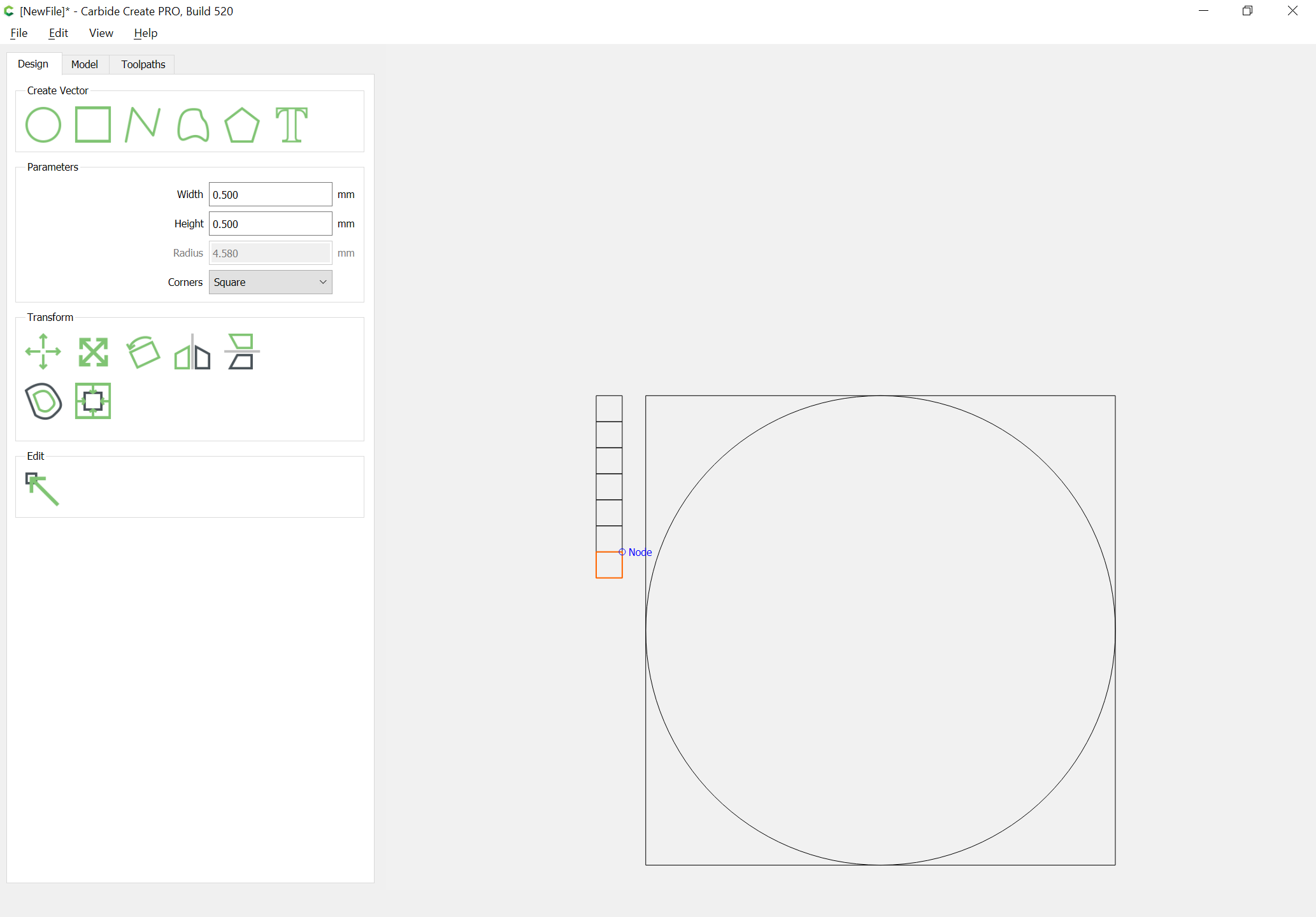
The depth per pass is 0.508 mm for a #111 ball-nosed endmill — rounding down we want a stack of 0.5mm squares to indicate the depth we will be cutting to:

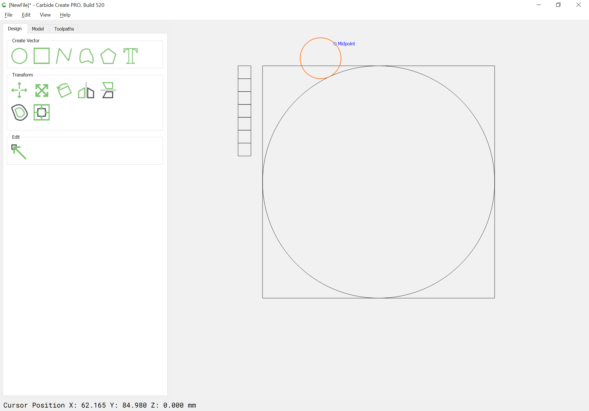
Drawing in a 1.5875mm diameter circle we align it with the bottom of the top rectangle:

and then nudge it over until it just touches the circle which represents the desired rounding:

Draw a line which is radius longer than is needed at each end:

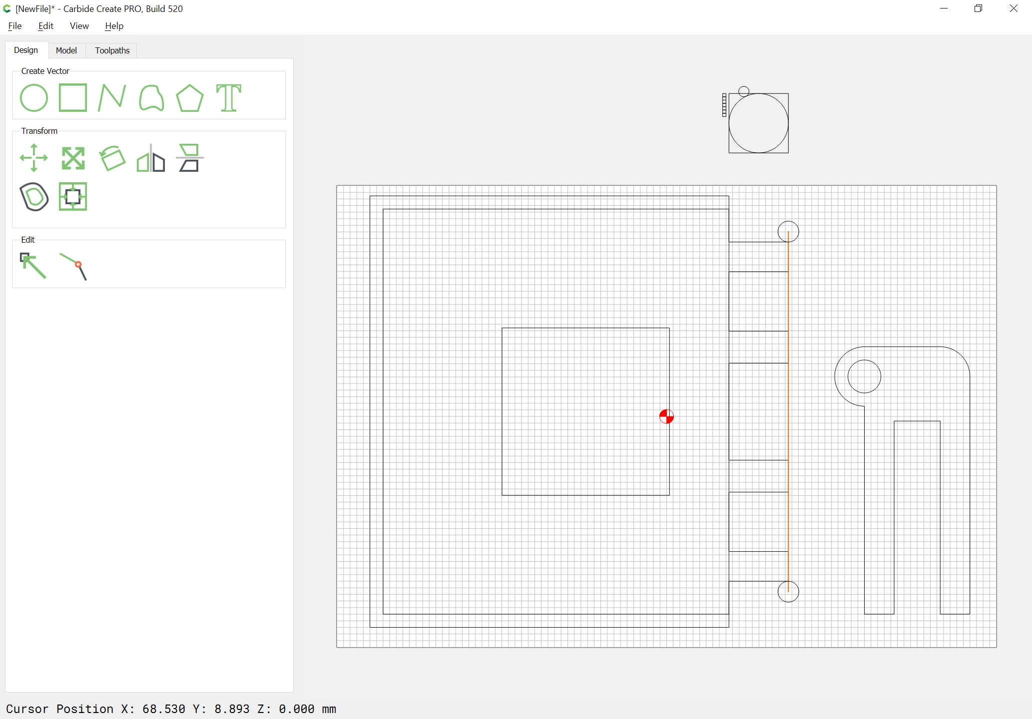
align it with the center of the circle:

and assign it a Contour No offset toolpath to a depth of 0.5mm:

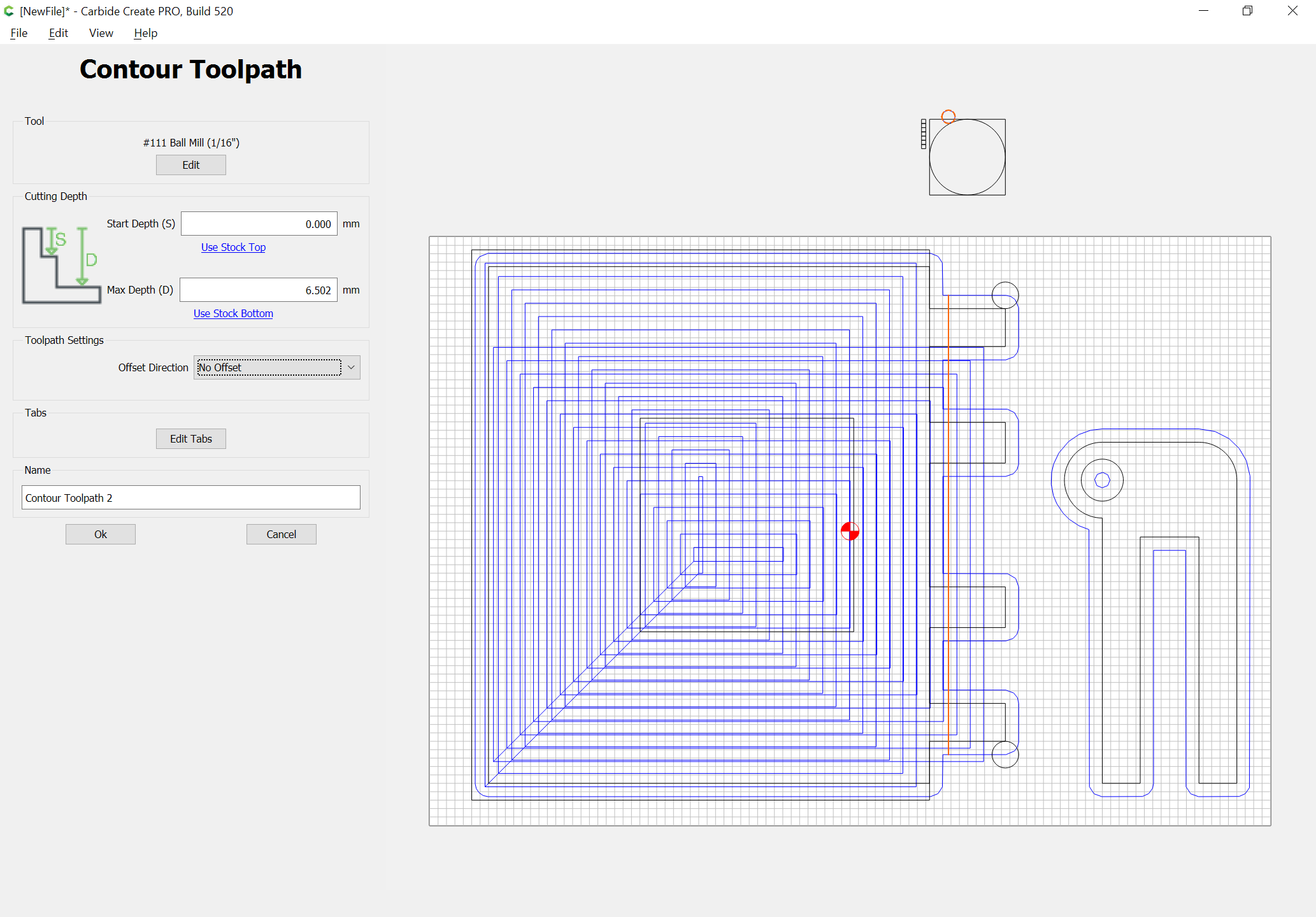
Repeat for each depth square.

Eventually one arrives at:

If one is more patient, and willing to take shallower passes, the appearance and fidelity could of course be improved.

With a bit more patience one can get a fairly smooth appearance:

Attached.

Screen Mirror.c2d (240.0 KB)

1 Like

Didn’t have SHCSs long enough to reach the coupler, but the holes I drilled were tight enough to hold anyway:

Mirror needs to be larger than 1"x1", so will have to see if some size is available in-between that and 3"x3" (the next size up at the local craft store).

1 Like

This topic was automatically closed after 30 days. New replies are no longer allowed.