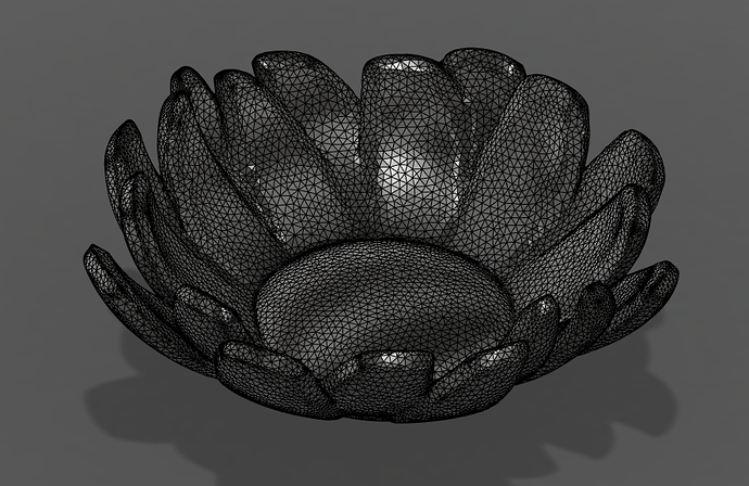
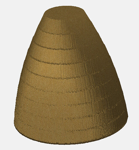
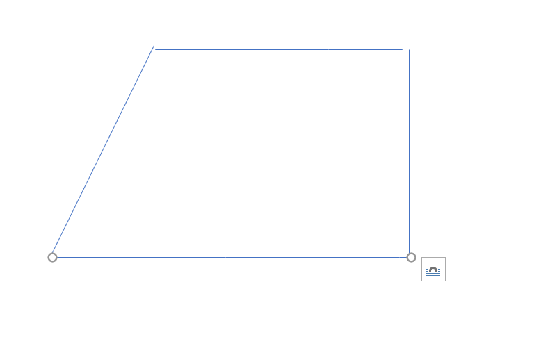
Please post, or e-mail support@carbide3d.com an STL which will not import into the Mac version of Carbide Create
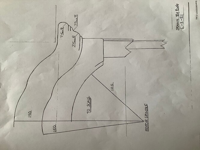
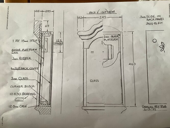
Rob,apart from the bowl and dish type products I would very much like to have an easy way to make these clock crowns.Will helped me a lot to get one done but have various other designs to do.Here is the example of what I was mentioning.
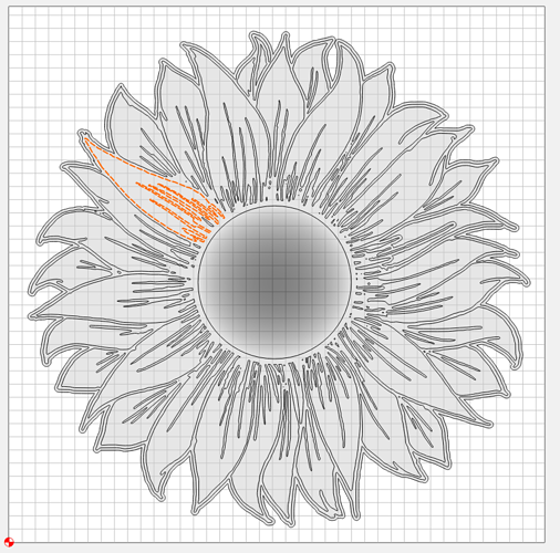
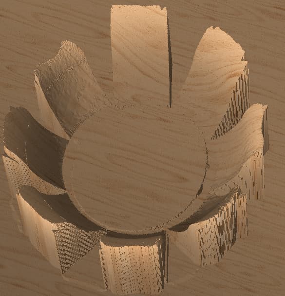
This could be a pretty one off type problem, so not sure the effort is worth the potential end result, but I’d like a way to add I guess weight or more control over points in round or some sort of gradient raise? Like this example here:
If I wanted the petal to start inside the petal and slope up, I currently can’t think of a way to do that. It’d also be kind of cool to be able to define individual heights to the different petals so that some reach up taller than others.
Again, not sure how usable it would be across the community, so not sure it’d be worth the dev effort.
Here’s the file. I can add more context if needed.
sunflower test.c2d (1.8 MB)
I second this! I make furniture, and being able to import a moulding profile in the Z axis (like this: Cornices Orac decor DWG, free CAD Blocks download) and have it follow a spline on the X/Y axis would let us do things that aren’t easily possible with any other woodworking tool.
I bought a Shapeoko to help me make intricately carved panels for furniture. My previous experiences are oriented around 3D printing, so I’m very familiar with Thingiverse and other commercial model sites, and I frequently use STL files.
When constructing a panel, STL files are like 3D stamps to me. I want to drop them into a model as design elements, assembling a collage of them towards the final design. I want to be able to adjust their elevation and rotation, and stretch, shrink or grid deform them to match a dimension or constraint. And I’d like to be able to crop or slice off portions of an STL file to extract the element I want from a more complex design before using it as one of these stamps.
I do many of these operations by converting the STL to a heightmap and manipulating it in Photoshop. It’d be great to be able to do this natively in CC Pro.
If you draw up such in profile in Carbide Create, you can then assign suitable tools to create the profile using a succession of no-offset contour toolpaths — see:
If you’d like to pick one profile and would list the tools which Carbide 3D makes which are suited to cutting it, I’d gladly work up a step-by-step for that.
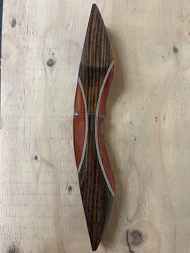
That is some fine bows You are making, I had a look on the website.
Thank you! Now if I can figure out how to program them into my cnc I won’t have to build everything by hand. Lol
Just playing around a bit.
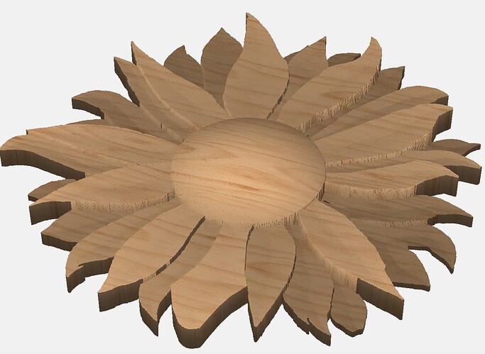
This is the sunflower from above.
Still needs v carve lines
There is a small arc on leaves from outside to inside. Plus leaves are cuffed
Used CC Pro
I was looking to do something more like this (from the 2.5D perspective):
Which really may be more outside of what Create pro is looking to do, but I figured I’d throw it in the ring for consideration.
I see a lot of relief images that for example say welcome to and then have a blank spot. It would be nice to be able to insert text or an image of what I’d like into a certain spot into the relief png or stl file
That is pretty simply done now — just draw in what you want in the blank area, or draw geometry which describes the blank area and import the design you want into that geometry — it will come in at the center.
Thanks, Will. That looks like it’ll take a lot of patience for a complex profile. ![]() This was more of a a wishlist post for CC Pro for a moulding toolpath, like this: Moulding Toolpath - VCarve Pro V9.0 User Manual
This was more of a a wishlist post for CC Pro for a moulding toolpath, like this: Moulding Toolpath - VCarve Pro V9.0 User Manual
Josh this is a quick cut on to flowerish pot above.
Inside/top cut for 8 peddles. Needs outside/bottom cut. Like inside and outside of a bowl.
I would make two bowls, one a little larger then the first. then stack them. Would look nice.
Safety first, make some saw dust.
For that, you will need either a 3D model of it, or a depth map version.
Thanks Will, maybe I am missing the intent of Rob’s request. If we find or have images like mine, I’d like to have a way in the software to take a grayscale image and build that depth map. Otherwise I am aware I would need a 3D model or depth map of it.
I just booked a job for next year…will be making these tables under glass. I plan to cut each layer upside down, with separate contours for each layer, and use modeling to get smooth outer profile. I’m guessing there’ll be a little math to calculate the position of each layer to make sure it lines up within sanding tolerances of the next layer.
I don’t know if there are any special functions needed…just how to know the size differential from the top to the bottom of the outer angles so that each layer can line up correctly. I’ll also need to be able to model a curved vector in which only one side is angled up…that might be a little tricky.
- Gary
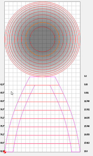
Playing around with 738 and how you would do that currently.
Came up with this by modeling it in NX and measuring the angles & diameters
But the best I could get the model was to use 2" tall limited angled components.
Tried with round, but it looked a lot worse.
