It’s been a while since I did the previous version of this tutorial (From STL file to Carbide Create (PRO) [screenshots included]) and the various pieces of software have changed a little so I figured it’s time to do a refresher.
Some of the screenshots on the forum look a little tiny, but just click on them and they should become very readable

Step 1) Finding a good STL file
Not all STL files will cut equally well on a CNC; a 3 axis CNC only cuts from the top so any kind of “overhang” features (basically where a 3D printer would need supports) are not going to come out well.
If you’re interested in creating a terrain design, TouchTerrain (https://touchterrain.geol.iastate.edu/) is a good resource. Thingiverse and STLFinder are obviously good resources as well, as are Etsy and Ebay.
If you’re not sure if an STL will work, you can do all the steps below and look at the previews to decide if you like the answer, without actually having to cut anything.
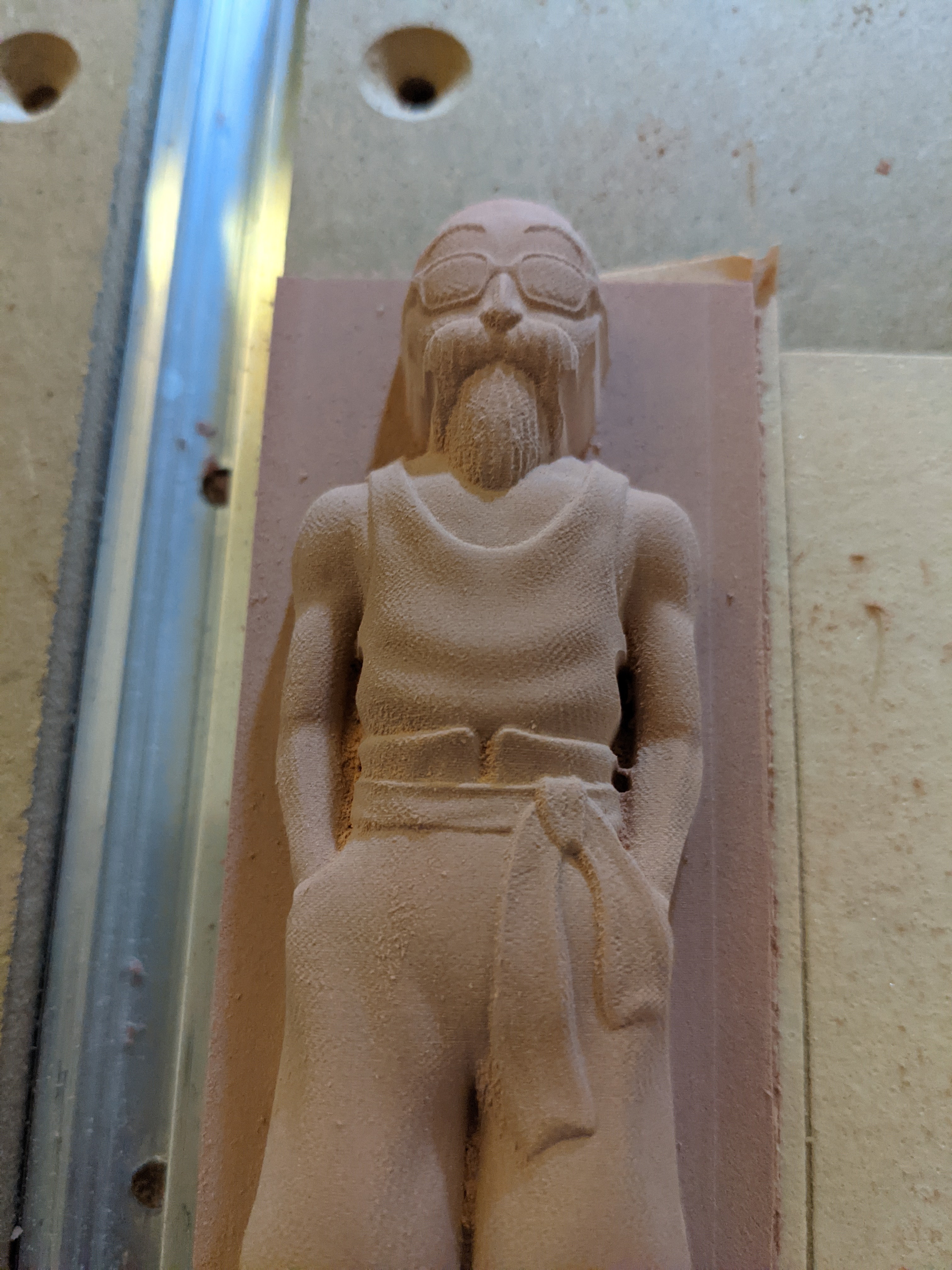
For this tutorial, instead of the STL of a heart (which I’ve cut too many times already) I decided to try something different, a model of “Roshi”:
Now I don’t actually know what a Roshi is, but this model is very detailed and very cut-able as indicated by the “no supports” in the description.
The model is so detailed (in the “many triangles” sense) with a 117Mb file size, that it runs near the limits of the software I’m using in this tutorial. If one were to go even more detailed, one might need to go to commercial software options. (I wonder if @wmoy or another Fusion wizard could do a similar tutorial on how to cut a detailed model like this with Fusion360)
Anyway, we have the STL downloaded, time for the next step
Step 2) Converting the STL to a grayscale height map PNG
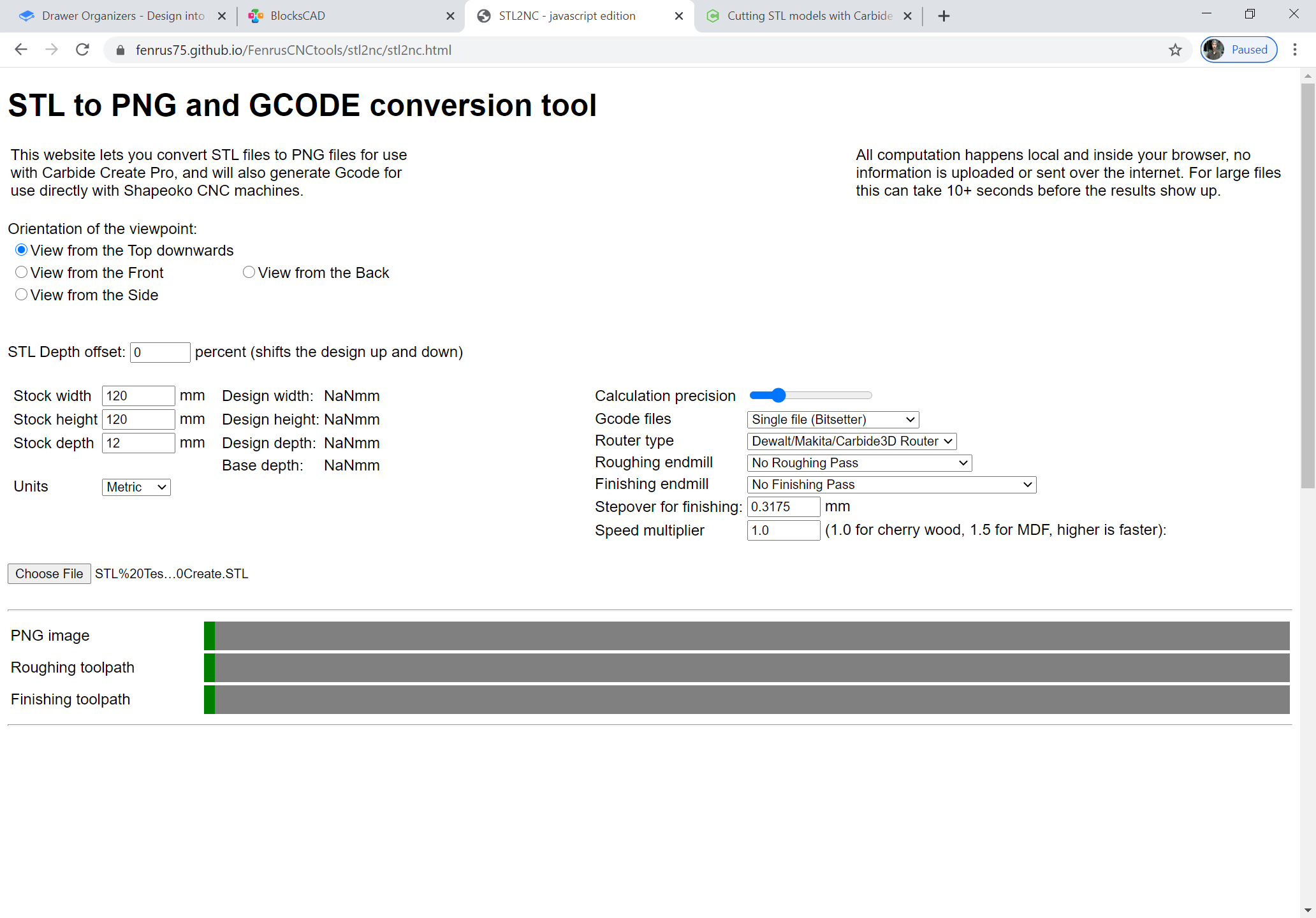
I’m biased but for converting STL files to grayscale PNGs I use the browser based tool I created at https://fenrus75.github.io/FenrusCNCtools/stl2nc/stl2nc.html . (It’s browser based, but not server based. All operations happen on your local computer inside the browser, nothing is uploaded or processed on the server… it’s just that a browser app means you do not need to install any software on your computer)
The webpage will look like this and below the image we’ll walk through the key settings:
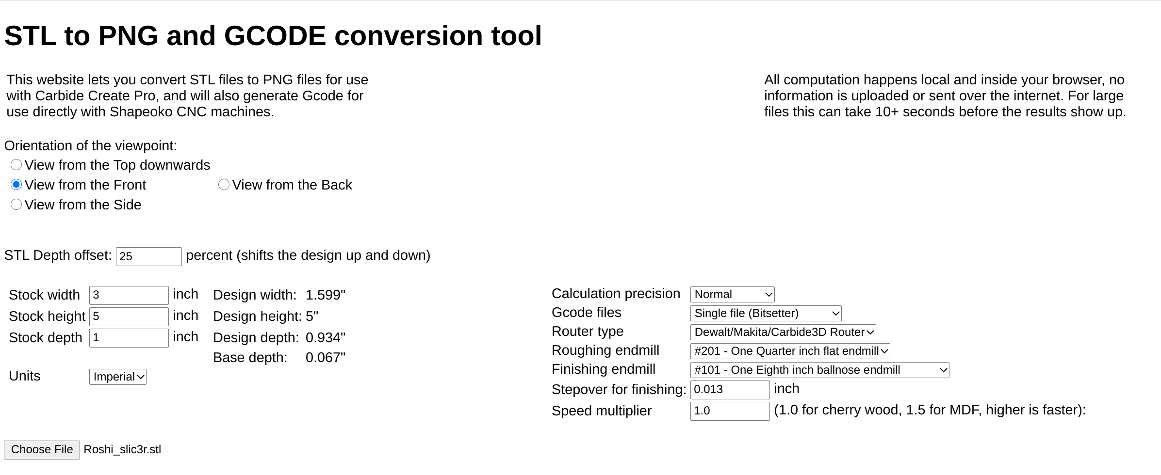
For this tutorial, only the settings on the left half of the screen matter (the right half settings are for generating gcode directly for the STL file, and are out of scope for this tutorial)
The orientation viewpoint is on its face simple; The model on thingiverse is “standing up” so we need to cut it looking at it from the front. If this was a landscape or similar model, we’d look at those models from the top.
The depth offset field (which defaults to 0) I have set to 30%. What this does is “sink” the model 30% into the base. For “people like things” that’s usually a good default; because we cannot cut below an “overhang” with a 3 axis CNC, it generally looks better to have the back part of the model not be in the design. (you can try it, what you’ll get is pure vertical “walls” from the widest part of the model down)
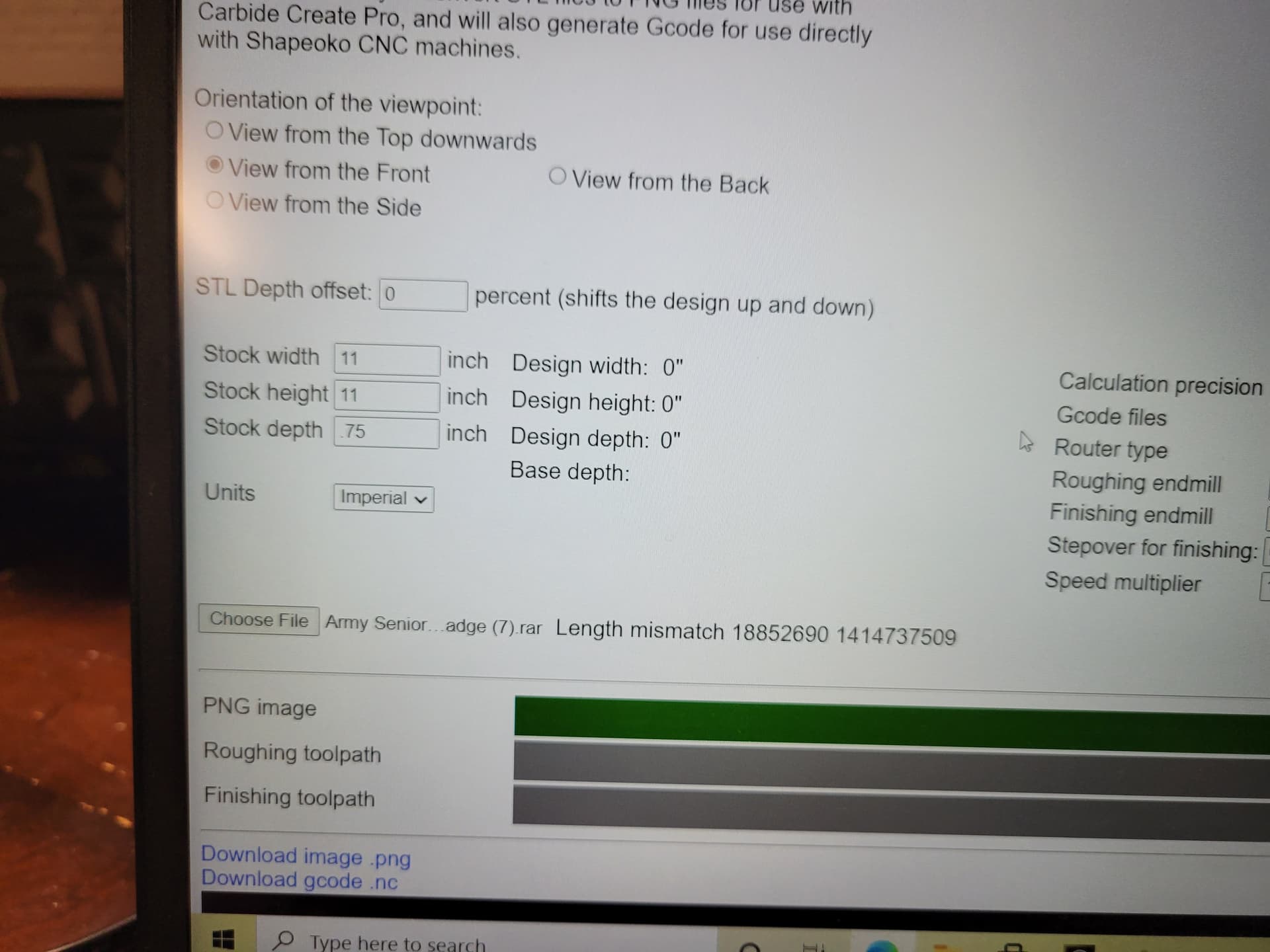
The next four fields are obvious; I plan to cut this model out of a 3x5x1" piece of renshape (https://shop.carbide3d.com/collections/materials/products/3x5-synthetic-wood-qty-5?variant=928094063) so I flipped the units to inches, and put in the 3, 5 and 1. (the STL model is “tall” not “wide” so I did 3x5 and not 5x3)
After that I loaded the STL file, waited a bit (the huge file is at the edge of the limits of the tool) and the tool updated the actual size of the model in the Design width/height/depth lines on the page.
The tool will make the model as large as possible as fits in the stock you specified, while keeping the aspect ratio of the model identical. In this case, my stock is wider than needed and in the Z direction a little bit is left behind (0.067").
Important: All four of these numbers we will use in later steps, so keep them around (keep the page open or cut and paste them somewhere).
The tool then calculates the PNG file (and gcode) which you can download with the link on the page that is shown once the calculation is done:
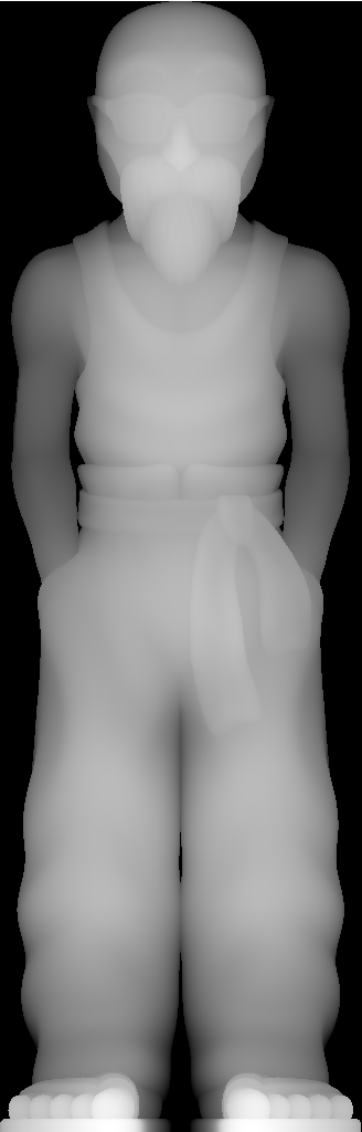
This PNG file is what we will use in Carbide Create Pro in the later steps.
Step 3: Carbide Create Pro - Basic setup
If you don’t have the Pro features enabled yet, go to https://launch.carbide3d.com/promo to request a one year free activation code.
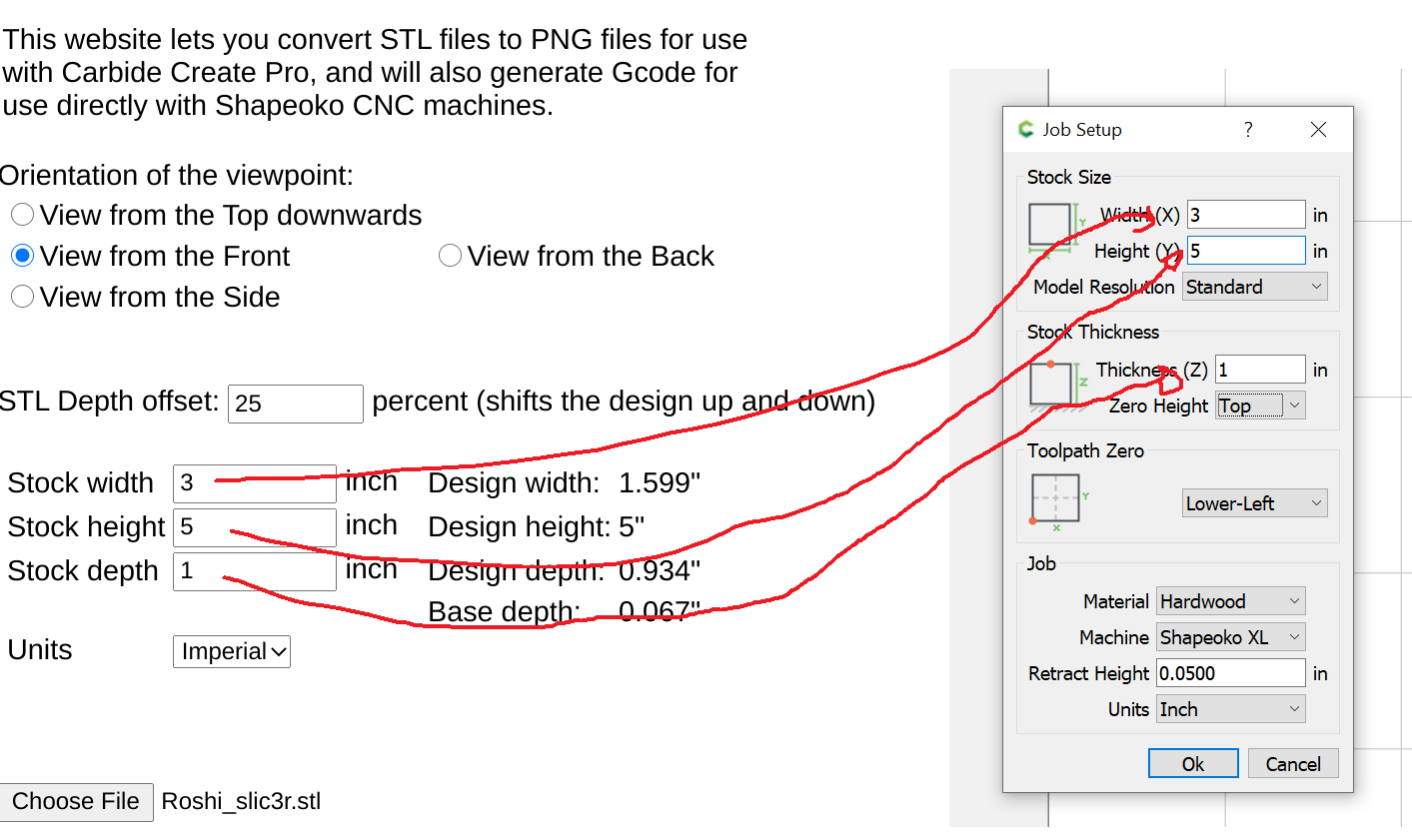
The first pat in Carbide Create is setting up the stock using the “Sprocket” job setup button. Here we use the same dimensions we put into the webpage:
Then we need to create a rectangle that will hold all our work and toolpaths, and this needs to be the size of the actual design, as printed by the webpage:
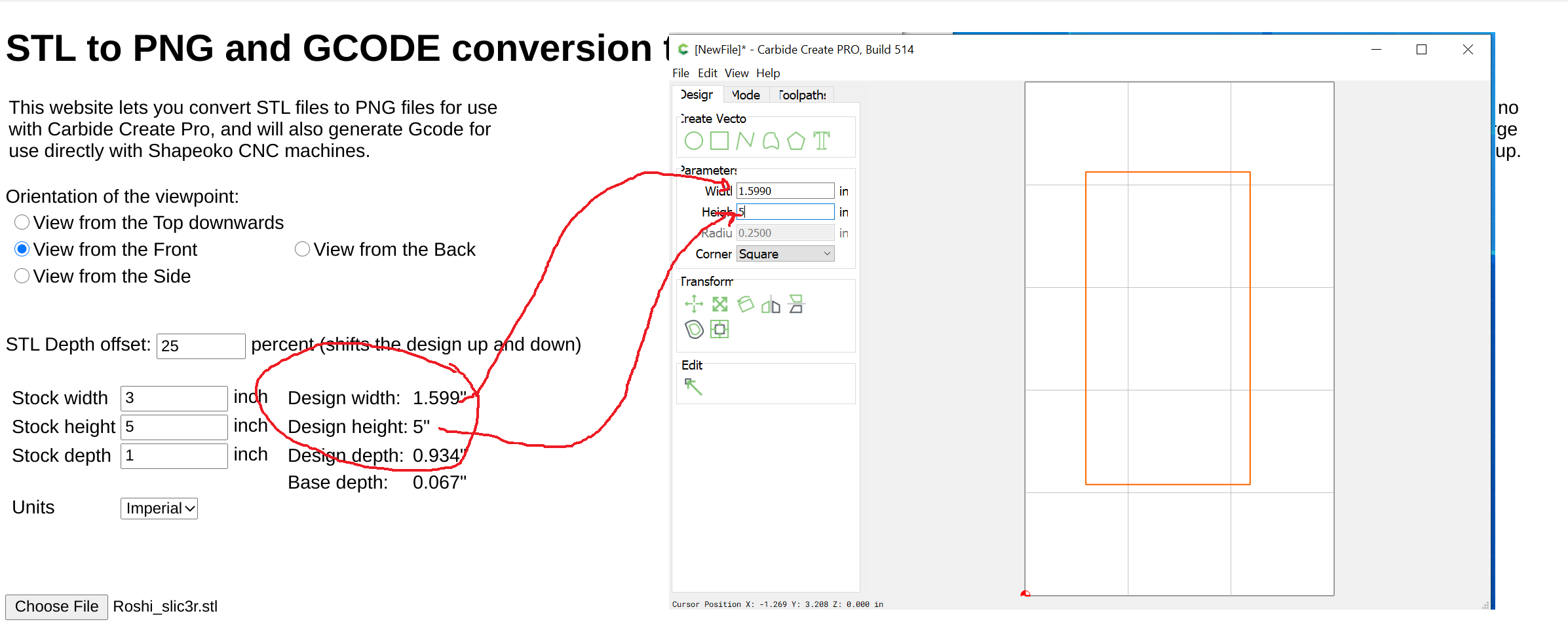
And after the size is set, for this tutorial, I moved the square to the bottom left corner of the design space.
Step 4: The “Model” tab
In Carbide Create, keep the square selected and go to the Model tab
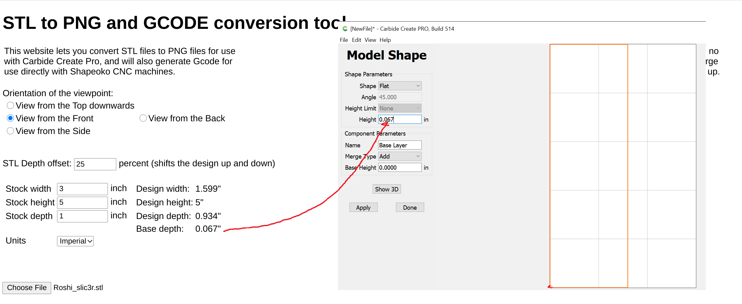
As a first step in the model, we need to put down a base layer that will be underneath the model (so that the base layer height + model height add up to the total stock height).
You do this by hitting the Solid Shape button

This needs to be a flat shape, with the height coming from the “base depth” field on the web page:
once the base layer is set, we’re going to import our PNG file using the Import Image button:

In the file dialog, we select the PNG file we saved in step 2
Then we need to put the height from the webpage into the fields like this:
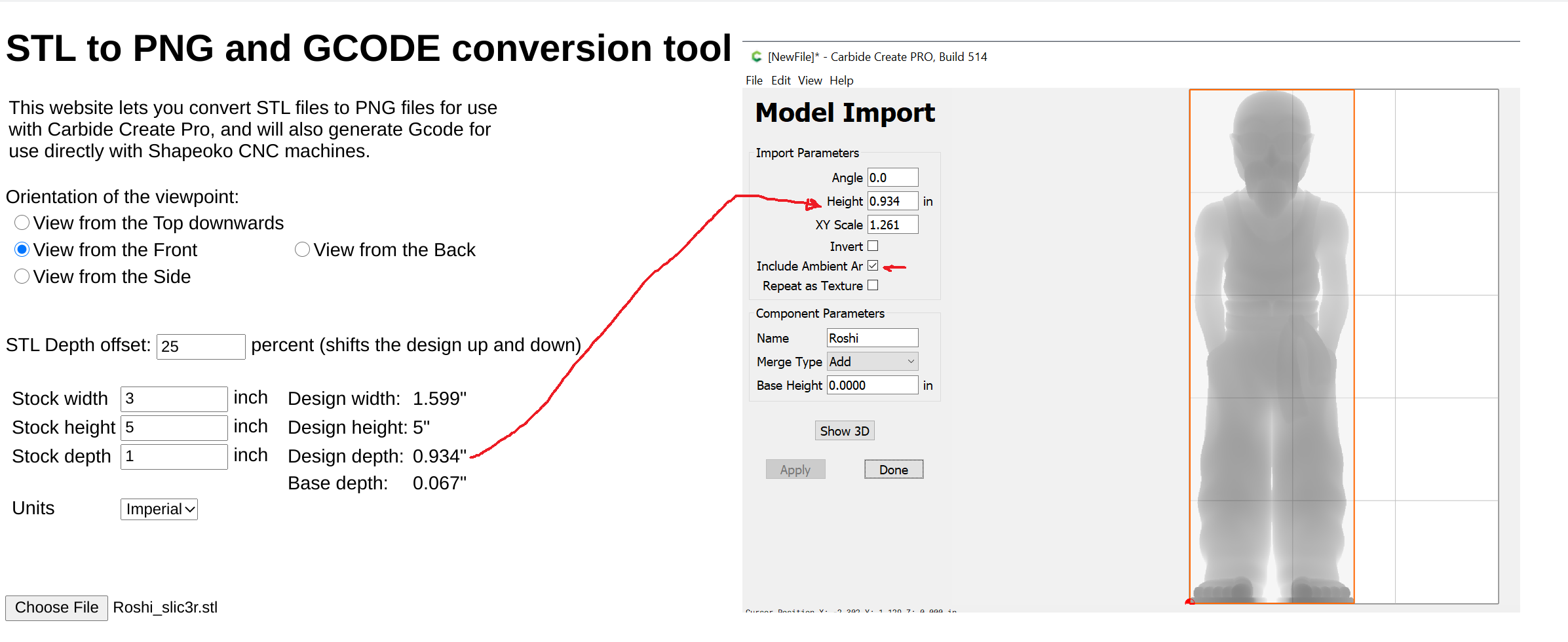
Hit the “Done” button and with that, we have finalized the 3D modeling step
Step 5 - Carbide Create Pro toolpaths
Keep the outer rectangle selected, and go to the “Toolpaths” tab.
We are going to make 2 separate toolpaths, one toolpath (called “Roughing”) that will use the #201 quarter inch bit to remove most of the material, and then a Finishing toolpath with a much finer bit to create all the fine details.
Step 5a - Roughing
In the toolpath tab, there is a “3D Roughing” button… select that and the dialog box will look like this:
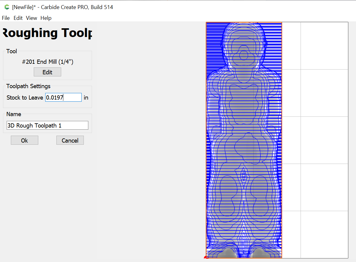
Make sure the #201 bit is selected, but for the rest, the defaults are just fine
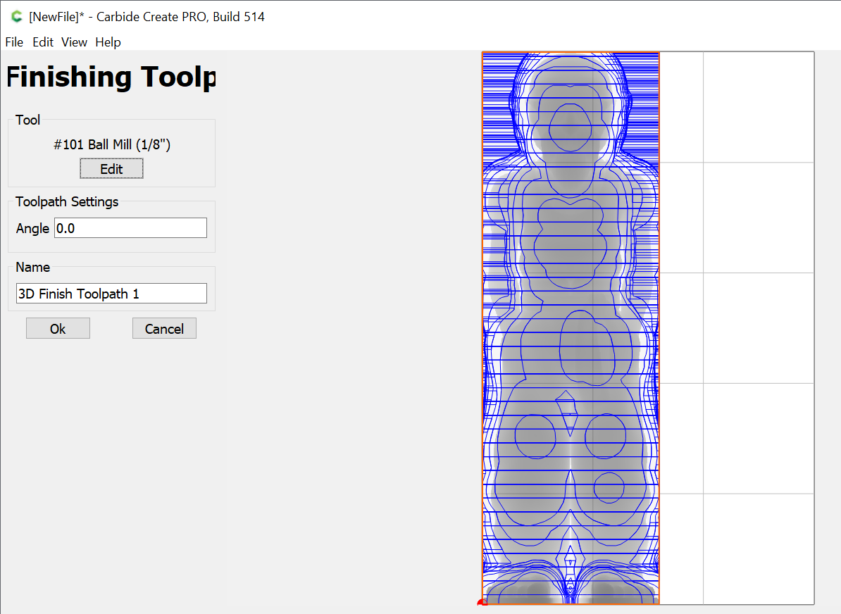
Step 5b - Finishing
Then select the “3D Finishing” button to create a finishing pass. In the screen below I picked bit #101, which is 1/8". For finishing it is often (but not always) best to use a ballnose bit. The smaller the bit the more accurate details you will retain.
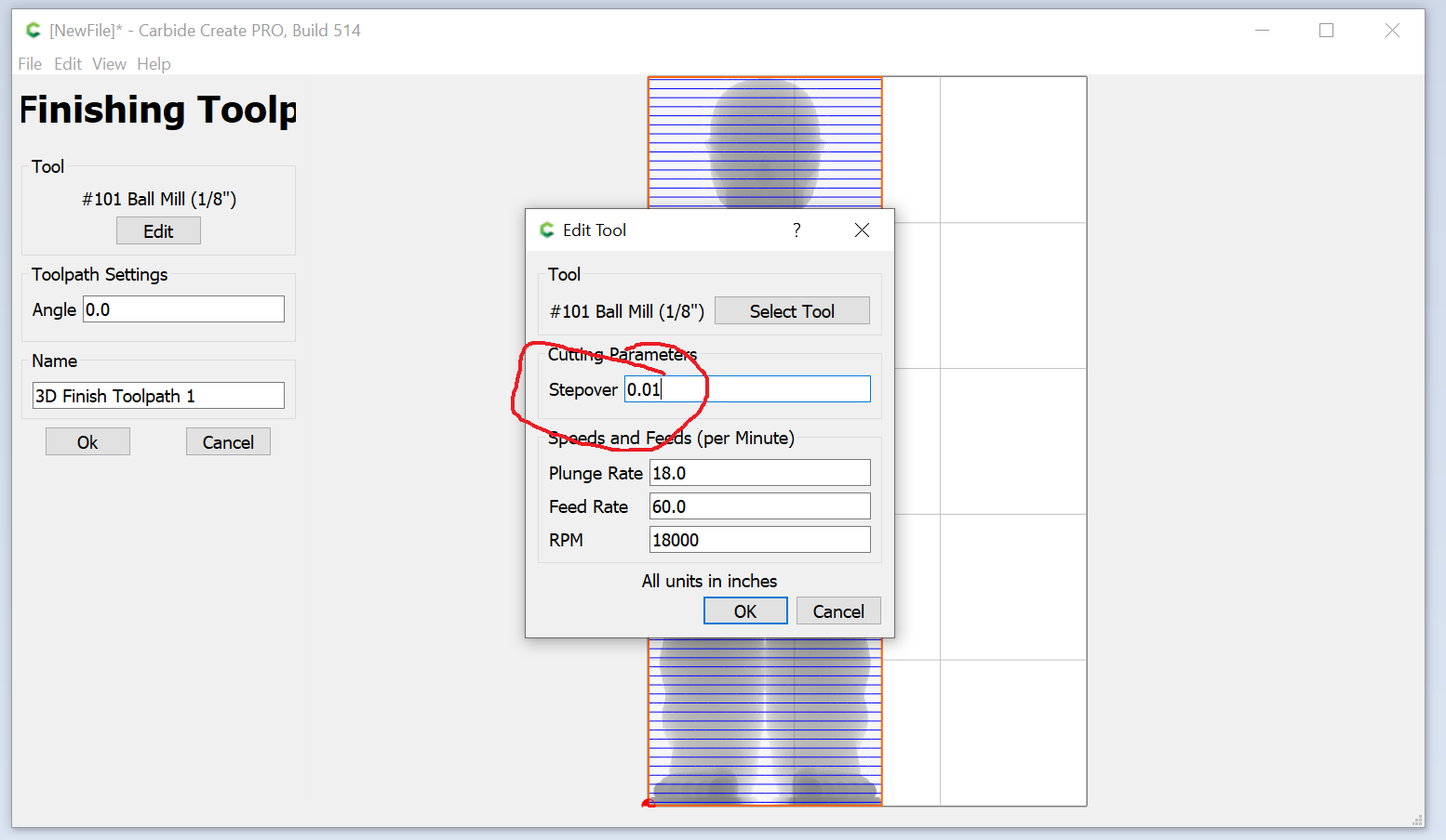
(In some very stringy wood, like basswood, I have found that using a small flat endmill works better than a ballnose)
To get a good quality result it is important to reduce the stepover away from the defaults to something much smaller (typical is 10% of endmill diameter):
Step 6: Save the gcode and cut using Carbide Motion
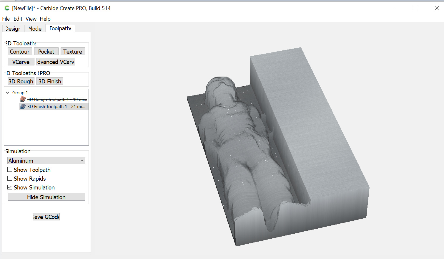
Step 6 and beyond are no different than any other design you do in Carbide Create: Save the gcode and use Carbide Motion to use your CNC machine to cut the design out of wood.
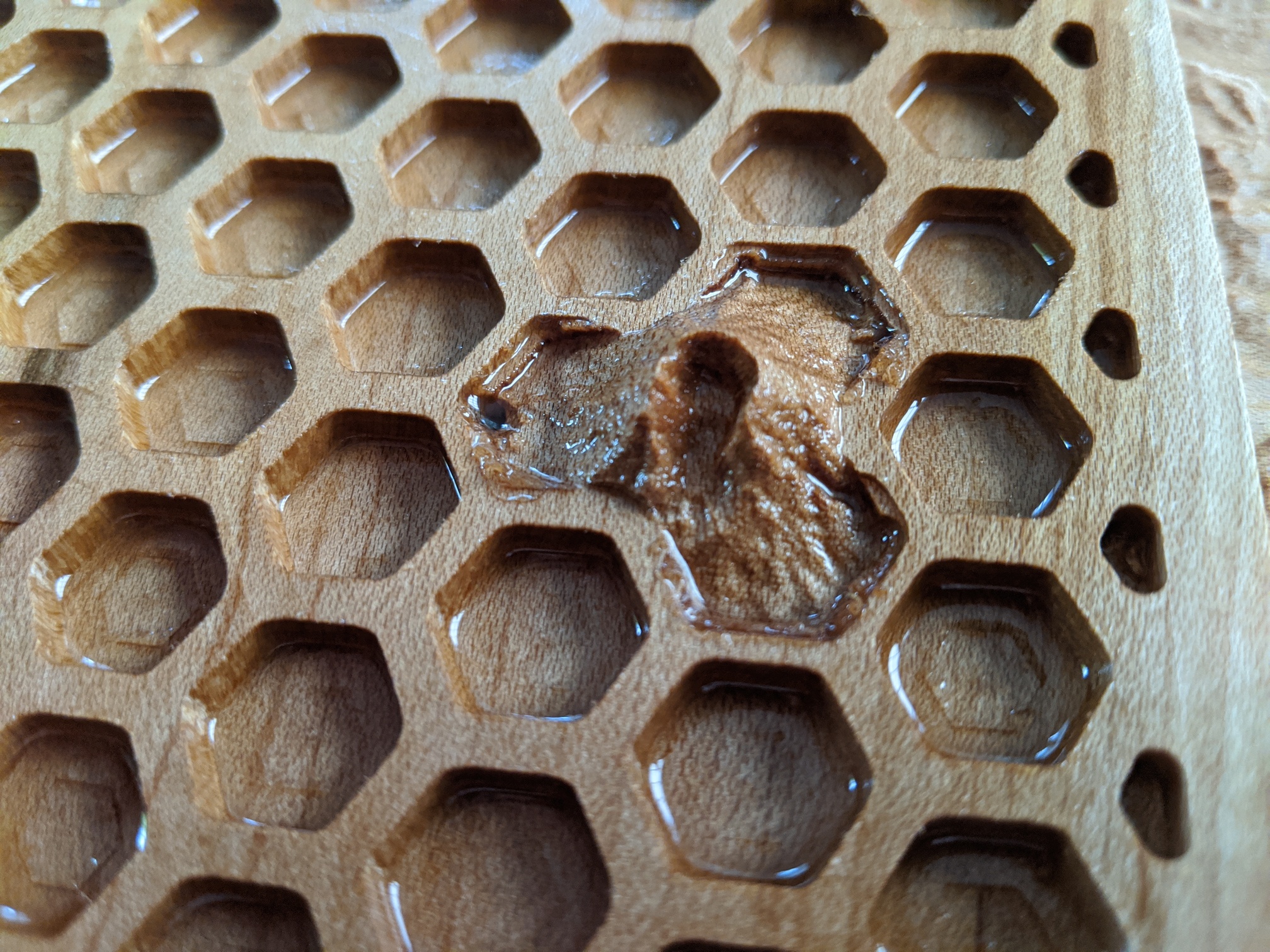
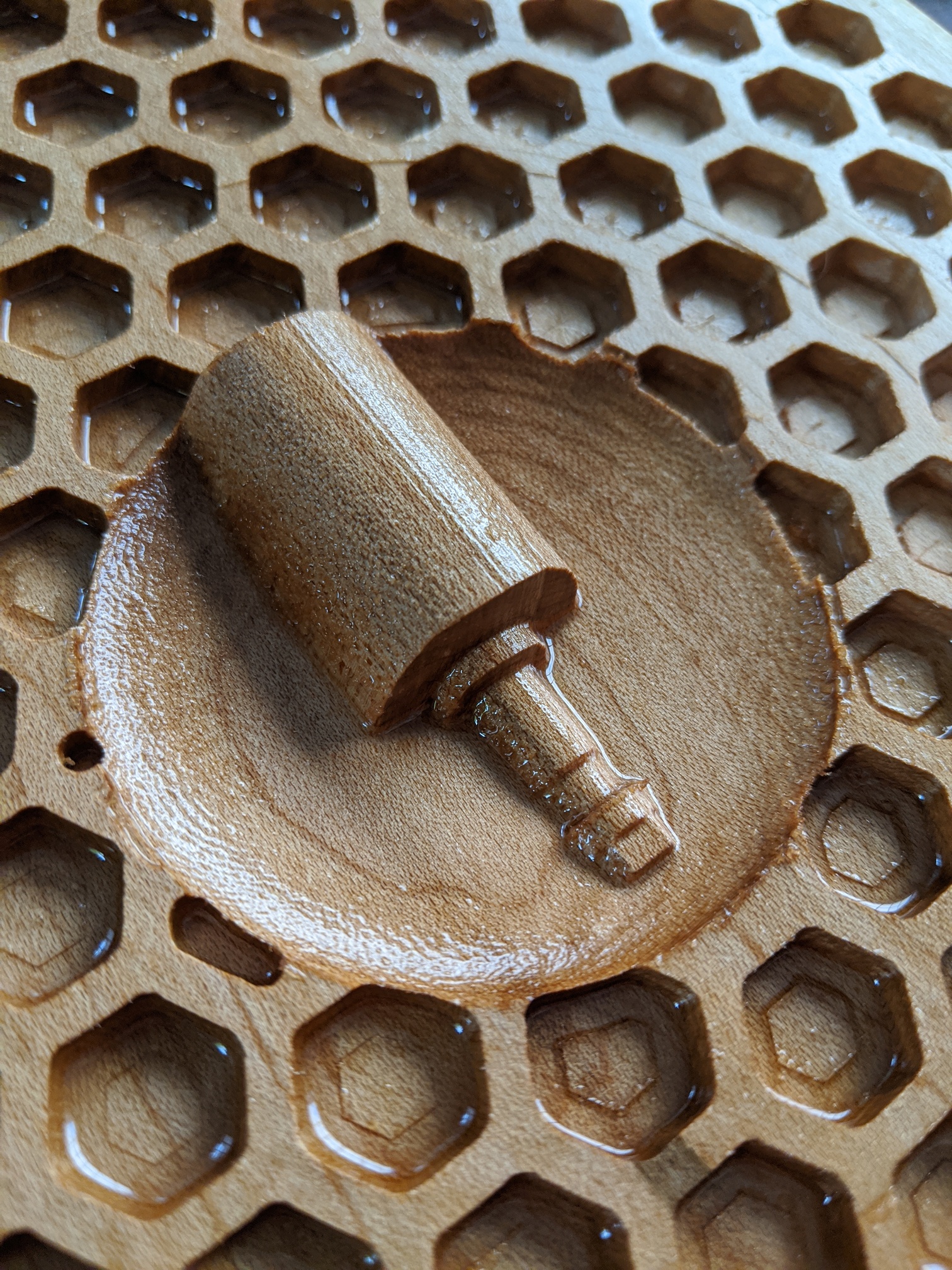
Final observations
I actually used a “tapered ballnose bit” for the model I cut out in the picture; Tapered bits like https://smile.amazon.com/gp/product/B015C61XX4 are great because they are sturdy (you can cut fast) while very detailed. Only gotcha is that they usually advertise a ball radius not a ball diameter.
Renshape is really great to cut, it cuts as soft as MDF but without the dust and with much much better ability to retain details.