Test cuts with the newly installed spindle

So I finally got tired of the Dewalt Router and it’s wobble on the axis and the need to replace brushes all the time and installed a nice water cooled spindle. I figured 800W is plenty for what I use it for…
Also got a matching 65MM diameter HD spindle mount from Carbide3D… that thing is SOLID and it looks like no tramming needed kind of precision.

After I installed everything, made some mistakes, ordered some replacement parts … time to make some test cuts.

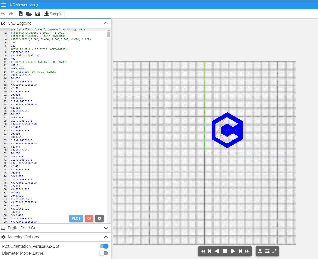
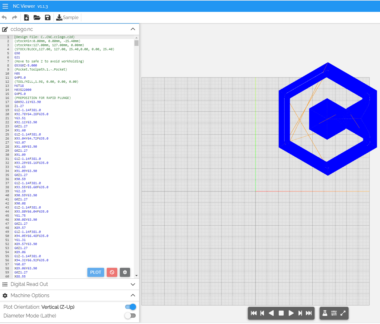
Step 1: Basic 2D “hello world” kind of cut

Simple Carbide3D logo, drawn in Carbide Create and cut with one of my favorites, a 2mm downcut endmill

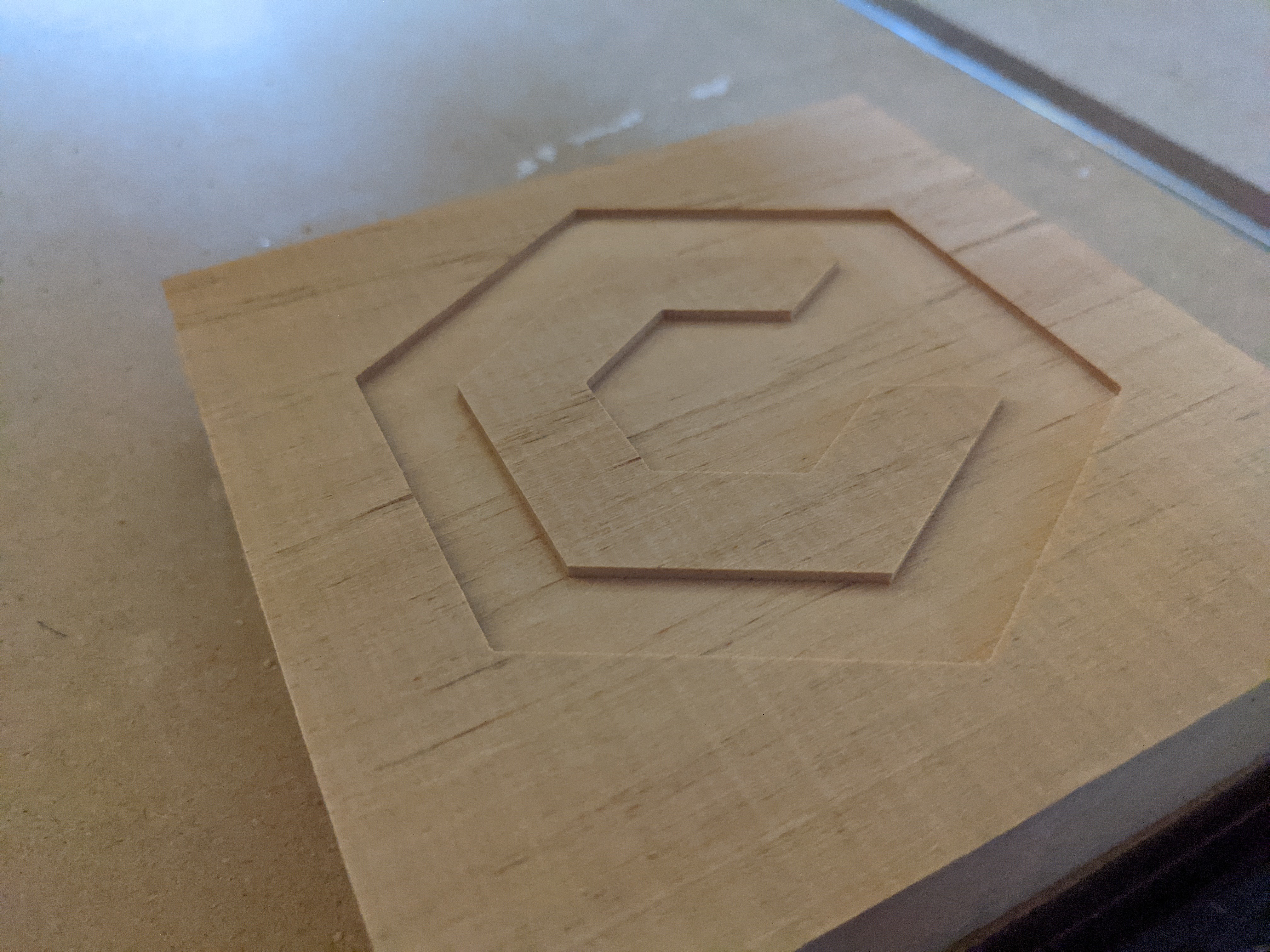
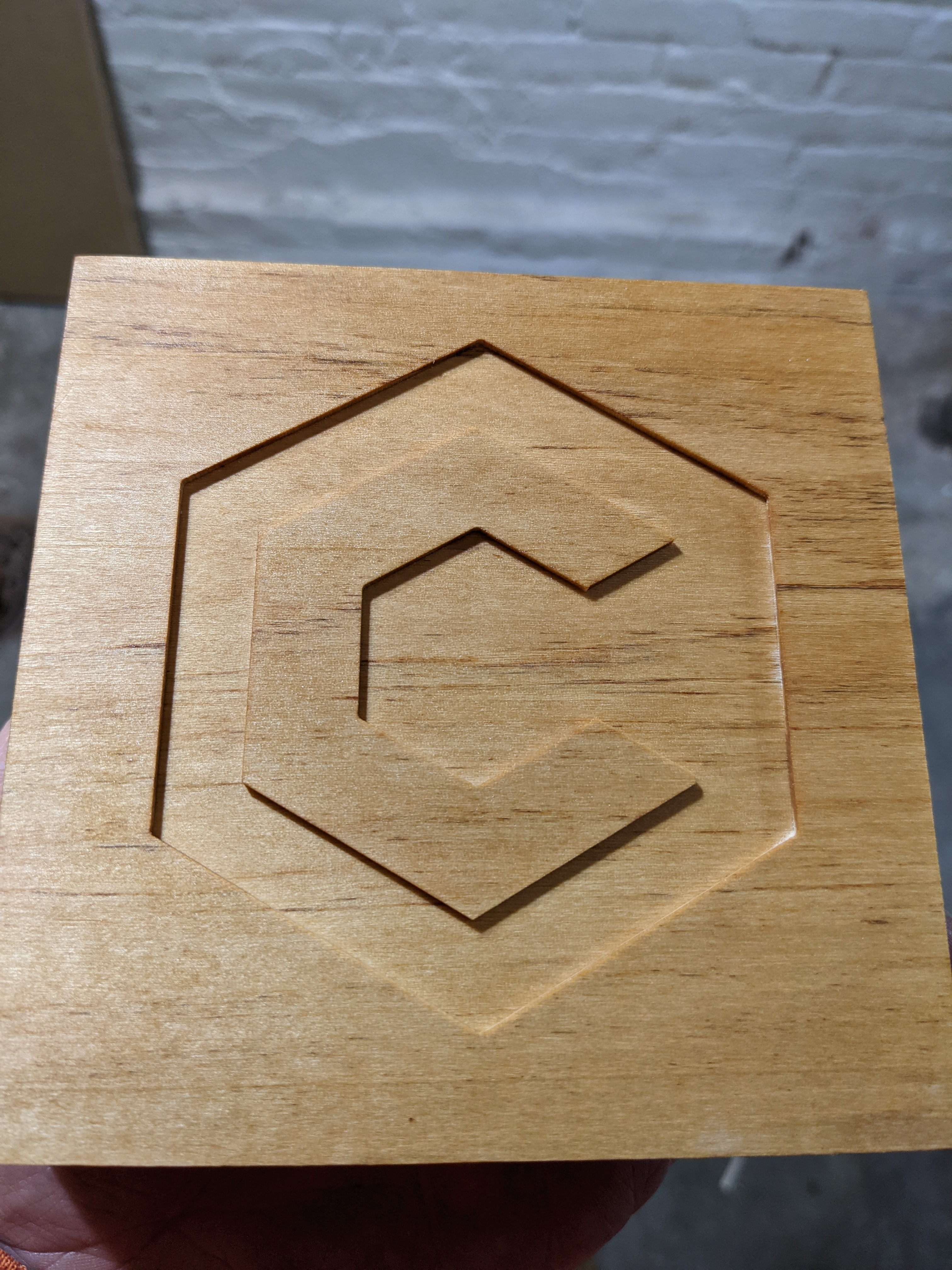
Result: Very nice. The pockets are SMOOTH. No tramming needed. Love the spindle (quiet!) love the 65MM HD Mount

Gcode: cclogo.nc (86.5 KB)

Step 2: Basic 3D cut from a STL file

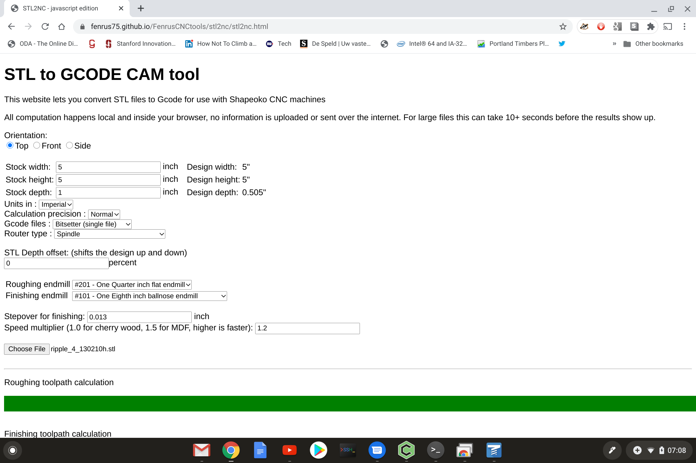
Grab an STL from thingiverse (https://www.thingiverse.com/thing:50851), add spindle support to gcode converter, convert to gcode (https://fenrus75.github.io/FenrusCNCtools/stl2nc/stl2nc.html of course) and cut out of 5x5 basewood, while cheaping on time with a 1/8" bit and too big stepover. Bad mistake. Basewood is too stringly to get nice 3D cuts… but that is for next time

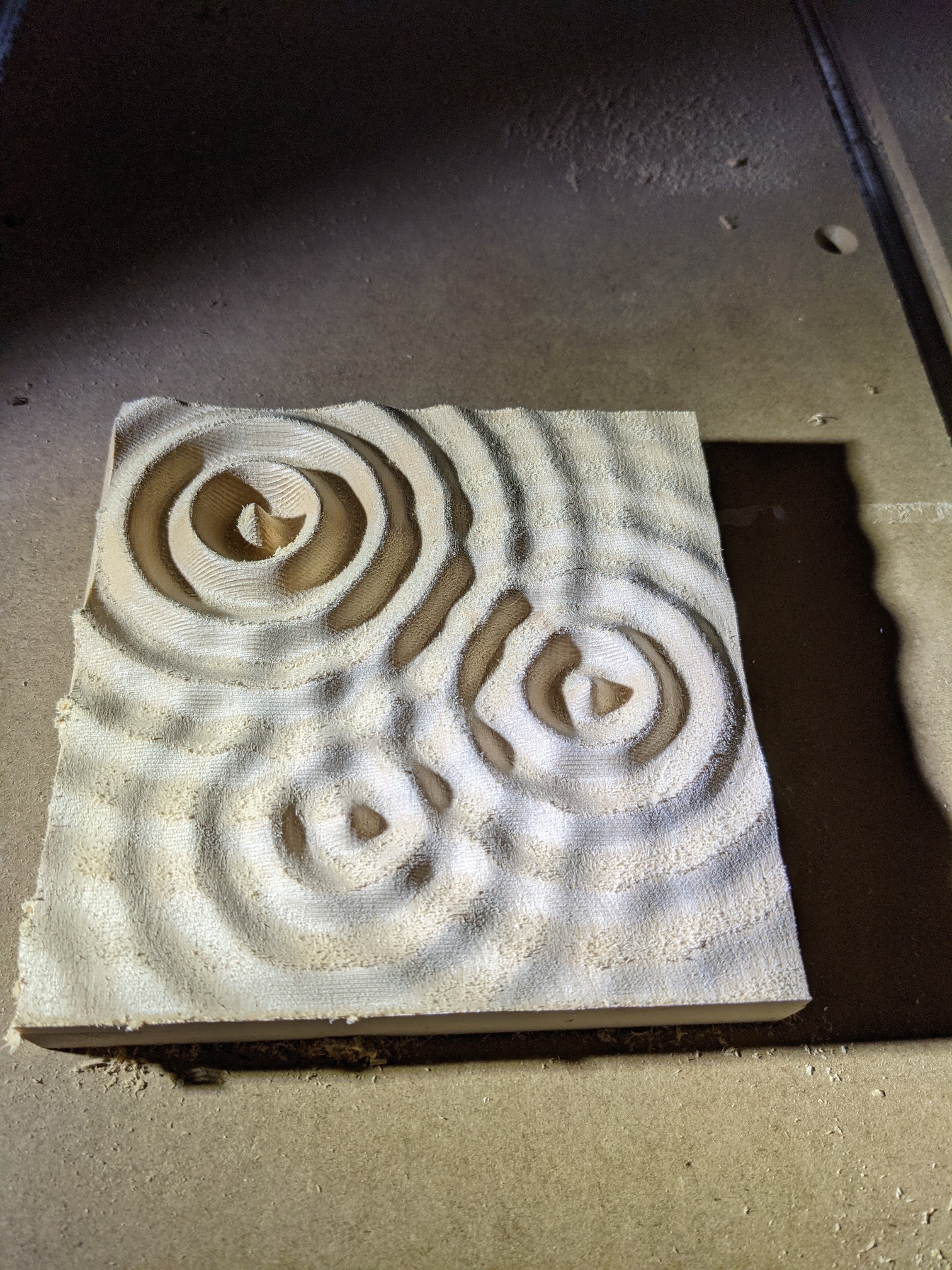
Gcode: ripple_4_130210h.stl (1).nc (2.0 MB)

Step 3: it’s Friday night

So it’s Friday night, and I’m sure everyone else by now is also asking themselves: This was boring. Can we cut the 2D gcode from step 1 right on top of these 3D ripples?
(well maybe you don’t. But I did. It’s been a long week at work)


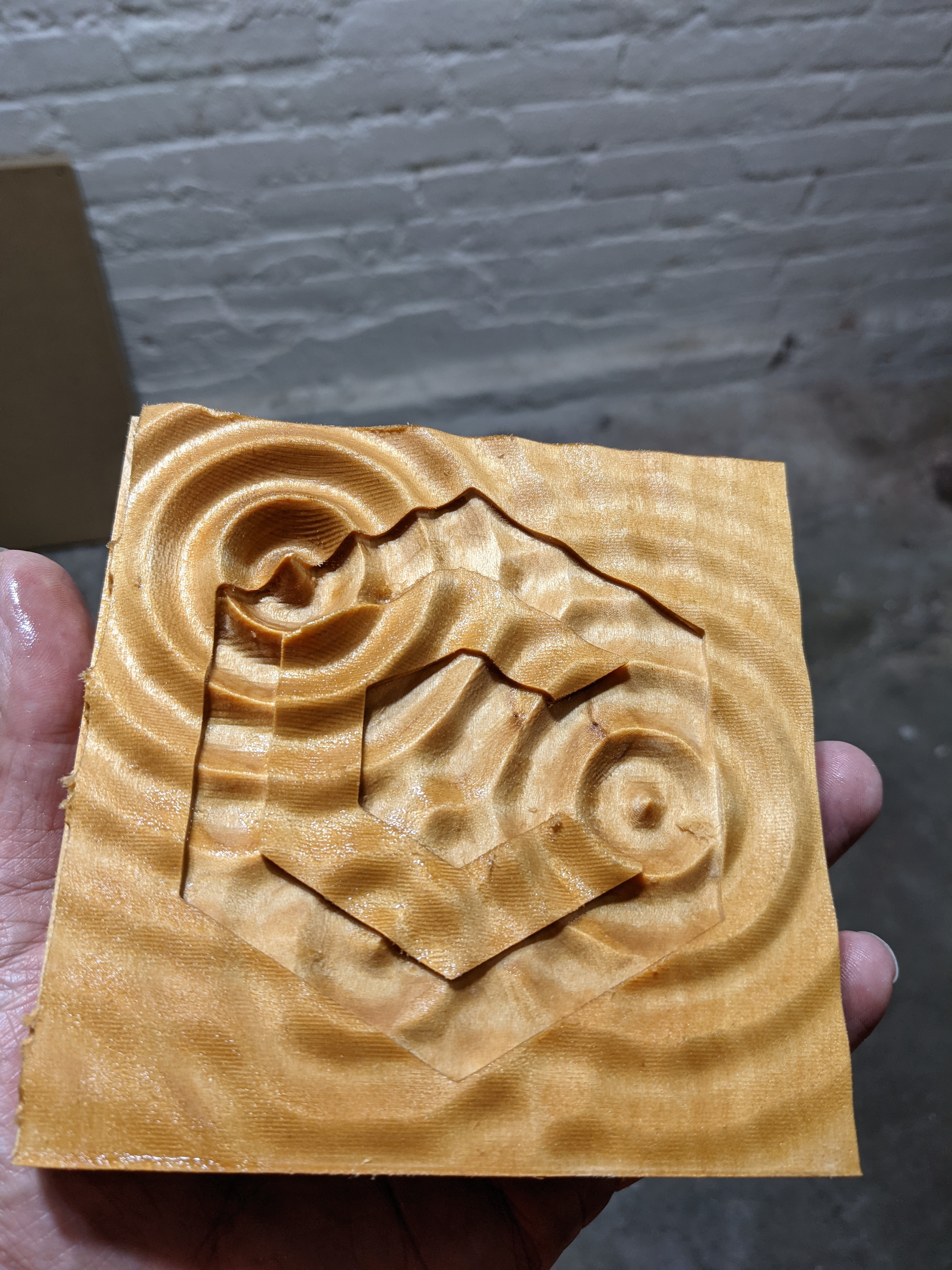
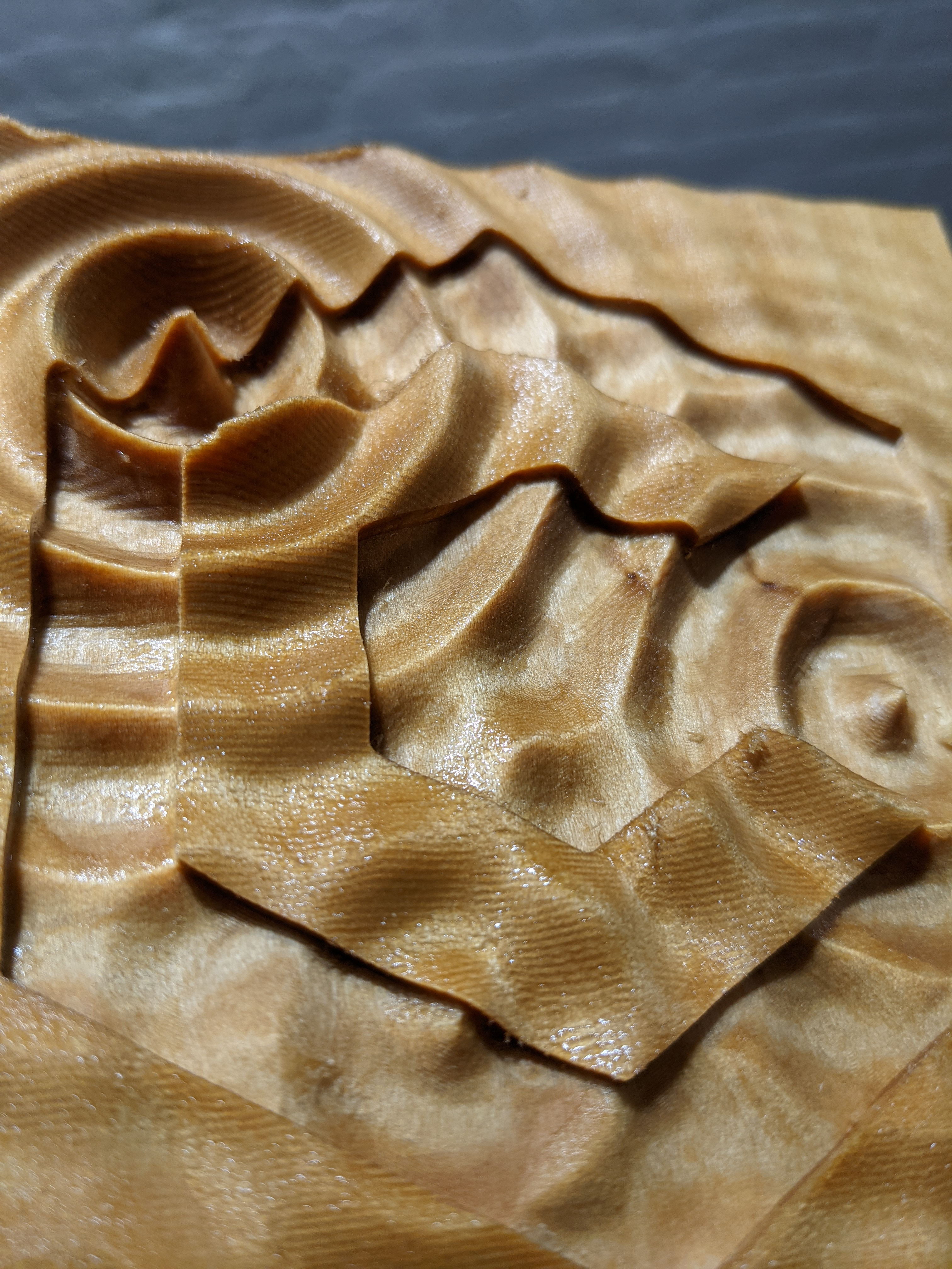
The answer is: Yes you can. Maybe you shouldn’t, but you can.

All kidding aside, in 3D vector tool path @ads wondered if one could use 2D toolpaths to cut roads into 3D landscapes and well, yes you should be able to.
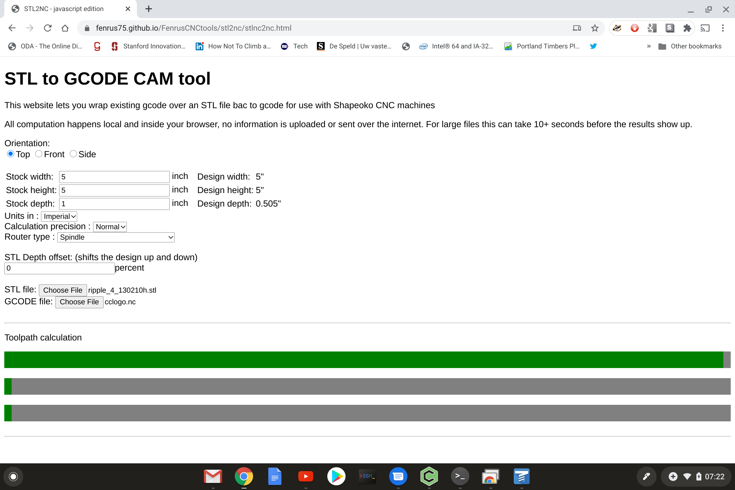
It’s just a matter of modulating the Z elements of the Gcode to the underlying 3D model (bla bla more digital software gunk here).
For example, the gcode from step 1 above, after modulation, looks like this: cclogo2.nc (2.5 MB)

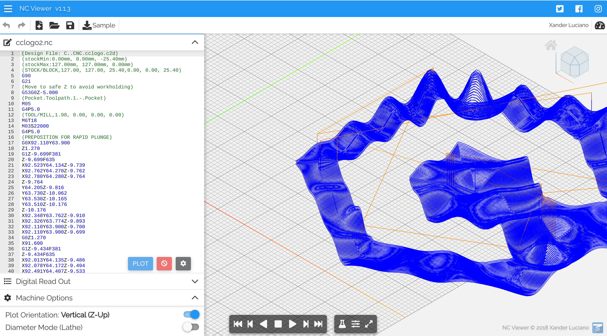
This will work for any STL file, overlaying any gcode that carbide create will generate…

13 Likes

Pretty cool [digital software gunk] and result!
Will you be integrating that feature in your G-code toolsuite ?

1 Like

yeah it’s basically all the same core library code just with a slightly different front end that asks for 2 files instead of one. I’ll post a howto here after breakfast and I need to figure out if I can merge the GUI sensibly into one tool or of it’s going to stay 2 separate end user tools (sharing 99% of the code)

7 Likes

Simple-ish howto what I did to create the “cut gcode into a 3d carve”. Note all this assumes you have a bitsetter; there is no good way to re-set the zero point for bit lengths without it since the 3D carving will most likely cut away the place you set the zero.

Step 1: Create the gcode to do the normal 3D carve using the online tool

https://fenrus75.github.io/FenrusCNCtools/stl2nc/stl2nc.html

Set the basic parameters; my stock was 5"x5" so I switched to empire units, selected the spindle over the router (this pauses after tool change) and I picked the 1/8" ballnose endmill for the finishing pass (which is coarse but it was Friday evening and I was time limited). Load the STL file using the “Choose File” button and … wait a few seconds (gcode generation is not all THAT time consuming)

Save the gcode by clicking the download link:

Step 2: Do the 3D carve

Just load the downloaded gcode in Carbide Motion and watch the zigzags

Don’t remove the work from the machine, it’s important to keep the same zero position of the machine so that you can overcarve the 2D design using the exact same coordinates

Step 3: Create the 2D (or 2 1/2D) design in Carbide Create

Nothing complicated here, but it works best if you set the dimensions of the workplace are set to the same dimensions as put in the online tool at step 1. Also it’s required to use “zero at top” for the coordinate system.
Carbide Create is not strictly required; any gcode will work with the current limitation that I haven’t activated support for G2/G3 arcs in the tool. (not complicated to add, I have previously created the library functions for it, but I have no tools that create gcode for testing with these so I disabled for now)

For best results in terms of quality, use a smaller stepover than you would normally do; 10% to 20% seemed to work great for me.

Step 4: Create the overlay gcode

Go to https://fenrus75.github.io/FenrusCNCtools/stl2nc/stlnc2nc.html (different URL than before) and fill in the fields.
It’s important to use the same dimensions as you did in step 1 … otherwise things will not align right.


Then you load the same STL file as in step 1, and with the second Choose File button, you load the Gcode you created in step 3.

Wait a few seconds (should not take super long) and you can then download the overlay gcode, which is the gcode you loaded, but with the Z component of the paths offset with the height data from the STL… o
(If the gcode has long distance G1 commands, don’t worry, those get broken up into small segments where each segment gets its own Z offset)

Step 5: Carve this overlay

Carbide Motion, don’t change any zero or other offsets… just load and run

8 Likes

afterthought: As much as I said “use zero at top” I realize you can create a pretty cool effect with “zero at bottom”… skip the whole regular 3D carving paths (step 1 and 2) and in Carbide Create, do a “zero at bottom”. But in Carbide motion, you zero the machine at the top.

What this will do is basically only cut into the material the shape you have, exposing the 3D carved relief, while leaving all the places you don’t cut as is…

2 Likes

Can get this to work great with another STL file and the CClogo.nc file you provided. However struggling with getting it to work with a gcode file I create from Carbide Create. Any chance you could also share the CClogo file for Carbide Create so I can compare your Carrbide Create settings to mine to see where i went wrong?

Thanks

cclogo.c2d (22.1 KB)

no problem

also be happy to debug anything else but would need a nc file

(I’ll admit that this additional tool was “good enough” for me at some point… and I made the cut for this topic… I did not do super extensive testing with other files)

If i create gcode from your cclogo.c2d file I get this. Used build 464. C3D Logo.nc (85.3 KB)

While your gcode is larger.

Should I be using metric or inches as my code looks to be g20 while yours is g21?

eh metric I suppose; I have not used the empire version of the post processor settings.

Now that I have the the empire version of the gcode I can likely fix the tool to make it work with that :wink:

(EDIT: missed your link,… working on debugging this now)

ok indeed it was a metric/inches issue… all the math was done in mm even if it was inches.
I just fixed that as far as I can tell…
(by converting back and forth a bunch)

the website should either have been updated already or update in a minute or two, depending on github propagation delays

1 Like

Just created another file and started running it. So far so good :smiley: looks like it is following the ripples perfect!

thanks for the report … seems you did just about all the debug for me :wink:

@fenrus Thanks for the work! Been thinking about it off and on all week. I’d made it half-way or so through Terrain Relief Models, Unabridged but this version might open up even more options. One option is that it allows the creation of inlays with a non-flat top surface. Think v-groove following a ripple. I was thinking through the tool-chain earlier, and I think you could use the online tool you’ve created to make the initial height map, then bring that height map into Blender to create an STL. Using booleans you could then make a negative of the STL, machine both parts out of separate materials, glue them together, and then machine off the top to create the non-flat surface. There might also be a (simpler) way to do it without using Blender, and working entirely from height maps, and color inversions.

It probably makes more sense in my head than in the paragraph above, but given the time I have to commit to these sorts of things, it’ll take me a while to get a proof-of-concept together.

Thanks again for making this tool. It’s a big help.

there is a thing called Blender-GIS that can import geo data straight into blender. It’s a bit hard to use, but there’s youtube videos for it that I managed to follow as a blender-noob.
(enough to make Cityscape of Portland OR )

interesting mention since in theory one should be able to do rivers or roads or other type of features with different color wood. ho hum . that’ll be a fun challenge

That’s the line I was thinking. With the positive and negative, you could embed inlays / compass rose / trails / labels into topographic maps. I used Blender quite a bit years ago but haven’t done much with it in a while. Haven’t heard of Blender-GIS. Even so, I’m not sure off-setting things like V-carving relative to the topographic surface would be straight-forward within Blender itself, but others would have better expertise there.

One element I’ve been thinking through is how to offset the initial topographic layer so that, coming back to clean things up, you can create a new layer ~2 mm lower to avoid any artifacts from running the mill on almost the same topography twice. I think you could do it by just oversizing the inlays, but it would take more tinkering.

A simpler approach would be to do all the offsetting as your tool allows, seal the surface, paint the v-groove or other features, and then (since you can’t sand the paint over-spray off) come back and take another 0.020" off to remove any paint over-spray. This would just require oversizing the lettering or other graphics by a small amount so they are the right size after skim cutting the surface again.