Terrain Relief Models, Unabridged

Terrain Relief Models, Unabridged

When I was musing about picking up a Shapeoko, the project I had in mind was carving a terrain relief model of Mount LeConte in the Smokies, and in my head I also had the trails engraved onto the model. In the quest to make this thing in my head a reality, I followed various trailblazers, perfected workflows, had epiphanies, scrapped entire workflows, wrote some plugins, added a laser, and eventually arrived at what seems to me like a perfectly cromulent (albeit not perfect) workflow. So, this is not to say that mine is the workflow everyone should follow, but by documenting it in glorious detail, it is my intention to show a workflow that can either be followed directly or simply used as a reference for exploring alternate approaches.
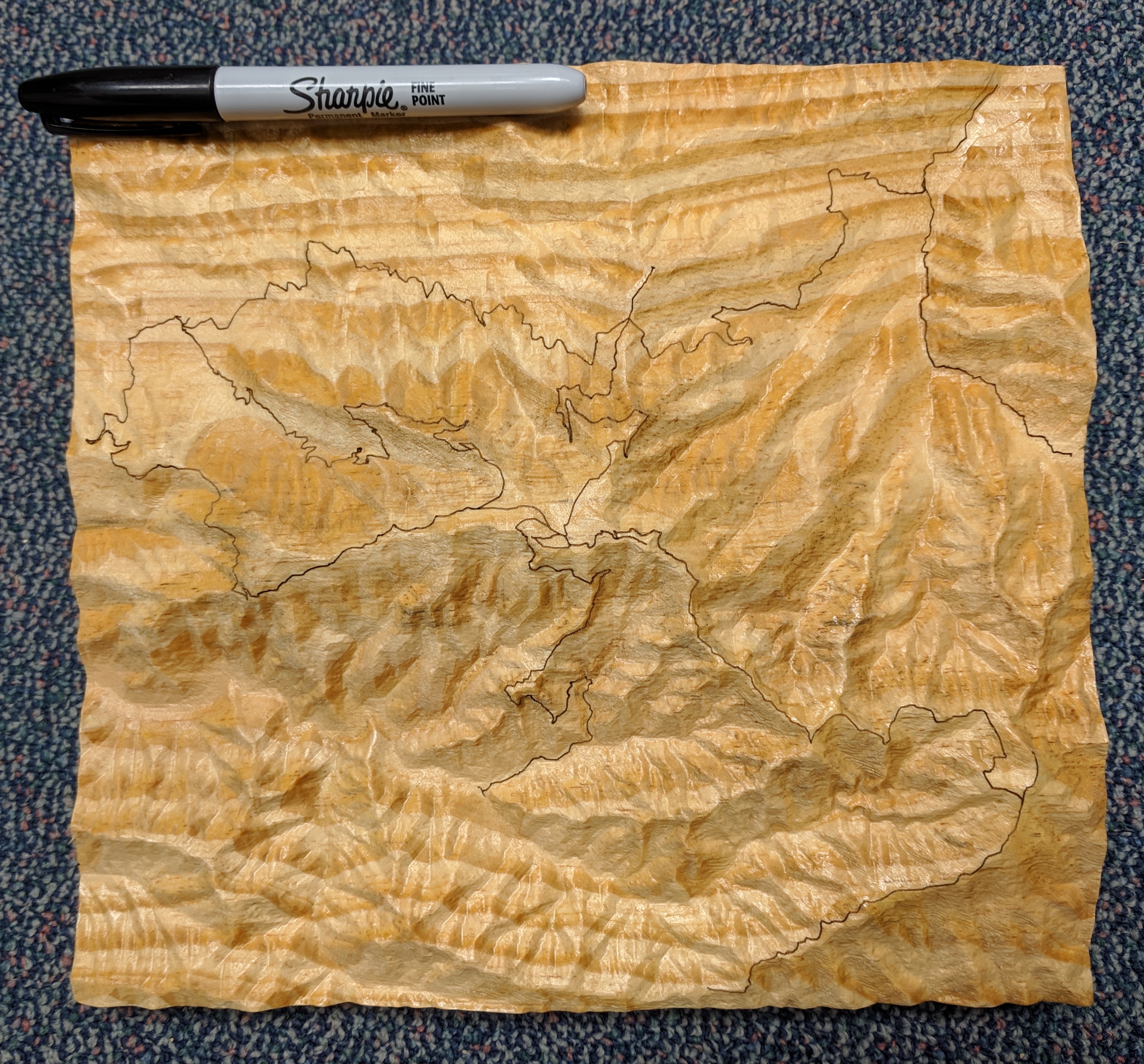
Table of Contents

Workflow Summary

If you would like to engrave trails onto your model (or perhaps just carve a companion map), the italicized steps will be part of your workflow. If not, what italicized steps? I don’t see any italicized steps. :grin:

  • Define your model’s area of interest.
  • Download digital elevation model (DEM) data covering your area of interest.
  • Download or generate vector path data for your trails.
  • Process your DEM data in QGIS to yield just the data for your model.
  • Process your vector data in QGIS to yield just the data for your model.
  • Export a high-resolution 16-bit PNG heightmap of your model.
  • Export a DXF “pathmap” of your vector layer.
  • Process the heightmap using the CAM software you prefer for terrain models.
  • Process the pathmap and CAM that up, too.

Note on Tooling

I almost exclusively use 1/4" (6.35mm) tapered endmills for the finishing pass of my terrain relief models. My standard finishing tool is a tapered endmill with a 0.5mm radius tip and 31.75mm of flute length, giving it the quite desireable combination of carving quite fine detail with quite excellent reach. For my terrain relief models in southern yellow pine dimensional lumber (which has actually become my favorite medium for terrain relief models, go figure), the cheap ones on eBay or Amazon have been quite worthy additions. (If you’re making a model out of tropical hardwoods, you might want to spend a bit more.)

For roughing, I most often seem to use a basic 1/4" ball (e.g. the good old #202) with a very large stepover and a pretty deep depth. I set the roughing pass to leave a millimeter (plus the giant scalloping), and the finishing pass with the tapered endmill can basically go through the leftovers as fast as you want to drive it.

9 Likes

Software Choices and Setup

For creating terrain relief models, you will need to make a few software choices. Some of them are basically fait accompli – there’s effectively no alternative to QGIS that does not involve departing completely from this writeup (which you are, of course, free to do). Others are down to preference or availability – if you have a MeshCAM or Vectric Aspire license, there’s a good chance you might want to go that way with the CAM parts of the workflow. I’ve broken the software into three groups: software for processing the source GIS data (i.e. QGIS), software for machining terrain relief models, and software for engraving trails onto terrain relief models (which is completely optional, of course).

Processing the source data:

  • QGIS – Free and open source Geographic Information System software used for processing elevation data.
    • Heightmap Export plugin – QGIS plugin for easily exporting elevation data as high-resolution 16-bit PNG heightmaps.
  • Inkscape – Everyone’s favorite free and open source vector drawing program. In this case, used to take trails exported from QGIS as DXF files and turn them into properly rescaled usable SVGs (for engraving on your model or carving a companion map).

Machining your terrain model (choose any):

  • Image 2 Surface Add-In for Fusion 360 – Free and open source add-in to Fusion 360, but Fusion 360 does not handle large, high-resolution models well (if at all).
  • PixelCNC – Inexpensive (~$75) software for CNC from image (or STL) files. (Still some annoying quirks at its current version 1.33a, but very fast processing and very nice end results.)
  • Vectric PhotoVCarve – Somewhat more expensive (~$150) software that can carve based on a greyscale heightmap, but constraints make it a poor fit for terrain models (e.g. it does not appear you can make separate roughing and finishing jobs with different tools or use tapered endmills).
  • MeshCAM Standard – More expensive (~$250) software that really can handle STL files and heightmaps, and is included with the Nomad.
    • MeshCAM v6 was significantly slower (9 minutes vs. 14 seconds) generating toolpaths for my test project than PixelCNC, but the output looked reasonable.
    • MeshCAM v7 took 2.5 hours to generate an order of magnitude longer G-code. As that’s so far out of family compared to the others, my assumption would be that I was doing something poorly.
  • Vectric Aspire – Extremely expensive (~$2000) software that can use heightmap images. (I have not even bothered downloading the trial for Aspire, as it’s priced utterly out of my pure hobbyist reach.)

The general scale of my usual projects is something like a high-resolution model of an area about 10km square at a 1/3 arc-second resolution. That’s on the order of 1000x1000 samples, putting it well above what I’ve found Fusion 360 will handle. I’ve had excellent results with PixelCNC. While it is not without its quirks and limitations, unless you already have one of the expensive options or have requirements that preclude it from fitting into your workflow, PixelCNC would generally have my recommendation. I do not have access to MeshCAM or Vectric Aspire, but if you do and you would like to document the respective workflows in one or more of them, it would be interesting and likely helpful to add that information to this collection of documentation.

Engraving trails onto a terrain relief model (choose any):

  • PathTracer (part of the Heightmap Export plugin in QGIS) – Simple, but capable of making a brute-force mapping of SVG path data onto PNG heightmap data.
  • Autoleveller – Designed for PCB engraving, but exporting the heightmap data into a format it can parse may allow you to map flat toolpaths created from the SVG path data onto the 3D surface. (I’m planning to look into it, as the potential for trading light-but-bodged for heavy-but-smooth is intriguing.)
  • Fusion 360 – I have no idea how this would work, but someone indicated they used it successfully.
  • Vectric something-or-other – From reading meager marketing materials, I get the feeling like something might be possible, but I remain priced out of that market.

This part of the process should be ripe for enhancement, but for now, I at least have a workflow that produces the desired results, even if it is a little bodged.

Installing QGIS

  1. Go to https://www.qgis.org/ then click over to download page.
  2. Look down the page to find the section for standalone installers. The latest version should serve you well (or use the long term release if you’re super conservative). All these instructions are now based on the version 3 family, so don’t hunt down the downloads for the old versions that started with a 2.
  3. Click the appropriate link (hopefully 64-bit these days) to start the QGIS download.
  4. Run the installer you’ve just downloaded. The defaults should be cromulent, so you can just next-next-next through it.
  5. Open QGIS from the shortcut icon named QGIS Desktop 3.6.4 (or whatever version number you’ve just installed).
  6. From the Plugins menu, choose Manage and Install Plugins...
  7. On the left side, choose All.
  8. In the search box, type Heightmap Export (or at least the first few letters) to find the Heightmap Export plugin.
  9. Select the plugin, then click the Install Plugin button.
  10. Close the plugins dialog.
  11. You should now have a Heightmap Export menu option under the Raster menu. If you see it there, you have successfully installed QGIS and the plugin.
2 Likes

Let there be data!

Collecting tools (software) may be interesting, but the real project starts with selecting your stock (data). For terrain relief models, what you need is elevation data. Additionally, if you would like to engrave trails onto your terrain relief models (or just carve companion maps), you’ll need vector data for those as well.

Acquiring Elevation Data

  • If your area of interest spans continents, you need nothing more than low-resolution data. Download the appropriate section of 250m resolution resampled SRTM data in Esri ASCII format (or GeoTIFF, but it’s not my personal favorite).
  • If your area of interest is reasonably large, 30-meter resolution SRTM data may be adequate. Download the appropriate tiles from the 30m resolution SRTM data in Esri ASCII format (or GeoTIFF, if you insist).
  • If your area of interest in the US, you’re living the dream. Free and unfettered high-resolution elevation data is readily available. Complete coverage in 1/3 arc-second (about 10m resolution) is available, with some areas in 1/9 arc-second (about 3m resolution) and select areas in one meter resolution. See the next section, “Acquiring USGS Elevation Data”.
  • If you have access to digital elevation model data from other sources, you should be able to load it into QGIS. After all, you can load almost any GIS data into QGIS.

Note: If you’re not using USGS data, some other datasets may require a license for commercial use or may have other restrictions. That is outside the scope of this documentation.

Acquiring USGS Elevation Data

Go to The National Map’s download system: https://viewer.nationalmap.gov/basic/

Use the right side of the window, above the map, to find your area of interest. If you want precision, one way is to use Google Earth (or anything else) to get the north/south latitude limits and east/west longitude limits. Then choose the Coordinates option here and enter your four values as the pair of latitudes and longitudes. A less precise but simple alternative is to choose Box/Point and draw a box. Either way, the map will zoom to a highlight box showing the area you’ve specified.

On the left side, click Elevation Products (3DEP) under Data. Now use the Show Availability links to find the best data available. If you want the very highest resolution available, start with 1 meter DEM, and if your area is covered, it will be shaded. If you’re not covered, try 1/9 arc-second DEM next, as it’s more or less a third the resolution of 1 meter DEM. If you’re still not covered, try 1/3 arc-second DEM, which basically covers the entire US with something approximating 10m resolution. Some of the formats only provide IMG output, but if you do have an option for File Format, you will want to explicitly choose IMG (Erdas Imagine Image), as it will be the most convenient.

If you’re making a relief map of a large area and using a 1/4" ball nose mill, you probably don’t want to bother with the 1 meter DEM data. You don’t need that much detail, so why would you want to download gigs of data you’re just rounding off. On the other hand, if you’re wanting to make a model of just one smallish mountain and you have 1-meter coverage, rejoice! I usually start with the best data available, since hard drive space is cheap and download speeds aren’t bad these days.

With your search area highlighted and your preferred DEM variety chosen (as an IMG file), now click the Find Products button to do your search. On each result, you can click the Footprint and Thumbnail links in the Actions column to see what that file covers. Choose a data set that covers your selected area, or as many as it takes to cover everything. If your area is split across multiple data sets, you’ll combine the data in QGIS later. Download the data, and extract the zip file or files to a folder of your choosing.

Acquiring Trail Data

QGIS can handle trail data from many sources. OpenStreetMap data may be a particularly useful source for some things – you can use the OpenStreetMap Export page if your area of interest is reasonably sized. I have also had excellent results for some projects by simply tracing trails, roads, or waterways in Google Earth. Most of the terrain relief models with trails that I’ve made have been either National Park Service or Forest Service areas, and large trail datasets for both of those are readily available. Note that both the datasets are vast , and you’ll definitely want to clip just the portion you’re using in a project to make things more efficient. I’ve successfully used them in Google Earth Pro and QGIS 3, but it does take a noticeable few moments to load the full data.

National Park Service

National Forest System Trails

3 Likes

QGIS – Loading Your Layers

Import your data layers

  1. From the Layer menu, go down to Add Layer.
    • Click Add Raster Layer... (Ctrl-Shift-R) for raster data (e.g. elevation data).
    • Click Add Vector Layer... (Ctrl-Shift-V) for vector data (trails, Google Earth files, et cetera).
  2. Leave File as the Source Type.
  3. Click the ... button to the right of the Vector Dataset(s)/Raster Dataset(s) text box in the Source section.
  4. Choose the file containing your data and click Open.
  5. Click the Add button to add the dataset to your QGIS session.
    • Some file types, e.g. Google Earth .kml files, may be read as multiple layers. See “Importing vector files with multiple layers” for advice.
  6. If you have more of the same type of data, continue from step 3.
  7. To add data layers of the other type, choose Vector/Raster from the left side of the Data Source Manager window and continue from step 2.
  8. When you have loaded all your data layers, click Close.

Importing vector files with multiple layers

Some vector files you import may have multiple layers. You can just select them all, import everything, and just click around in the Layers box to filter through the results, but that is often not the best approach. For example, a Google Earth .kml file with trails and waypoints may be imported as one layer for each LineString (i.e. path) plus one layer for each folder of waypoints. You will almost certainly want to combine all the trails into one layer containing them all, but you cannot combine “line” layers with “point” layers. To make life easier on yourself, for each file:

  1. In the Select Vector Layers to Add... popup, click the Geometry type header to sort by geometry type.
  2. Select all the layers of one geometry type.
  3. Leave Add layers to a group checked.
  4. Click OK.
  5. From the Vector menu, go to Data Management Tools and click Merge Vector Layers...
  6. Click the ... button to the right of the Input layers box.
  7. Select all the layers you want to merge (usually the ones you’ve just imported).
  8. Click OK.
  9. If you want to keep the merged layer permanently, click the ... button to the right of the Merged box and choose Save to file...
    • Give your new file a name, and feel free to leave the type as GeoPackage (*.gpkg) unless you have reason to choose otherwise.
  10. Leave Open output file after running algorithm checked.
  11. Click the Run button. The process will run.
  12. Click the Close button to close the Merge Vector Layers window.
  13. In the Layers box (bottom left, usually), rename your new merged layer.
  14. If your new merged layer is inside the group of your source layers, drag it down and drop it out of the group.
  15. Right-click the source layers (or the group containing the source layers) and remove (so you won’t have a jumble to look through later).

Merging multiple raster layers

If you required multiple elevation data files to cover your entire area of interest, you will want to merge them into a single layer.

  1. From the Raster menu, go to Miscellaneous and click Merge...
  2. Click the ... button to the right of the Input layers box.
  3. Select the raster data layers you want to merge.
  4. If you want to keep the merged layer permanently, click the ... button to the right of the Merged box and choose Save to file...
    • Give the file a name, and select IMG files (*.img) from the Save as type: drop-down menu. (You could alternately choose another type, but IMG files, i.e. Erdas Imagine Image files, are self-contained and convenient.)
  5. Leave Open output file after running algorithm checked.
  6. Click the Run button. The process will run.
  7. Click the Close button to close the Merge Vector Layers window.
  8. In the Layers box (bottom left, usually), rename your new merged layer.
  9. Right-click the source layers and remove (so you won’t have a jumble to look through later).
1 Like

QGIS – Clipping Your Data

Clipping your elevation data (raster) layer

For simplicity’s sake, the Heightmap Export plugin works on full layers. To select a particular area of interest, you simply clip the relevant area out of your large dataset and then use the Heightmap Export plugin on your new clipped layer.

  1. From the Raster menu, go to Extraction and click Clip Raster by Extent...
  2. For Input layer, choose the layer with your elevation data.
  3. Click the ... button to the right of Clipping extent (xmin, xmax, ymin, ymax) and choose an option:
    • If you have a layer with bounds that match your area of interest (e.g. an import from a Google Earth .kml with waypoints on the edges), choose Use Layer Extent... and select the appropriate layer from the popup.
    • If you just want to draw a rectangle, choose Select Extent on Canvas and draw your selection rectangle. Note, however, that due coordinate reference systems and map projections, the aspect ratio on screen does not necessarily correlate to the aspect ratio when carved.
  4. If you want to keep the clipped layer permanently, click the ... button to the right of the Merged box and choose Save to file...
    • Give the file a name, and select IMG files (*.img) from the Save as type: drop-down menu. (You could alternately choose another type, but IMG files, i.e. Erdas Imagine Image files, are self-contained and convenient.)
  5. Leave Open output file after running algorithm checked.
  6. Click the Run button. The process will run.
  7. Click the Close button to close the Clip Raster by Extent window.
  8. In the Layers box (bottom left, usually), rename your new clipped layer.
  9. Optionally, right-click the source layer(s) and remove (so you won’t have a jumble to look through later).

Clipping your path data (vector) layer

For trail engraving and the like, we want to take the clipped raster layer (containing the elevation data of our area of interest) and use that as a cookie cutter to clip the path data’s vector layer. When we continue into the CAM portion of the workflow, we’ll then be able to scale the exported path data to match the size and aspect ratio of the exported heighmap data, making alignment trivial.

  1. In the Layers box, uncheck all layers except your clipped raster layer of elevation data and your layer of path data.

    This isn’t strictly necessary, but it makes it a lot easier to see what’s going on.

  2. If the path data’s vector layer is not on top of the elevation data raster layer in the map window, drag it up the list in the Layers box so it will be on top in the map window.
  3. Look at your paths. Does at least one line cross all four sides of your raster layer (i.e. top, bottom, left, and right)?
    • Yes. Great, continue from step 11.
    • No. To allow for scaling and alignment later, we need at least one line to touch each edge, so let’s just add some temporary lines.
  4. Click the path data layer in the Layers box to select it.
  5. From the Layer menu, choose Toggle Editing to enter edit mode.

    If Toggle Editing is disabled, all you need to do is save the layer in an editable format:
    1. Right-click the layer in the Layers box.
    2. Go to Export and choose Save Features As...
    3. Select GeoPackage as the Format.
    4. Click the ... button to choose a name and location.
    5. Leave the Add saved file to map option checked.
    6. Click OK. You will now have a new, editable layer to work with.

  6. From the Edit menu, choose Add Line Feature... (Ctrl-.). The cursor will change to a targeting cursor.
  7. Click to start a line, click again to set the next point, and so on, making a line that crosses any edges that weren’t crossed by your paths.
  8. Right-click to stop drawing the line. A box will pop up allowing you to set “feature attributes” – just click OK.
  9. From the Layer menu, choose Save Layer Edits.
  10. From the Layer menu, choose Toggle Editing to exit edit mode.

And now, back to our regularly scheduled clipping…

  1. If it is not already open (on the right side of the screen, usually), open the Processing Toolbox by choosing Toolbox (Ctrl-Alt-T) from the Processing menu.
  2. In the Processing Toolbox, go into GDAL, then into Vector geoprocessing, and choose Clip vector by extent.
  3. For Input layer, choose you path data’s vector layer.
  4. Click the ... button to the right of Clipping extent (xmin, xmax, ymin, ymax) and choose Use Layer Extent...
  5. Choose your elevation data’s raster layer in the Select Extent popup (not your path data’s vector layer).
  6. If you want to keep the clipped layer permanently, click the ... button to the right of the Merged box and choose Save to file...
    • Give your new file a name, and feel free to leave the type as GeoPackage (*.gpkg) unless you have reason to choose otherwise.
  7. Leave Open output file after running algorithm checked.
  8. Click the Run button. The process will run.
  9. Click the Close button to close the Clip Vector by Extent window.
  10. In the Layers box (bottom left, usually), rename your new clipped layer.
3 Likes

QGIS – Exporting Your Maps

Exporting your heightmap

With your elevation data all ready in a new clipped raster layer, you can now start wrapping up your time in QGIS by finally getting to the Heightmap Export plugin.

  1. From the Raster menu, go down to Heightmap Export and choose Heightmap Export. (Yeah, it’s redundant; I may fix that up a bit in the next release.)
  2. Under Create Heightmap From Layer, choose your elevation data raster layer.
    • The Map Area box will show the height (N/S), width (E/W), highest elevation, and lowest elevation in meters.
  3. In the Model Dimensions section, enter a value in Height (mm), Width (mm), or Depth (mm). The other values will be adjusted to scale.
    • The Scaled Depth (mm) and Scale Factor (1:?) boxes allow you to easily try out expanding or compressing the vertical axis.
  4. In the Image Dimensions section, enter a value for Image Height (in pixels), Image Width (in pixels), or Resolution (mm/pixel). The other values will be adjusted to scale.
  5. Click the Export Heightmap button.
  6. Choose a name and location to save the exported file. (The default name is the layer name with “_heightmap.png” tacked on the end.)
  7. Click Save.

    The plugin saves a 16-bit greyscale PNG heightmap image plus an additional file with the same name and an .ini extension. This .ini file contains the bounds, size, model dimensions, and image dimensions and can be opened in any text editor for easy reference. (It is also used to pre-fill values in the PathTracer dialog, should you later use that.)

  8. Your heightmap is ready. You can close the Heightmap Export dialog.

Exporting and SVG-ifying your path data

While there is apparently an alleged SVG export plugin for QGIS, I have found that it does not yield cromulent results. To get the path data into a nice SVG, we just have to take the slightly longer way around.

  1. In the Layers box, right-click the path data’s vector layer, go down to Export and choose Save Features As...
  2. Select AutoCAD DXF from the Format drop-down.
  3. Click the ... to the right of the File name box and choose your filename and save location.
  4. Uncheck Add saved file to map, as we’re just exporting it.
  5. Click OK to save.

    You have now saved a DXF with your path data, but the scale is all wrong and you’d really like a properly scaled SVG instead. Never fear, Inkscape is here!

  6. Open Inkscape.
  7. From the File menu, choose Import... (Ctrl-I) and choose your DXF file, or if you prefer drag and drop, grab the DXF file and drop it onto the Inkscape window. The DXF Input dialog will pop up.
  8. For Method of Scaling, choose Automatic scaling to size A4.

    This is almost certainly not the actual scale you’re using, but the important thing is that it gives sane dimensions on import. You’re going to enter the correct dimensions, anyway, and starting with it scaled to A4 means that it won’t be inconveniently huge or tiny. Sometimes being “wrong” is just plain convenient.

  9. Click OK to load the DXF.
  10. Select everything from the DXF (e.g. drag a box or whatever).
  11. Press Ctrl-G (or choose Group (Ctrl-G) from the Object menu) to group the pieces.
  12. Edit the width (W:) and height (H:) input boxes up in the toolbar above the window (with the aspect ratio icon unlocked) to match your model’s intended dimensions (which are in that .ini file if you’ve forgotten them).
  13. From the File menu, choose Document Properties (Shift-Ctrl-D).
  14. With the grouped path data selected, click the Resize page to drawing or selection button.
  15. Save your file as a new, wonderful SVG.

    If you added temporary line segments, they’ve done their job helping you get the scaling and alignment right. I would, however, suggest keeping them around in the design and only deleting them right before making any toolpaths. Keeping them around allows you to rescale, crop, and so on, and if you load the SVG into something like Carbide Create, they really help with alignment there, too.

3 Likes

CAM Workflow: PixelCNC

PixelCNC is an inexpensive but powerful program for processing images (and STL files) into toolpaths. When you first install, be sure to go to CNC/CAM Settings under the Config menu and select your Post-Processor (e.g. GRBL (Metric).txt) and your preference for Units of Measure (e.g. Millimeters). The Heightmap Export plugin uses millimeters, and using the same units throughout is quite nice. While you’re in there, you can also twiddle with Toolpath Simplify and the other options if you so desire.

When you create a new project in PixelCNC, you will step through the icons on the left one after the next. Start with Project Setup (the landscape photo) to load your heightmap and set model parameters, continue on to Cutting Tools (the wrench/spanner) to define your carbide, move along to Project Operations (the graph) to create your toolpaths, and then enjoy the CNC Simulation (the film frame). Once you’ve stepped through the project icons one after the next, you return to the File menu to export your G-code (and save your project)… and then take a quick detour through a text editor to split the G-code file by tool. So, on to the detailed steps…

Project Setup (first icon)

  1. Click Load Image and load your heightmap PNG.
  2. Click Input Size/Origin to show the Input Dimensions section on the top right of the screen.
  3. In the X-Width box, enter your model width on the X axis.
    • In the .ini file from Heightmap Export, the value named x_width in the [Model] section is the width in millimeters.
  4. In the Z-Depth box, enter your model’s depth in the Z axis.
    • In the .ini file from Heightmap Export, the value named z_depth in the [Model] section is the to-scale depth in millimeters. To compress or exaggerate the model’s Z axis, just scale it as desired.
  5. Set your origin.

    For terrain relief model carves, I have found I prefer to use top of stock and centered as my origin (50% for X-Offset and Y-Offset, and 100% for Z-Offset). PathTracer assumes Z-zero is stock top, so if you’re going to use it to engrave trails onto a terrain model, keep Z-Offset set to 100%.

  6. Click Apply.
  7. If you’d like, you can add a Smooth Radius by clicking Input Properties and entering it on the right.

Cutting Tools (wrench icon)

  1. Click a tool slot (e.g. [01] none) to open its entry on the top right.
  2. Give the tool a Name.
  3. Choose the Type.
    • Cylinder – Flat and ball nose endmills.
      • Flat: Set Corner Radius to zero.
      • Ball: Set Corner Radius to half the diameter. (Just type in any too-large value and it’ll conveniently round down to half the diameter.)
    • Tapered – Tapered endmills.
      • Set the Tip Diameter (not radius), Taper Angle, and Flute Length. The calculated shank diameter shown in the graphic should match the actual diameter. If it doesn’t, double check your numbers.
    • V-Bit – V-bits, of course.
  4. Click Apply.
  5. Continue from step one for each additional tool.

    At least as of PixelCNC version 1.33a, you cannot yet save tools. This is annoying, but the rest of the process works so well, que sera.

Project Operations (graph icon)

  1. Click New Operation to open a new entry on the top right.
  2. Give the operation a Name.
  3. Choose the Op.

    I like Horizontal (basically “waterline” style) for roughing and Parallel (straight in X/Y while terrain-following in Z) at a 45° angle for finishing. Generating toolpaths is so fast and the simulation so easy, experimentation is certainly encouraged.

  4. Choose your Tool and settings.

    I do have my personal settings, which might be not dangerously bad for southern yellow pine dimensional lumber on a Shapeoko with a quarter-inch ball and a 0.5mm-radius tapered mill, but I’ll just call machining settings beyond the scope of this writeup… except to say that you probably do want to check Rest-Machining, one way or another.

  5. Click Apply. Toolpaths will generate.
  6. If you’re doing multiple operations (e.g. roughing, then finishing), which you obviously are, continue from step one for each additional operation.

CNC Simulation (film frame icon)

  1. Just play around with it, especially at very high speeds. :grin:

Exporting and manually splitting your G-code

  1. Click the File menu, then click Export G-Code.
  2. Save the .nc file.

    PixelCNC also does not split files by tool, so we’ll do that manually. Another annoyance, but everyone should get at least a little comfy with G-code, really.

  3. Open the .nc file in Notepad++ (or the text editor of your choice).
  4. Each operation begins with a ( Tool: 1 ) (or 2, 3, et cetera) comment line. Cut and paste the header, i.e. everything above that first ( Tool: 1 ), somewhere convenient.
  5. Find (e.g. Ctrl-F) the next line starting with ( Tool:

    If you don’t find a second line, you’re on the last tool, so just select all.

  6. Copy your saved header, plus everything above that second ( Tool: line, into a new file for that tool.

    For completeness, you can add a line with just M30, i.e. “End Program” in G-code, at the bottom of each file.

  7. Repeat from step 5 until you reach the end of the combined file PixelCNC exported.
1 Like

CAM Workflow: PathTracer (for adding engraving trails)

The Heightmap Export plugin for QGIS also includes an additional… sub-plugin?.. called PathTracer. By simply feeding it a PNG heightmap, an SVG of paths to engrave, and some dimensions, PathTracer will generate a G-code file mapping the paths from the SVG onto the surface of the heightmap. You can then engrave the path G-code file onto the terrain model using a sharp engraving bit or (my personal favorite) a laser.

  1. Open QGIS.
  2. From the Raster menu, go down to Heightmap Export and choose Heightmap Export.
  3. Click the Start PathTracer button at the bottom of the Heightmap Export dialog to launch PathTracer.
  4. Click the Browse button to the right of the Heightmap box and open your PNG heightmap (which will take a moment).

    If the .ini file that Heightmap Export plugin saved is there with the PNG, the dimensions in it will be read into PathTracer automatically.

  5. Click the Browse button to the right of the Pathmap box and open your SVG pathmap, i.e. the nice properly-scaled SVG you saved after going all Inkscape on the QGIS-exported DXF.
  6. If you need to adjust the dimensions (e.g. because you’ve scaled your terrain model), adjusting X or Y will change all three to scale.

    If you exaggerated or compressed the depth when doing the terrain model CAM, adjust the Z here to match. You can change it independently of X/Y.

  7. Set your X Zero (%) and Y Zero (%) (in the same manner as PixelCNC does). Z-zero is assumed to be top-of-stock.
  8. Set a safe Retract Z height (in millimeters).
  9. Set your plunge and feed rates (in mm/min).
  10. The Optimize box allows for rudimentary optimization of the resulting toolpaths. Include a small value (in millimeters), and basically, if a point in the generated path is closer than that to the line between its neighbors, it’s pruned.

    There can be a large difference in lines of G-code with a small value, e.g. 0.1mm, but if you use a non-zero value, do pull your output into a simulator and see how you like it before you start running the job in the real world.

  11. Rescale heightmap to full range and save new PNG. is an experimental addition that should currently be left unchecked unless you know what you’re doing.

    I wrote it, and I haven’t even had a chance to play around with it enough to make sure it does what its supposed to do. :sweat_smile:

  12. If you’re going to be using a laser to engrave the trails, check the Enable Laser Mode box.
    • In laser mode, Initial Plunge is irrelevant and ignored.
    • Power % is the PWM percent of laser power to use.
    • $30 = is your GRBL parameter $30 (maximum spindle speed) value for 100% laser power.
    • $31 = is your GRBL parameter $31 (minimum spindle speed) value for 0% laser power.
  13. If you want to apply a fixed offset to the values in the generated G-code, check Enable Offsets and enter values in millimeters.

    If you have a fixed laser offset a certain distance from the spindle axis, you could use this option rather than using alternate Work Coordinate Systems or rezeroing, or at least that was the intention. If nothing else, it makes the dialog look nicely balanced, so I don’t believe I have any reason to remove it. :grin:

  14. Click the Export G-Code button and save your results.
  15. Please do at least glance at the resulting G-code in something like the NC Viewer web site (no install required) before using, just to catch any really obvious issues. (And if you do run into any, bug reports are a cause almost as worthy as a nice mutton, lettuce, and tomato sandwich.)
1 Like

Notes On Probing

Carving (and possibly engraving) terrain relief models will almost certainly involve a tool change at some point. Probing to reset your Z is therefore something you will be doing (with or without an actual wired probe). Another thing you will be doing is removing the top of the stock, which is the very surface that I highly recommend you use as your Z zero. Obviously, this means that we need to think ahead a bit before chips start flying. What we need is a place to probe that will not disappear and an offset between that and the original stock top. This is actually quite straightforward.

Probing in detail

  1. Set the probe block on the leveled wasteboard next to the stock.
  2. Probe for Z (or manually set Z zero at the surface of the leveled wasteboard).

    In Carbide Motion after probing for Z only, Z zero is set to the surface on which the probe block is resting and the Z axis is jogged up to Z+31mm, i.e. 6mm above the probe block.

  3. Jog to the vicinity of what will be the highest point of your relief model (or just use anywhere if you’re confident the stock is flat and level).
  4. Manually jog down until your tool tip touches the stock (using the paper trick, backlighting, or whatever other method you prefer).
  5. Write down the currently displayed Z value.
  6. Rezero your Z right here, and run your first toolpath.
  7. After changing to a new tool, set the probe block back on your leveled wasteboard, as you did in step 1.
  8. Probe for Z (or manually set Z zero at the surface of the leveled wasteboard).
  9. Jog your Z axis to the value you wrote down in step 5. Your new tool is now at same height as the original stock top.
  10. Rezero your Z right here, and run your next toolpath. Repeat from step 7 as necessary.

Doubling up on probing

If you have enough clearance to use your probe block on top of the stock (including the probe thickness and the post-probe jog – e.g. 31mm total above stock top for Carbide Motion), you can probe for Z on your stock top instead of finding it the manual way.

  1. Set the probe block on top of your stock (ideally, near the highest point of the terrain model, just in case you’re not perfectly level).
  2. Probe for Z.
  3. Jot down the value for your Z axis in machine coordinates.

    In Carbide Motion, click the bold Position header over the X/Y/Z coordinates to switch back and forth between job coordinates and machine coordinates.

  4. Set the probe block on your leveled wasteboard.
  5. Probe for Z.
  6. Subtract the current Z axis value in machine coordinates from the value you jotted down after probing stock top.
  7. Write down the difference between the two Z values.
  8. Jog your Z axis to the value you wrote down in step 7. Your new tool is now at same height as the stock top (if not, check your math).
  9. Rezero your Z right here, and run your first toolpath.
  10. After changing to a new tool, set the probe block back on your leveled wasteboard, as you did in step 4.
  11. Probe for Z.
  12. Jog your Z axis to the value you wrote down in step 7. Your new tool is now at same height as the original stock top.
  13. Rezero your Z right here, and run your next toolpath. Repeat from step 10 as necessary.
2 Likes

Did I miss it or did you not add Fusion 360 CAM and plugin data? I see PixelCNC stuff but I thought you mentioned that you use Fusion.

Also, what do you typically do for image height and width? That seems arbitrary that I just pick whatever I choose.

I tried out Fusion 360, and you can use it if you keep your resolution low enough. You make your heightmap and use the Image 2 Surface script I linked in the second section, but from what I’ve read, you really need to keep the model below 10k faces. Since the model I just made this weekend was 274mm by 400mm, i.e. 109,600 square millimeters, getting it under 10k faces would be, what, about 10 square millimeters each or something like 3mm size. If you’re making a smaller model or you’re using coarse elevation data, Fusion 360 may be adequate. For large, high-resolution models, it just can’t chew that much data. (I tried anyway, just to see. I was unsuccessful.)

For image height and width, it just comes down to how much model resolution you need or want. If you’re going to be using Fusion 360, you may as well go with a small value, as you can only put so much detail into your model before things stop working. If you’re using something else that can handle arbitrarily large amounts of data, consider your desired physical model resolution and enter that to automatically calculate image pixel count.

For example, for my 274x400mm model, if I wanted it to be highly detailed, say 0.1mm physical resolution, I’d enter 0.1 in the Resolution (mm/pixel) box and it would set the image dimensions to 2740x4000 pixels. (The natural extreme bound for resolution would be your machine’s step size, giving each step one pixel of heightmap all its own, but I would generally consider that beyond reason.)

Ah ok, got it. So I’ll need to get PixelCNC to do what I want to do and get nice resolution results. Then I’ll follow that part of the guide.

Thanks for the clarity!

I requested an additional trial period for MeshCAM, and I’m currently running a high-resolution heightmap through MeshCAM v6 and MeshCAM v7 to see how they each do.

I ran an example through MeshCAM v7 using just a 1/4" ball for roughing and “finishing”, and it was rather slow but seemingly successful. I then changed the finishing operation to my preferred tapered tool, and it’s had the machine (Intel Core i7-6700 @ 3.4GHz) pegged at 100% for over 15 minutes so far. I want to see how the results stack up to PixelCNC, but in terms of time efficiency for the creation process, it seems to be a bit like the Auburn 13-run first inning in yesterday’s NCAA Baseball game.

1 Like

Okay, I’m not fluent in MeshCAM, so it’s completely likely that someone well versed in it can do things more optimally, but it took quite a while to generate toolpaths for my high-resolution model. I attempted to match the machining parameters between MeshCAM v6, MeshCAM v7, and PixelCNC.

MeshCAM v6 with a roughing pass and a parallel finishing pass took just a bit over 9 minutes to generate the toolpaths. The result (including both tools) was 1.25 million lines and 22KB or so.

I could not figure out how to specify the equivalent in MeshCAM v7, so I went with a similar roughing pass and a 2.5D finishing pass. It took 2.5 hours to generate the toolpaths, and the result (including both tools) was an order of magnitude larger at 11.8 million lines and 228KB or so. It seems entirely possible that I made poor choices somewhere.

PixelCNC took 7 seconds to generate the roughing pass and 6.5 seconds to generate the parallel finishing pass, yielding a file with 411 thousand lines in 9.3KB.

I am certainly no expert in MeshCAM, and I know nothing of Vcarve or Aspire, so if anyone would like to see what results they can achieve, I’m attaching a zip with the heightmap PNG and the .ini file (i.e. a text file with all the dimensions – the model dimensions are in millimeters in the [Model] section).

Heightmap_Example.zip (2.2 MB)

If you want to use the same tools and ops that I used to carve the model, that would be:

Roughing

Tool: 1/4" ball
Stepover: 5mm
Depth per pass: 3mm
Stock to leave: 1mm

Finishing

Tool: Tapered endmill, 1/4" shank, 0.5mm tip radius, 4.82° taper angle, 31.75mm flute length.
Stepover: 0.2mm
Depth per pass: Only one finishing pass, so any large number should be the same. Call it 31mm, then.
Operation: Parallel, i.e. along one XY direction. Something like “Cut Along X” in MeshCAM v6 or “Parallel” in PixelCNC.

2 Likes

One issue I ran into trying this out is that when I try to draw a box and select an area to get topography data for, when I download the file, it is a much larger area than I selected. How do I choose a box area and have it give me only the topography within that range?

It sounds like you’re asking about the acquiring data step, yes? If that’s the case, the short answer is, “You don’t.” :innocent:

The slightly longer and more helpful answer is that you’re thinking of The National Map web site from the USGS in the wrong way. The site is basically a nice front end for a library of previously prepared data files which have been created, indexed, and archived. Any box you draw isn’t a “clipping” box that limits your download to a particular piece of a file. Rather, it’s a search query that the server uses to show you which data file or files contain the data you’re looking for. The server allows you to find the files containing the data you want, but it does no processing on them – that’s on you. So, basically, you will always download more data than you’re actually interested in.

Once you’ve downloaded the data, you load it into GIS software (i.e. QGIS) and use that to select the portion of the full dataset that you actually want to work with, i.e. Clipping Your Data.

Of course, for some sources of data (IIRC, including the OpenStreetMap Export page referenced above), a selection box is treated more or less as a clipping box, but even in those cases, it may still be a case of “if any part of an object (e.g. road or path) is inside the box, include the entire object”. You don’t get as much extraneous data as you do with fixed files, but it’s normal to still need to clip the results to get rid of the stringy bits sticking out (for vectors) and so on.

1 Like

This topic was automatically closed 30 days after the last reply. New replies are no longer allowed.