All - I want to be able to draw paths and other artefacts on carved 3d Terrains (modelling the tracks and then using VCarvePRO meant that I either had to use a tiny ball endmill to get into the modelled grooves or make the paths really wide). I tried to use the methods reference in this forum (see link below) but I think the python add-on for QGIS that the person wrote has been corrupted by upgrades in QGIS (or I just couldnt get it to work). So I have come up with another way. FORUM LINK: Terrain Relief Models, Unabridged:
I am not so python and/or mathematically savvy as the owner of the above post so I used SideFx Houdini (I’m sure Blender3d can also be used, but prefer to use Houdini when I can).
Recipe is:
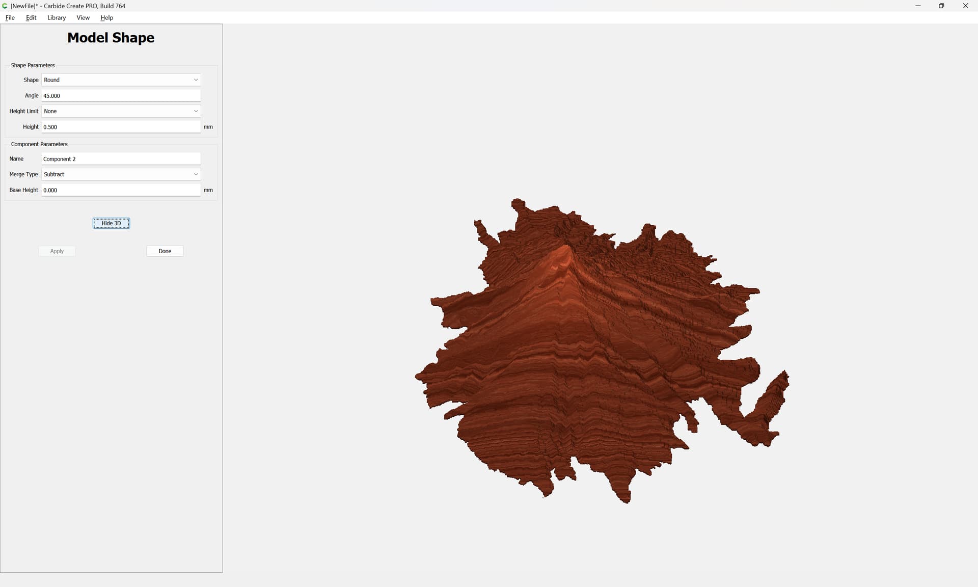
download relief map from where ever (I used 1m reliefs in the UK that are available from DEFRA)
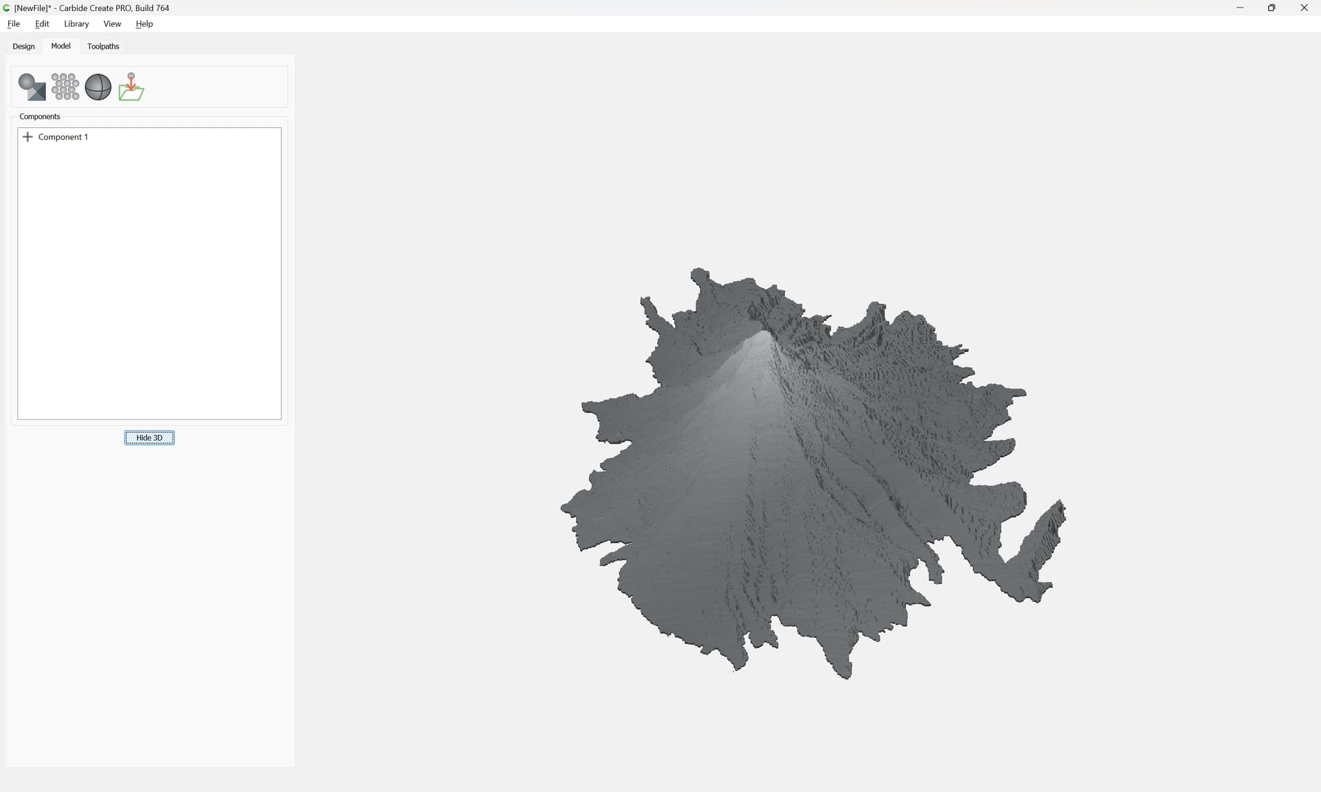
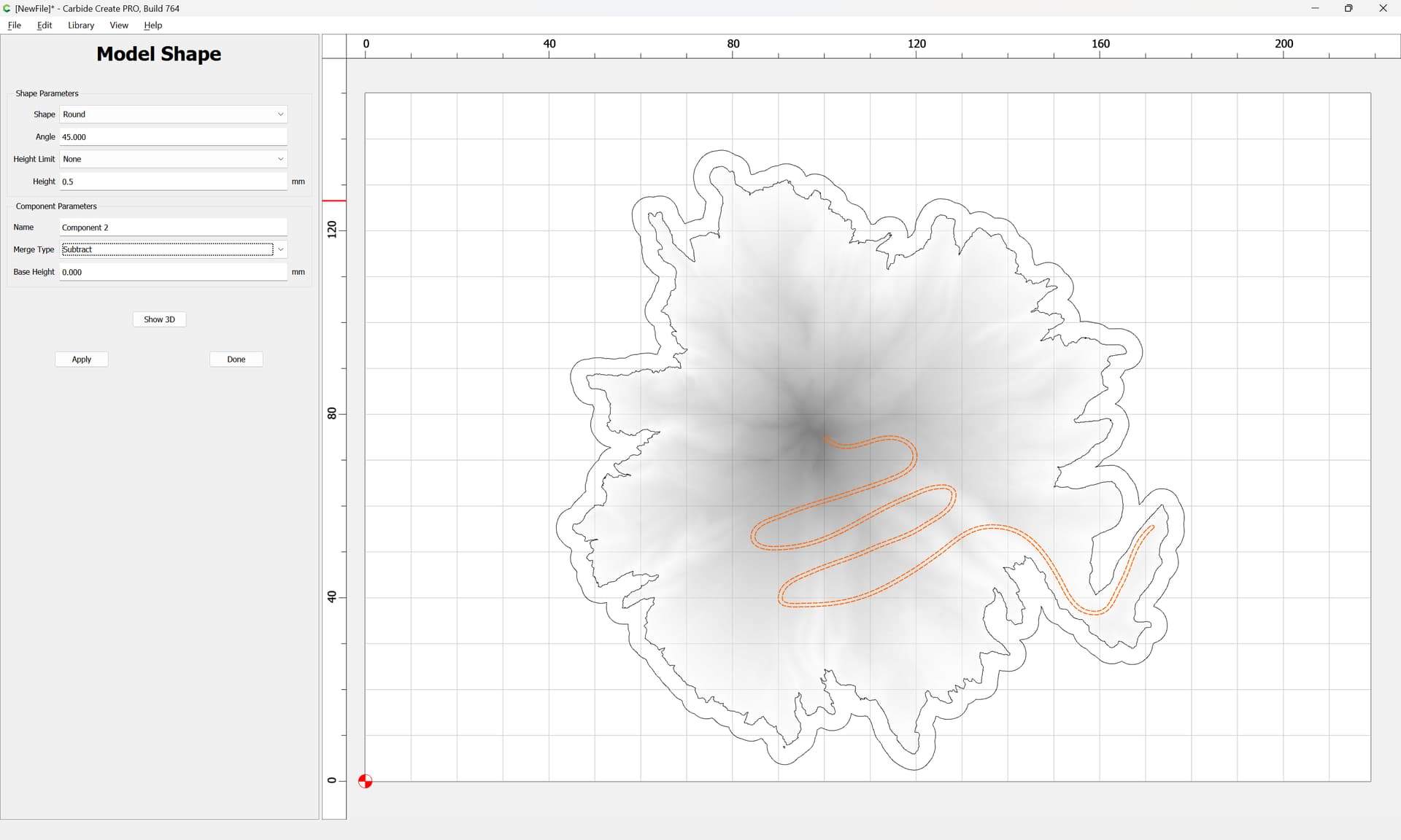
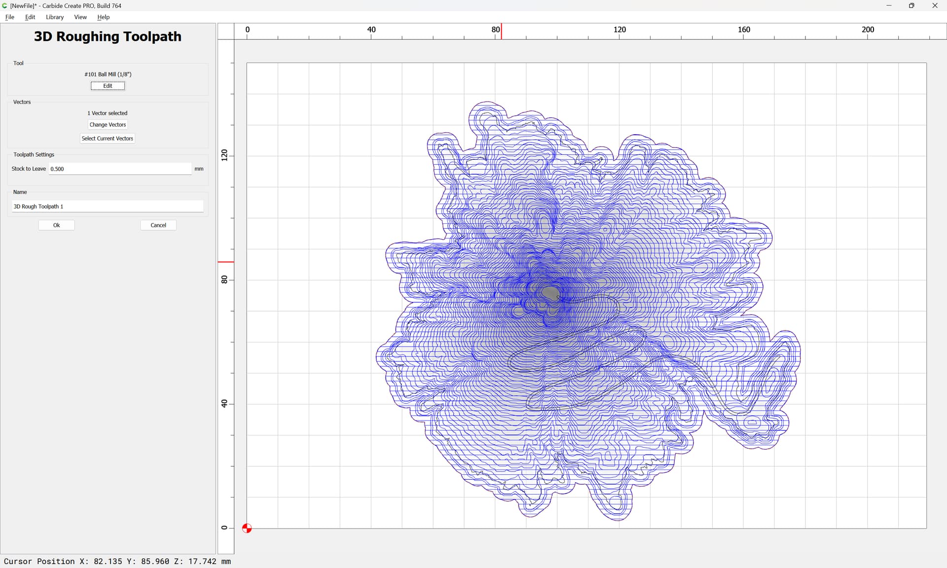
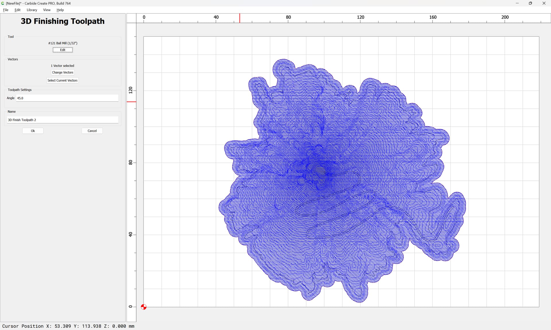
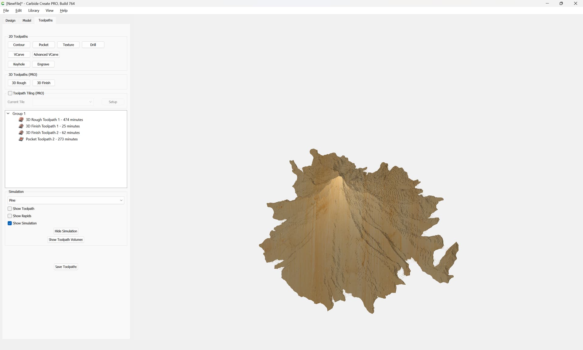
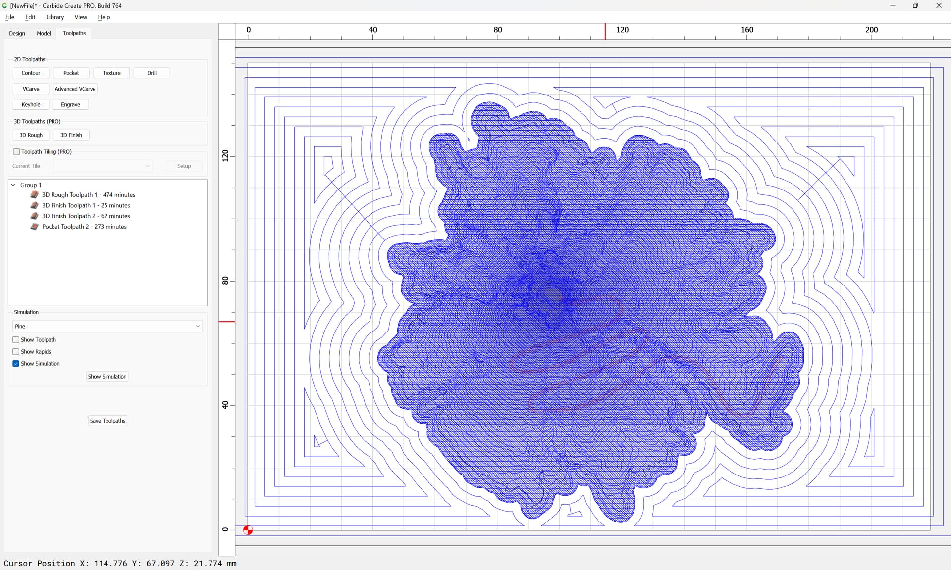
Use HeightField to create the terrain and output that as a .obj file and processed into a toolpath in VCarvePRO.
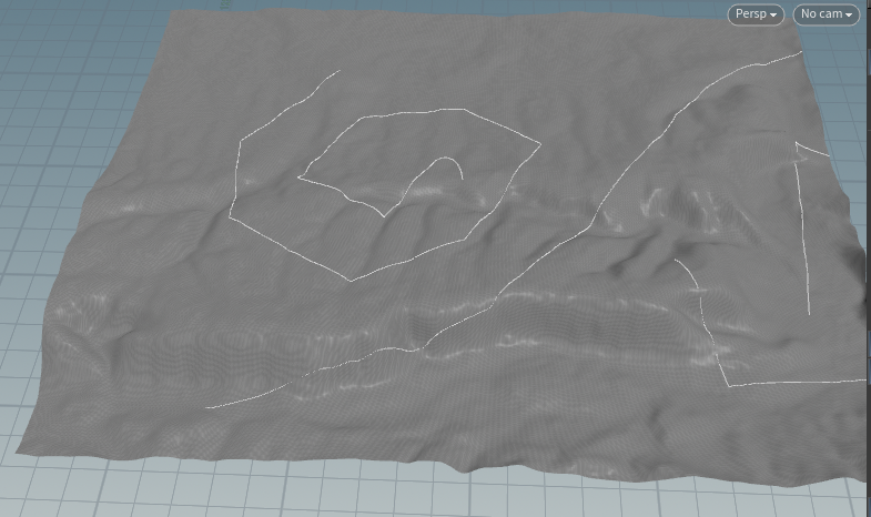
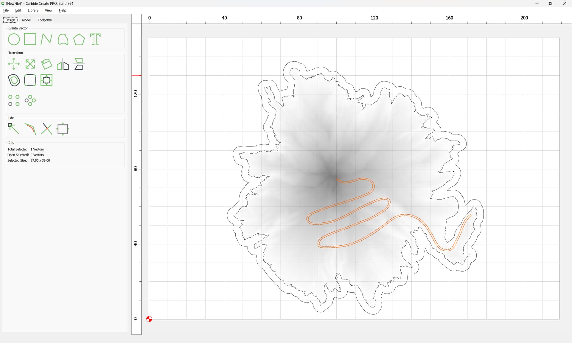
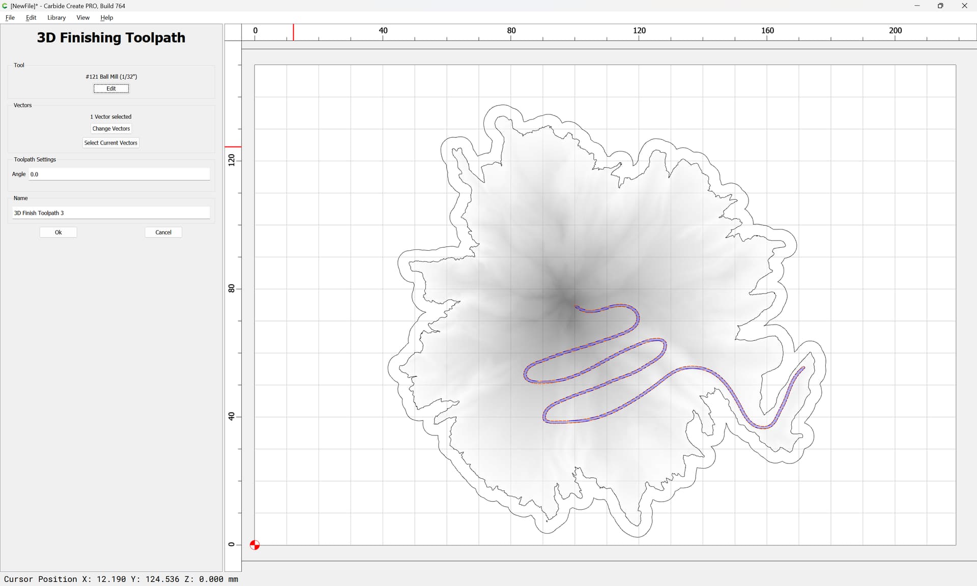
Use Ray to trace the paths to the 3d terrain (which can be curves from Open Street Map or hand drawn curves) → basically map the path to the ups and and downs of the terrain. (This is the hard bit that the original author must have developed their own code for)
Output the ray traced curves to a .poly file (list of points per path)
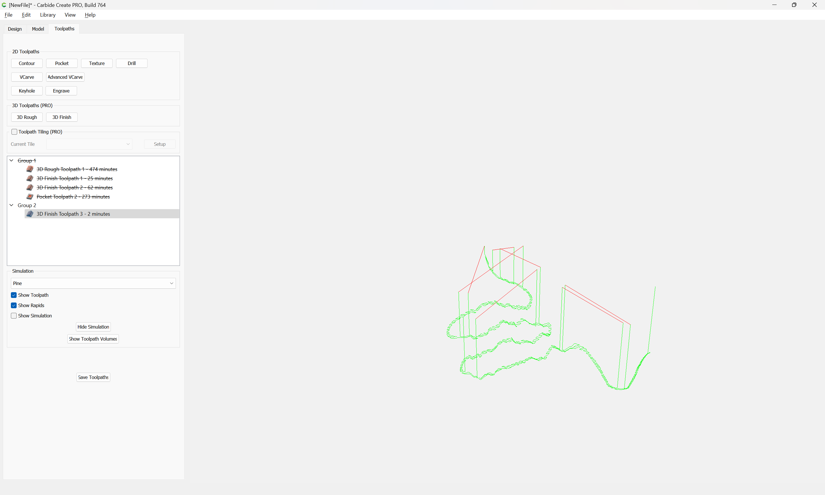
Process the x-y-z points using a small python program I cooked up (it was much easier to write the gcode than I feared) - basically stuck G1 in front of each x,y,z coordinate.
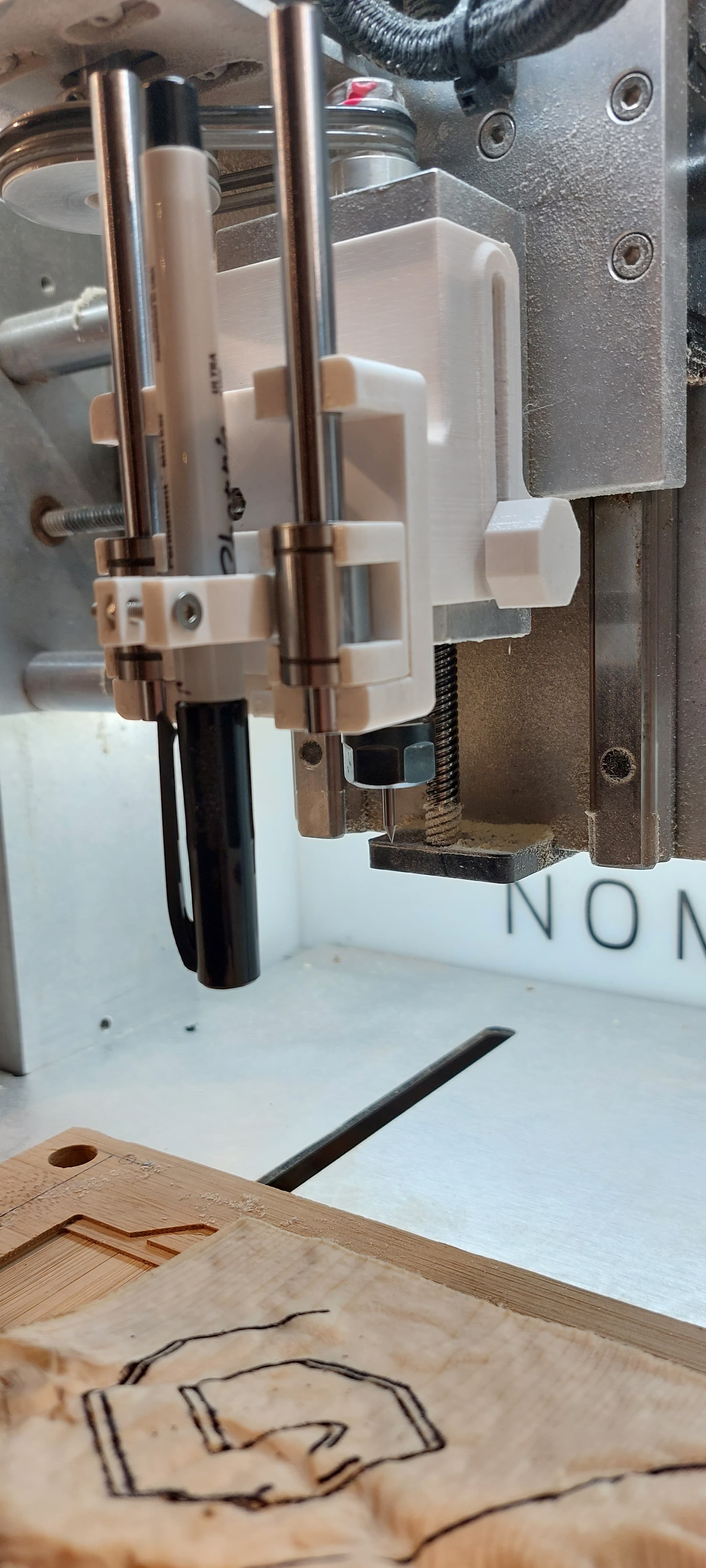
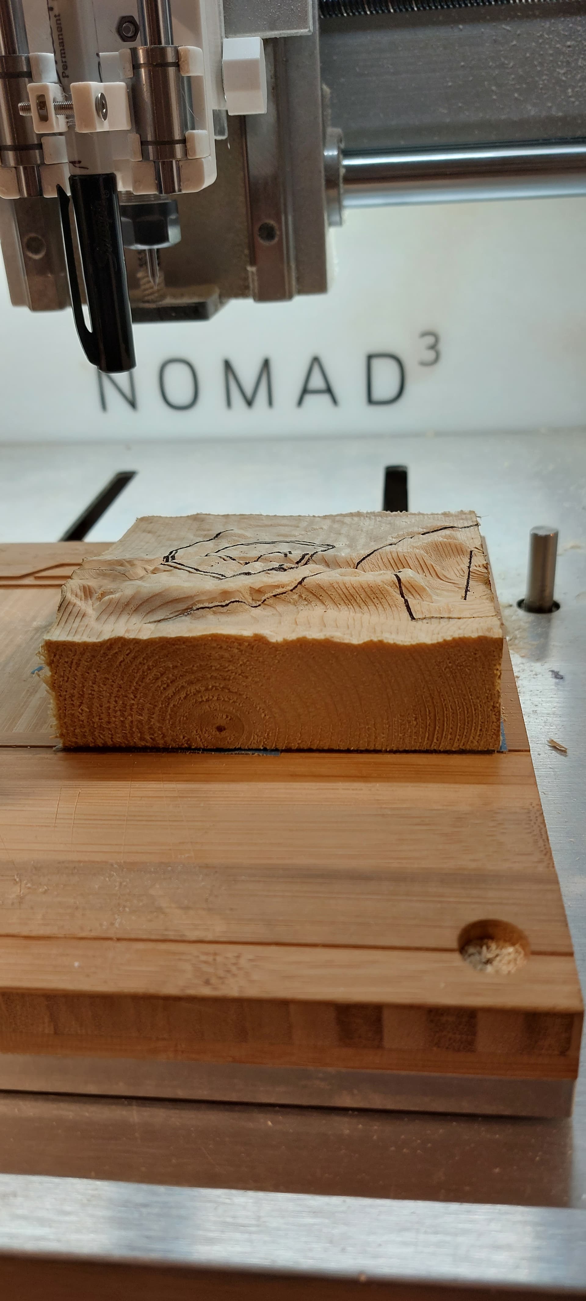
It is possible to both mill a groove for the path or use a pen attached to the spindle with a path offset as the pen isnt in the collet.
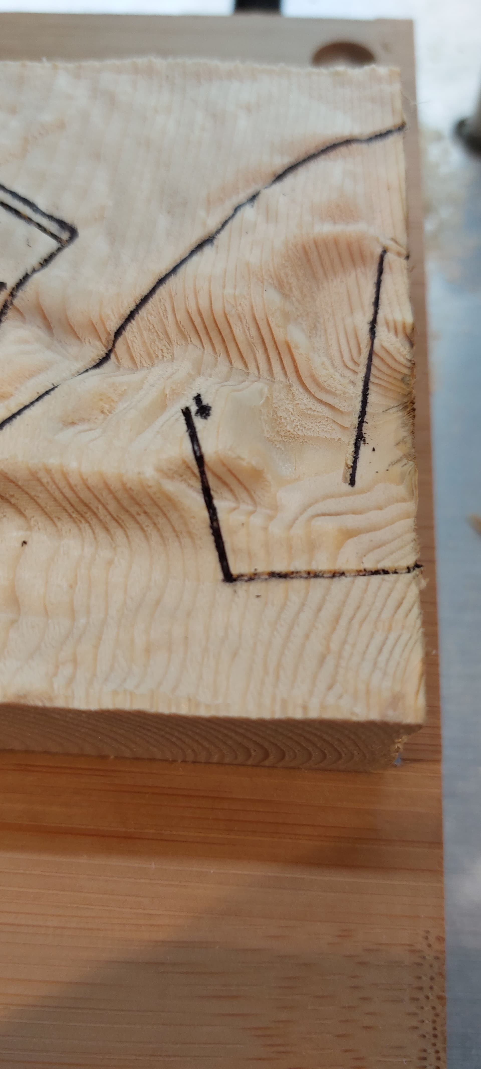
Attached are the raw test output in 100mm square pine. The double lines are where I had to calibrate the pen vs the v-bit in the spindle (in my case 50mm in Y and 1mm in X). I used the pen to follow the v-bit groove which is 0.5 mm deep. When I have some better peices of work I will post them,
I can provide more details if there is interest. It wasnt as difficult as I thought it would be so if you want to have a go at making your own version with whatever 3d package and program of your liking (it would also be possible to create the gcode of the xyz points with a text editor.
A thought: the approach is a lot like an autolevel program (which I also looked at to see if it would give me a short cut).
Just let me do 3D finishing passes on whatever, and then go back with an engraving bit and carve fine details (like trails) off a vector that follows a 3D height map without getting hacky about it.
If you are trying to draw or mill the ‘trails’ into the terrain, personally I would import a model into SolidWorks and draw the trail paths onto the top plane, and then extrude each one as a vertical surface (or widen them a bit, and extrude as a solid). Then grab an intersection of the terrain with the path, which would yield geometry which you could export and use for generating g-code that would engrave/mark on the ‘terrain’ that has been milled.
-Christian
Good idea. I dont use SolidWorks.
The challenge is (1) geographically aligning the 3d-relief and the paths and (2) beling able to mill the relief with a larger endmill than the paths.
Is SolidWorks similar to F360. I use F360 a lot but it struggles with largr mesh sizes.
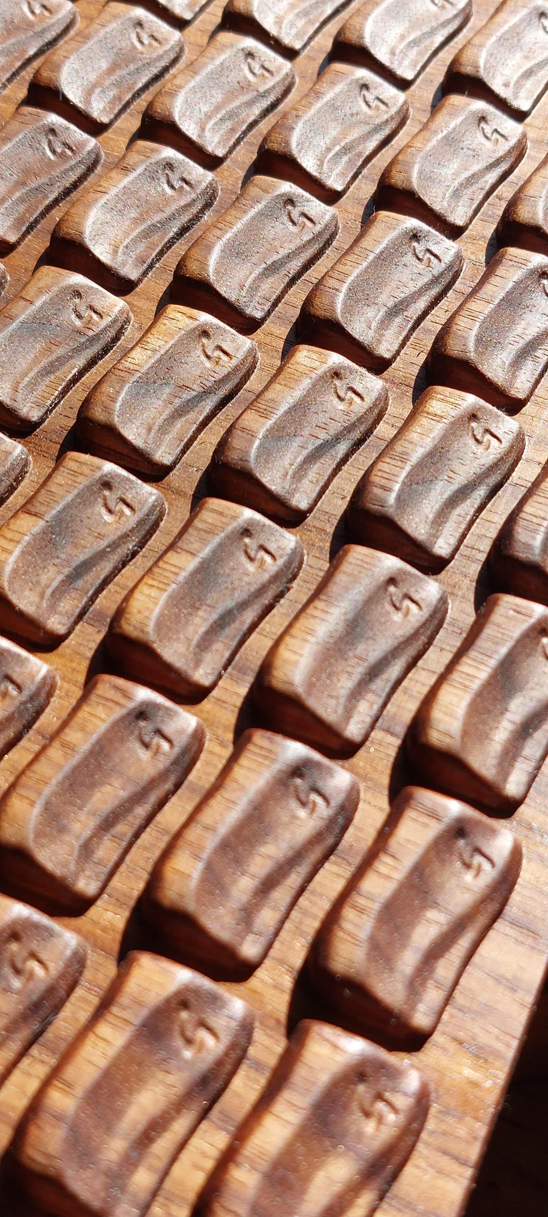
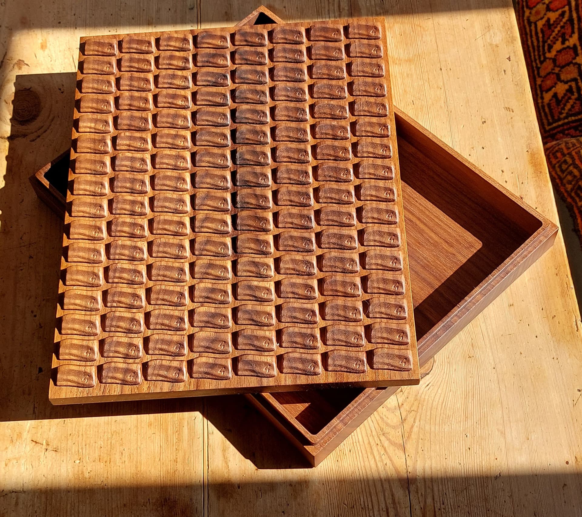
I have done similar with Houdini, again, (also possible in Blender) of drawing curves on a surface, extruding and then boolean the path into a 3d-relief as either a groove or a raised piece of geometry (although the raised geometry looked like worm trails). Below are examples of a letter G in a chocolate bar box. The downside is that i had to mill the whole piece with a bit small enough to get into the narrow groove of the letter G which made the milling process very slow, so i wanted to separate the grooving from the overall milling of the relief.
I also have plans to bring in KML files generated others of the areas they want treating in a particular way. These need to be geographically align to the relief. This is driving me, i believe, to doing much of the design in QGIS (using the same coordinate system as the raster files but not limited to DEM files from the space shuttle surveys which are only 30M resolution.)
I am intrigued by SolidWorks though, i’ve never given it a go before.
Some folks really like Solidworks — my son got a lot of use out of the Veteran’s license I had while he was in High School for his classes — even got my well-heeled brother-in-law to buy him a 3D Connexion Space Mouse for Christmas one year.
Instead of milling the terrain detail, would this be something a laser could engrave? Then you wouldn’t be limited by the width of the bit. I don’t know if programs like lightburn support 3D movements though. Perhaps you could set it up as a milling process, but have a diode laser on the router head that would take the place of the bit.
I’d love a laser but not at the moment. I think i’d still need to move the laser in z to maintain focus. If i can get this working then i might justify buying one. At the moment i’m stumbling around trying to knit rasters together - i happen to live between 4 raster images that are in coordinates different to Open Street Map and for the life of me getting things to line up is mare. Im learning more about GIS than is healthy.
I commend your GIS studying. I tried for a bit and didn’t get far. Lasers are definitely pricey, but I know there’s a few people here who have one on their cnc. It would be a nice proof of concept to test, before anyone else invested in one.
Good question: much more than the 10k advisory from F360. I believe in the range of 3 million, more than that and vcarvepro takes too long.
For the uk i have used the 50cm square DSM or 1m square DTM from DEFRA which are 5km x 5km tiffs at 32 bit float resolution. And like reading proper map books (vs satnav) i find the area i want cuts across 4 pages, in my case 4 raster tiffs. So I merge them to one, reproject to a reference system common to OpenStreetMap (so i can use there data and convert kml files from google earth) and then clip to the area i need.
I have just run a map of Mallorca that was 20m square resolution but still needed 4 file referenced.
I find modelling with a lower resolution proxy of the model efficient, then go hi res for the final model with smoothing to avoid faceting in the 3d relief.