More CC Pro fun

Hi folks,

Since I had fun 3D-carving stuff using CC Pro for the challenge dare last week, and since I had a second block of 3"x5" Renshape left, I tried something a bit different.

I started by generating a wavy surface in the first online plotter I found that happened to allow exporting the resut as an STL file:

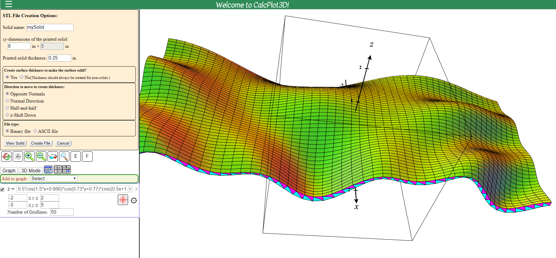
Then imported the STL in @fenrus’ online converter, and got this heightmap


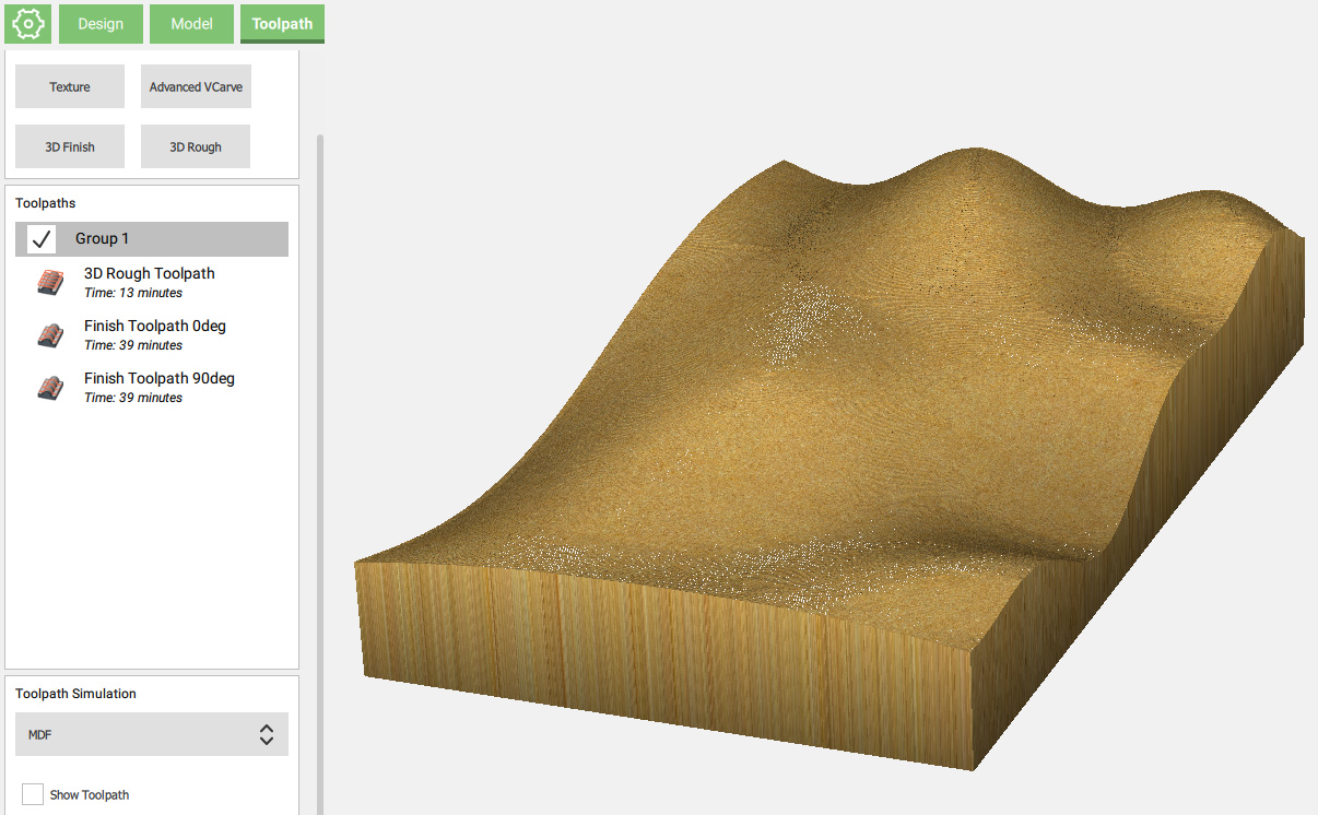
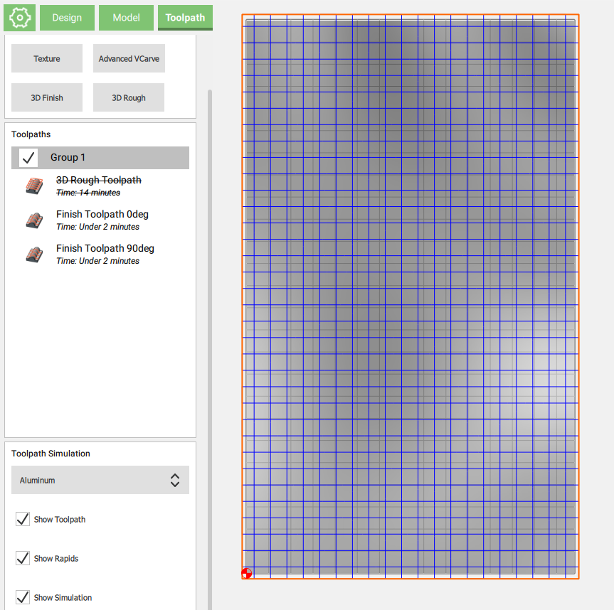
which I imported that in CC Pro,


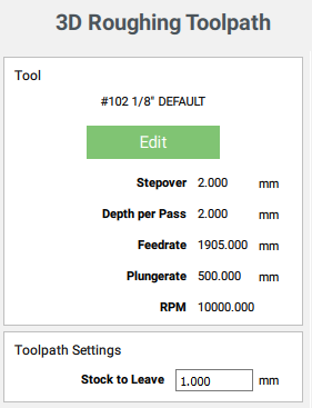
created a roughing toolpath with a 1/8" endmill,

image
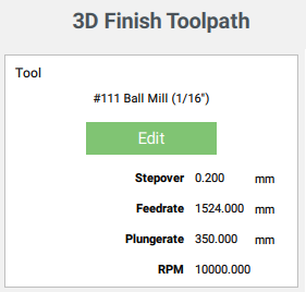
and two finishing passes (the second one 90deg from the first one)
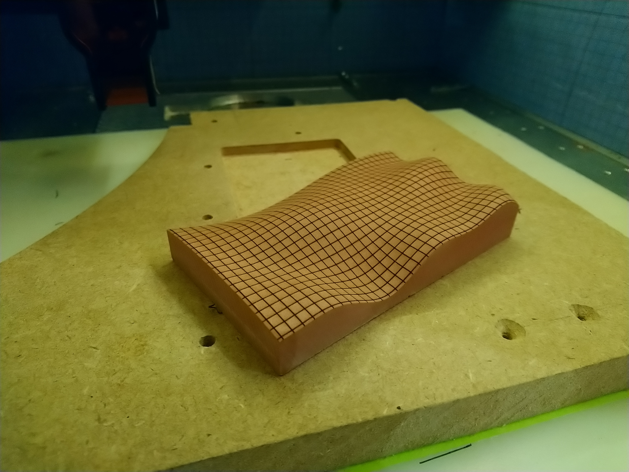
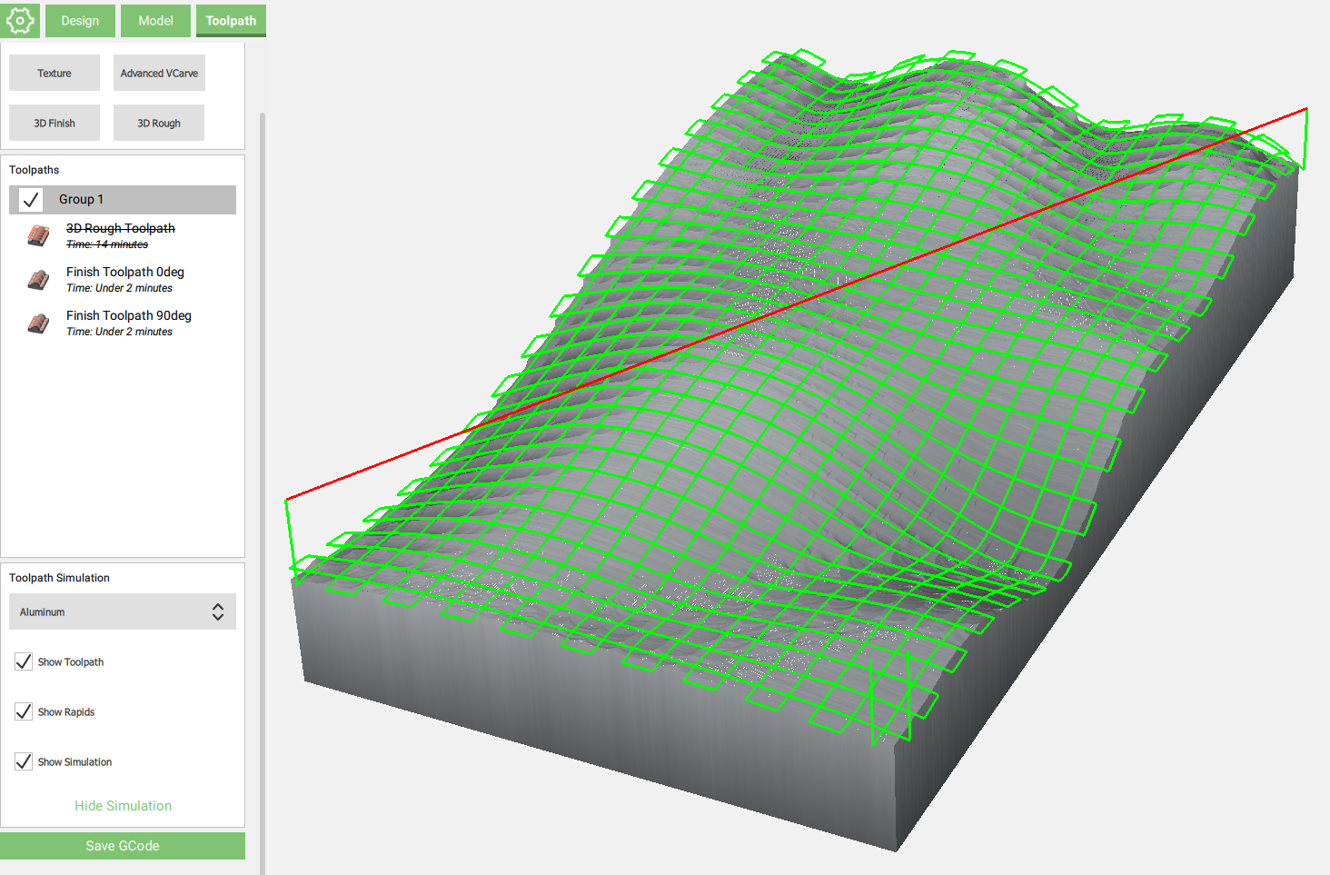
image
and ended up with:

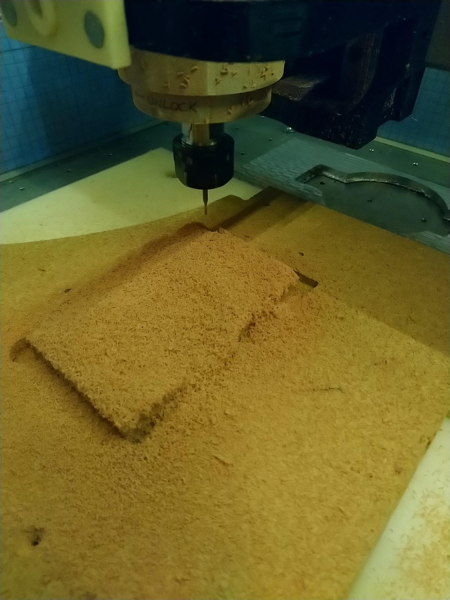
Roughing renshape was just as fun the second time around:


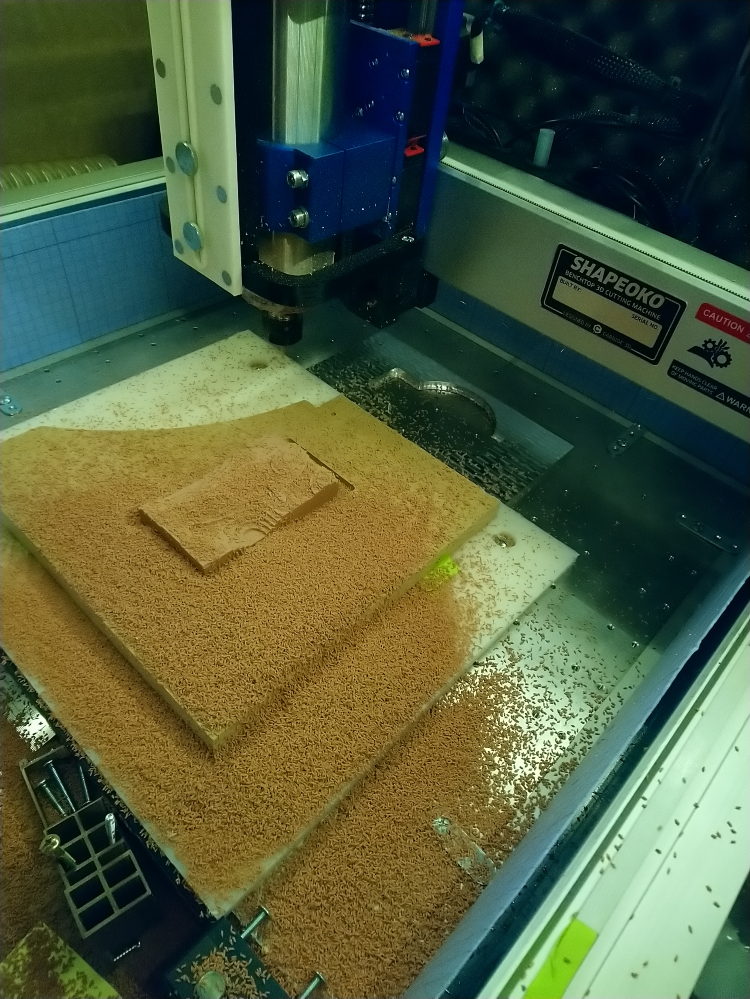
As cool as those tiny chips looked I cleaned up,

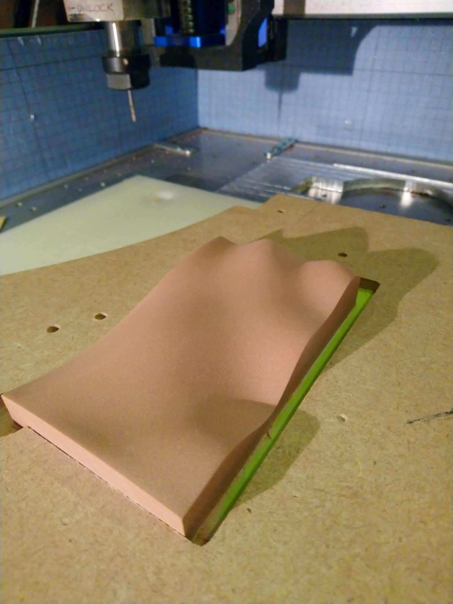
Only to bury the piece in much smaller chips during the finishing:

Finally I finished the piece with manual sanding (side note: I just LOVE renshape now):

So far so good, but the piece looked a bit “meh”, so figured I would lase a grid pattern onto the surface to make it pop.

NOW the interesting part: I realized I had only ever used my laser in 2D (X/Y) mode to engrave flat surfaces. And the focus depth of a laser is not so large, so I found myself scratching my head about how to proceed. I usually use LightBurn for lasering work, but it does not do 3D.

I remembered one of the most awesome threads on this forum, where @ClayJar explained his process to carve terrain relief, and then laser predefined paths onto that. I was about to go and check his PathTracer module to generate 3D trajectories for the laser, and then it hit me: what if I just used CC? the 3D surface is already in there, and I only needed a simple grid pattern.

So back in CC, I just reused my two finishing toolpaths, artificially set the stepover to 3.7mm (the grid step I found pleasing). By the way, it’s the first time ever I had to use a stepover larger than the endmill diameter :slight_smile:

I just made the rectangle slightly larger than needed, so that the laser would not stop/linger right at the edge of my stock.
And with the beauty of CC Pro, I got myself a sweet 3D-lasering toolpath!

After a couple of tests I determined that a combination of 500mm/min feerate and 50% laser intensity looked ok, so I programmed that feedrate in CC, and set the “RPM” to 12000, which happens to be 50% of my 24.000RPM GRBL setting, so that the PWM sent to the laser will be at 50%

image
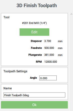
Note: I artificially changed the tool to “#201 Endmill (1/4”)", this is a trick to workaround a behavior (bug?) of CC Pro when using small endmills, discussed here, and the tool size is irrelevant anyway for laser work.

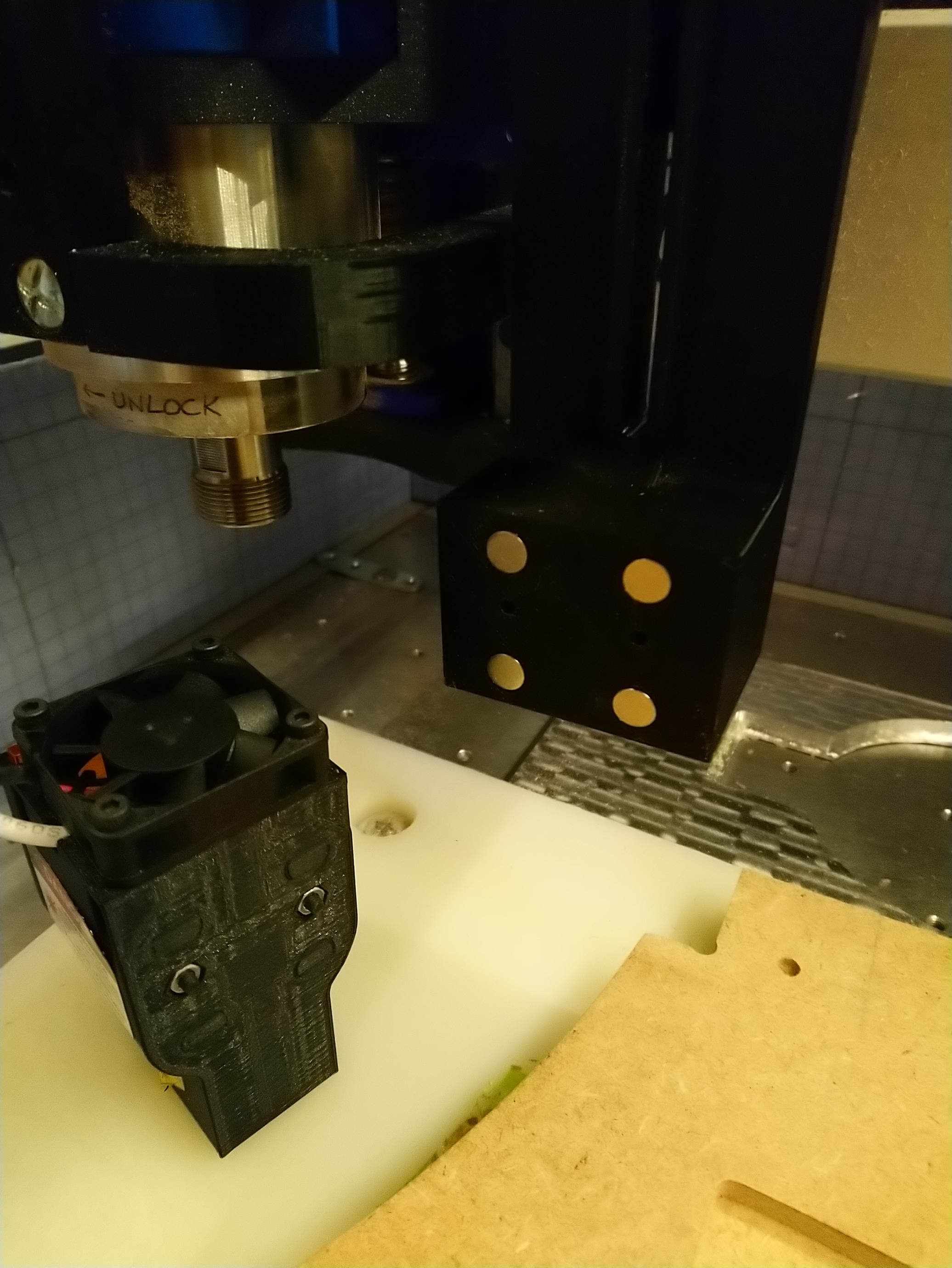
I had exactly one shot, so I triple-checked everything, took a deep breath, and zeroed the laser position:


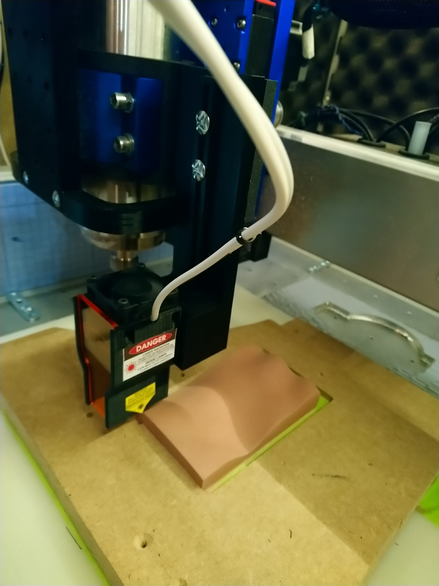
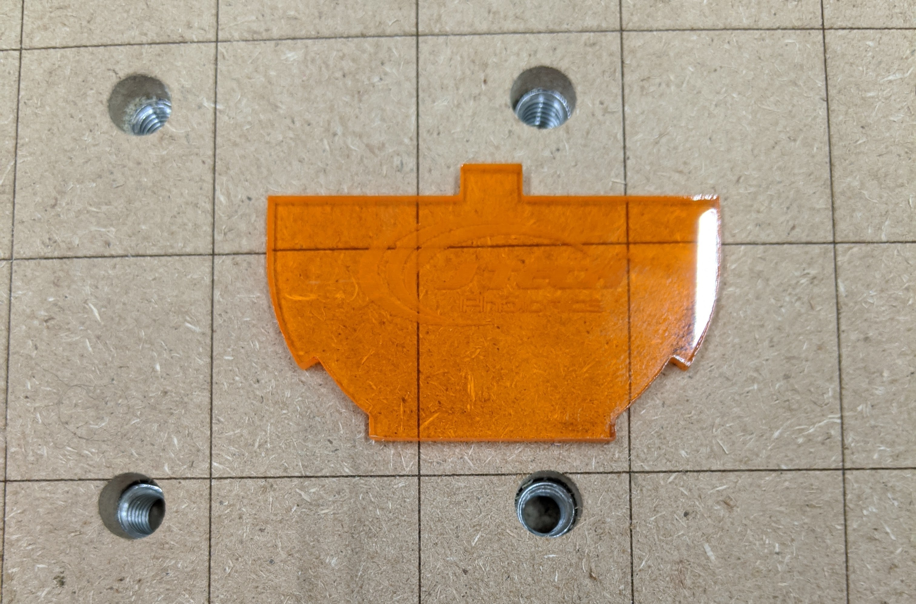
And was relieved to see that it went fine:

(I had my laser googles on in addition to the shroud, which I always do, but this time since the shroud would be higher up than usual, it made even more sense. SAFETY FIRST people)

Anyway, here’s the final piece. “It’s not much, but it’s honest work”, and I really liked being able to use CC to the full workflow, lasering included !

12 Likes

cool

this makes me want to buy one of those lasers that goes into the router (so no external setup) and then laster google maps road data on terrain …

3 Likes

I want to buy one too :wink:

out of curiosity, @Julien what kind of laser do you have?
Is it adaptable on a shapeoko?

I have the JTech laser kit, it’s easy to hook up to the Shapeoko. Expensive but has lots of safety features that mattered to me.

Are you happy with it? How much power does it have?

https://jtechphotonics.com/?product=spindle-mounted-laser-and-driver-kit this one just goes into the router … makes alignment easy

1 Like

I was wondering about 3D lasering, and how to accomplish that. I bought the 2.8watt JTech and although I haven’t used it too much, I find it to be something pretty nifty to have in the arsenal. I think you just wanted an excuse to use your 3D printed mount… I want to buy a Prusa printer now.

@Bwood34 : I got the 2.8W version. My rationale was:

  • it’s still somewhat affordable (the 4W and 7W were above my psychological price limit)
  • I was going to doing surface engraving only. Let’s be honest, if one wants to CUT things with a laser, one is better off buying a standalone 40W laser.
  • the native resolution seems to be optimal at 2.8W (higher power ones need a lens)

I’m quite happy with it, some people will say it’s crazy to spend north of 400$ for a laser module that is essentially less than 100$ of components, but I for one didn’t want to take any chances with a) my eyes and b) my house (I would hate to have “a chinesium laser module set his house on fire” as my epitaph), and what sold me on this model was the shroud (with magnetic mount, it snaps on and off in a second) and mostly the triple safety interlocks (on/off button + turnkey + external trigger that I wired to a switch on the outside of my enclosure). Anyway, this will sound like I work for JTech, but I just appreciate decent engineering.

@fenrus :interesting, this model did not exist (or I did not see it) when I bought one. But the big question is, what’s its max rated RPM ? :rofl:

@RoughDraft40: this time around it really WAS the other way around, and to tell you the full story, I found myself stuck with my previous fixed-Z-height laser mount. I felt really dumb not having anticipated that one day I would need to move the laser along Z…Hence the spindle-attached 3D-printed thing. Which could have turned into another smack-my-forehead moment, when I realized that of course I could not home the machine with it in place. Since I made it a snap-on thing, I dodged that bullet. Also, do give in to that Prusa attraction, it’s a great tool to have (and even you don’t, read about the story and continuous improvement approach of Prusa, it’s inspiring)

3 Likes

I’m curious about, setting zero. So, I’m assuming you set zero for your machining at bottom left corner with a touch plate then with the JTech, jogged to position and momentarily toggled the laser on to eyeball bottom left corner for alignment, is that correct?

Actually, since I didn’t know I would be using the laser at the beginning, my CC project (used both for milling and later for lasering) has zero setup on the top of the stock, bottom left corner.
When the time came to doing the laser, for X/Y yes I eyeballed it on the corner by toggling the laser on.

Interesting fact I learned: GRBL’s “laser mode” parameter ($32) not only prevents stopping the movement when the “spindle speed” changes (as it does in milling mode), it also has the built-in security feature that it will not allow the laser to be activated when the machine is not moving using a G1, G2, or G3 command. So I scratched my head for a bit trying to understand why I could not toggle the laser on and off when using M3/M5 commands before reading about that behavior. LightBurn has a “fire laser” toggle button that you can use, while being in laser mode, so i assume it must be sending fake G1 commands, or temporarily disabling laser mode behind the scenes, to do so. Anyway, my solution was to temporarily turn off laser mode by resetting $32 to 0, using M3S500 to turn on the laser at the minimum power where I could still see the laser dot, zeroing X/Y, and then setting $32 back to 1 before running the lasering toolpath (VERY important, otherwise the laser is not disabled during rapids…since I used CC to generate the toolpath, which is not aware that this was a laser job)

For Z, well I had no reference anymore since I had milled it away. I could have just set zero to “bottom” in CC for the lasering toolpath, but that turned out to be inconvenient too, because my piece was set in a pocket (MDF jig). Lazyness led me to just use a tape measure to bring the bottom of the laser shroud approximately 25mm above the bottom of the jig (i.e. my initial stock material thickness), and set zero there. It was not very important to be precise on Z on my case, I did not care much about how wide the laser marks would be.

That is such a cool idea and it solves the problem of firing, moving, firing, moving, firing, moving… I assume you have a couple macros in LightBurn to do that?

Also, you said you have the 2.8W JTech, right? And your shroud is magnetic? I have the 7W but my shroud is a clunky snap in thing that never wants to snap in on the first try. But that got me thinking and I looked at my order and it clearly says “Magnetic Shroud Upgrade: Yes” - so I need to get in touch with them - thanks for that!!

Stan

Edit- Just to be clear, the shroud is the orange plexi cover at the bottom of the laser, correct?

This time around I did not use LightBurn, but when I do I use simple macros to switch between CNC mode and laser mode (discussed here)

Yep, the shroud is the orange plexi cover, and it has magnets on the back. Mine also was not setting very easily in the original attachment thing that shipped with the laser (I could not use it anyway since it’s intended to be used with the stock router mount), I printed a custom bracket/arm with magnets, and it fits much better (enlarge the two holes slightly, and it should snap on much more easily)

Hmm… that is pretty interesting and helpful information to know. I use Lightburn as well, and I suppose I wouldn’t come across these speed bumps until trying to accomplish what you did, laser a 3D contour.

Do you have the OEM focal point, 1/8” from the bottom of the shroud? Did you do any calculations to whether the shroud would crash on an adjacent peak when it was engraving a valley?

@ctdodge I have the magnetic shroud upgrade from JTech. Definitely look into getting that since you ordered it; the magnetic setup is really easy and self locates. I have been taking off the whole JTech laser mount from the spindle mount (four set screws) when I don’t use it for longer spans to avoid potential unplanned crash tests though.

1 Like

Yes, I have the stock version that has the focal point 1/8" from the bottom of the shroud. And now you are asking the really interesting question, I did have a concern about the shroud hitting the peaks while lasering the valleys.

  • first I wondered if I could remove the shroud temporarily. But it did not look so easy to disassemble (while not breaking anything), and I would then have had to find another way to attach it, it was too much trouble. Also I’m paranoid when it comes to my eyes, so I like the shroud where it is.
  • I was WAY too lazy to do the math
  • I could have imported the surface in Fusion, modeled the shroud as a very large endmill the “diameter” of the shroud, and run the toolpath simulation there, but again too much effort.
  • so I just set my Z zero higher up than required, ran an air job to verify how much margin I had at the worst point (deepest valley near a high peak), saw that I had margin, set my zero to the right Z, rerun an air job with my hand on the emergency stop, and it went fine (barely) so I proceeded with the lasering.
1 Like

My laser mounts magnetically to the spindle mount and I do take it off when I’m using CNC mode. It’s the shroud itself


that isn’t magnetic

I have those same 2 macros, but I’m thinking I would do another for $32=0 and M3S500 to zero and then another for $32=1 (though that could just as easily be manual input)

1 Like

I wonder how it never bothered me more earlier when I was using LightBurn that the laser go off when moving while in manual “fire laser” mode. It can understand the safety concern behind that behavior, but now that I have noticed it, it’s irritating. Next time I use LightBurn I’ll probably make a set “Fire Laser” and “Stop Laser” macros indeed, good idea.

Actually, now that I think about it, creating macros would bring back some of the safety that we would lose by circumventing LightBurn’s defautl behavior: having the macro do the “M3S500” line for us would prevent one from mistakenly typing a high RPM number in the console, and having the laser go off at full power.

Oh I see. Getting into a little bit of semantics, but in my opinion, the shroud is the whole encasement of the laser and fan. The plexiglass being part of the shroud. By this definition of what the shroud is, you would have the magnetic shroud upgrade and that is what i have too. I’ve never attempted to pull the orange plexiglass off before.

When you guys are talking about macros, I get the gist of how you would create them in Lightburn as buttons that automatically generate a line of coded command to be sent to the grbl board(?), but when you create macros outside of Lightburn how is that accomplished, are you guys using a different gcode sender that has “buttons” you can program? I’m quite naive when it comes to understanding coding.

I just tried those macros with my laser and it doesn’t work. I set $32=0 then M3S6 (since my max “speed” is 255) and the laser comes on very low, but as soon as I jog it the laser goes off. I also tried it with $32=1 just for hahas and it does the same thing

You may be right - I just looked at the Jtech site and they have the “magnetic shroud upgrade” that contains the “shroud” which is the case and the “laser shield” which I’m assuming is the orange plastic part. But the kist they show does have a full sized “shield” that goes from top of shroud o bottom and slides in some slots, whereas mine is what you see above. I take the shield off when I’m setting zero so I can see the pencil marks

Ha. There must be a hardcoded behavior in LightBurn to send “M5” as soon as one jogs around, or something like that, to prevent us sneaky users from perpetrating mischief.

After spending a couple of minutes on the LightBurn forum, it’s quite clear that:

  • this behavior is done on purpose for safety
  • and mostly applies to people controlling powerful C02 lasers (which I guess is 99% of LightBurn user base).

I don’t have a standalone laser and never had one, but it seems like they usually have a “test/positioning” mode that does just what we would like, but at the laser level, so those users wouldn’t care.

There does not seem to be any complaints from diode laser users about the behavior of the “fire laser” button, so either everyone got used to that annoying workflow, or there is a configuration trick somewhere.