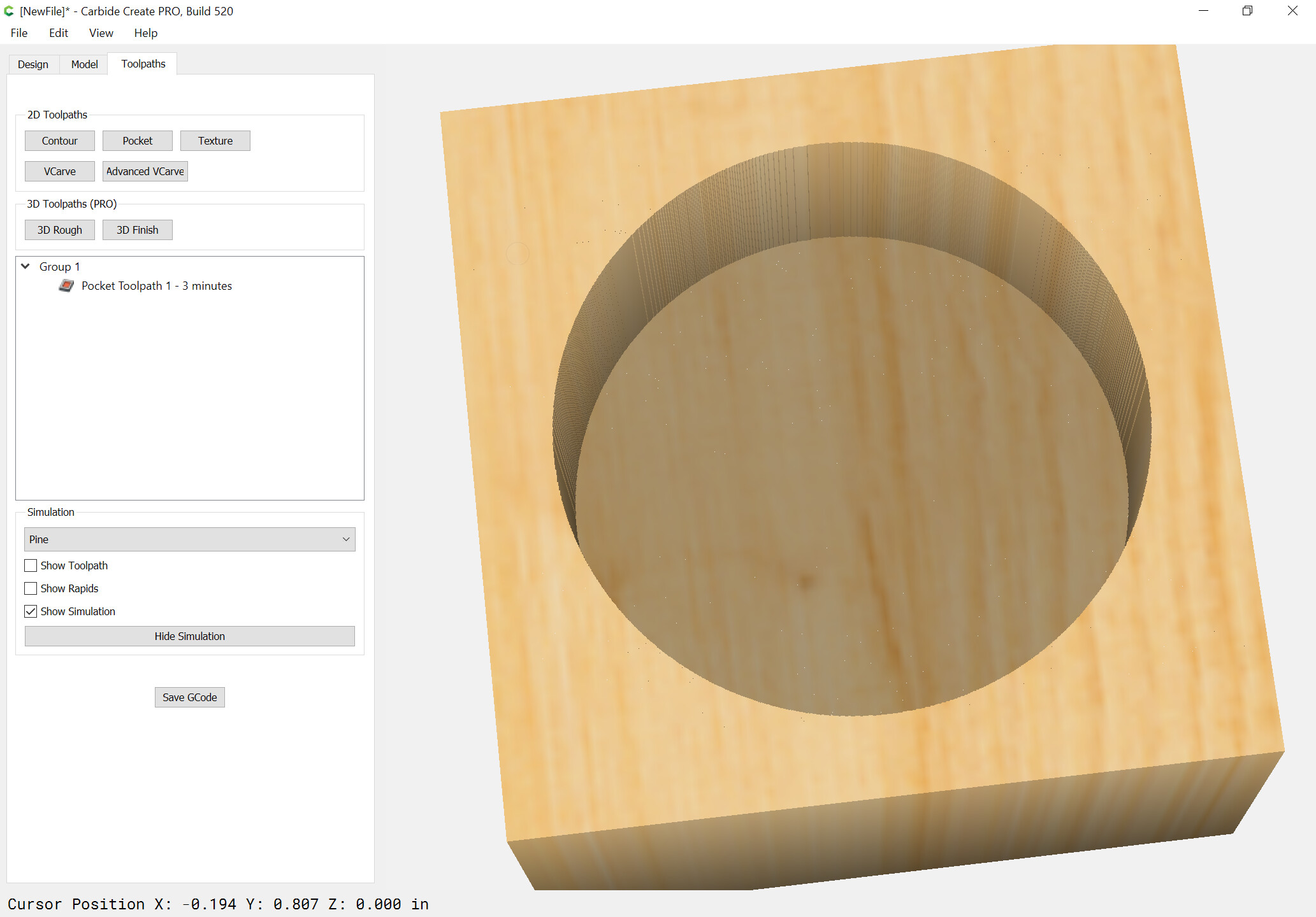
arbitrary shapes which do not have any acute points which cannot be cut by a round endmill — obtuse points can be — consider a star shape, the points of the star cannot be cut w/ a round endmill, but the internal angles can be, since the endmill moves around the angle.
forms defined by the surface geometry and the angle of the V endmill used for V carving:
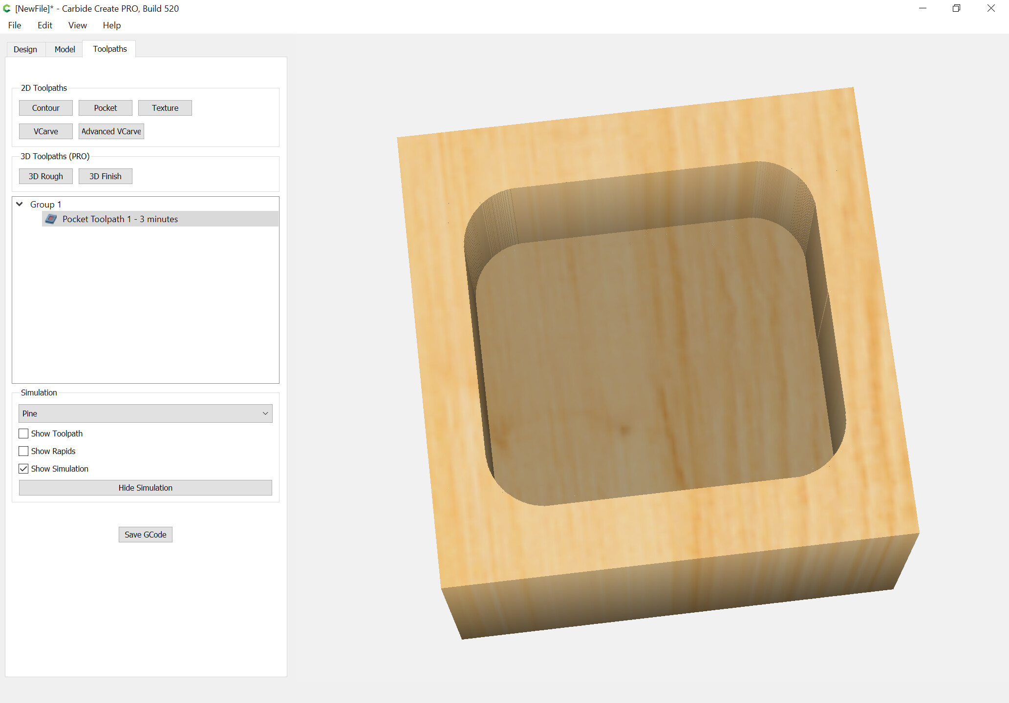
The pockets above may easily have rounded bottoms added by insetting the geometry as needed to allow for cutting the bottom of the perimeter w/ a ball-nosed endmill as seen in:
Cutting past the stock along two edges will allow flat bottom geometry w/ square edges as is needed for fingerjoints as is seen in:
(requiring a fixture for holding stock vertically)
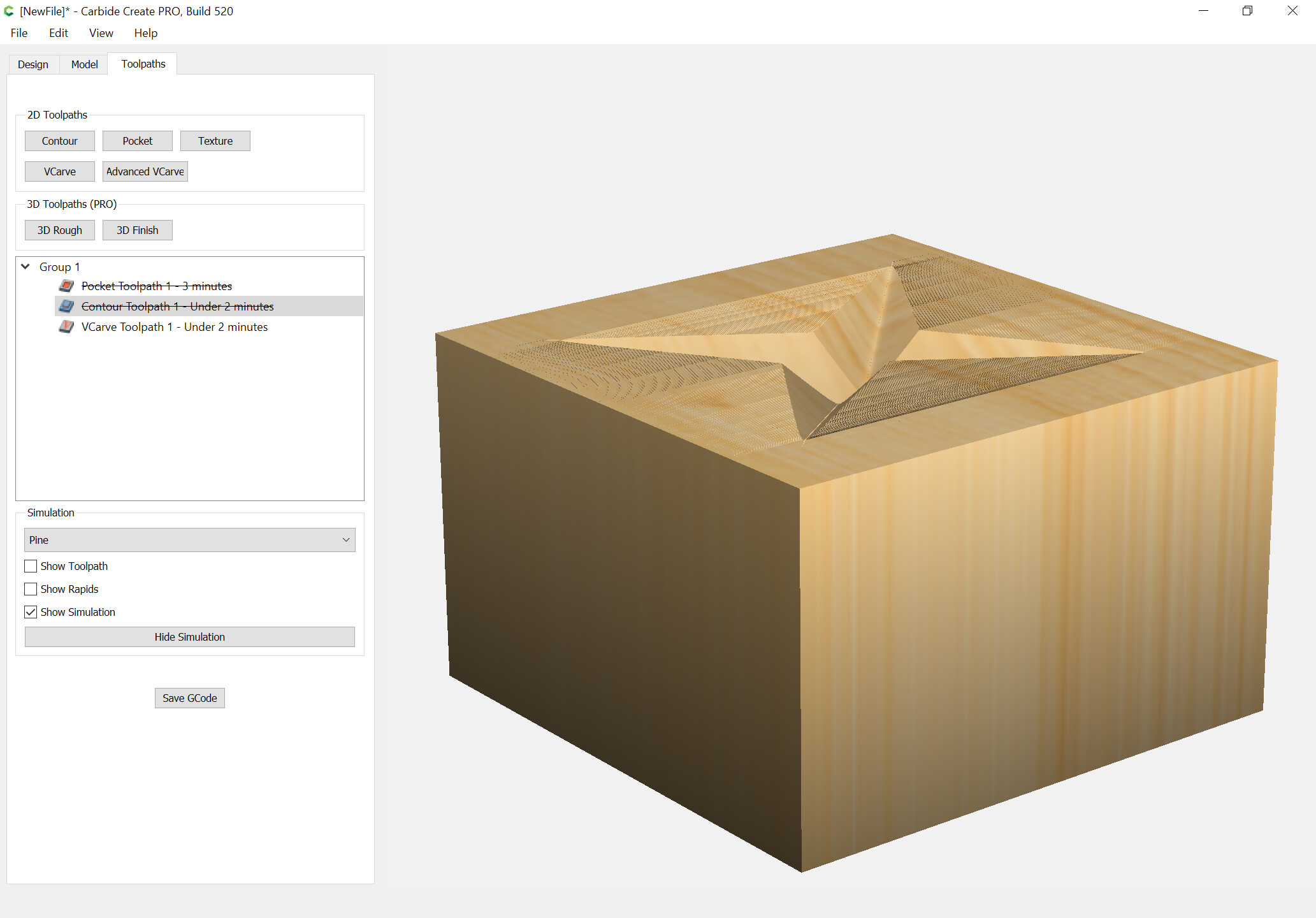
Advanced V carving allows for flat bottomed pockets w/ angled edges which match those of the selected V endmill w/ a bit of additional rounding.
Other geometries either require special tooling and forgoing a 3D preview or 3D modeling them, e.g.,
One thing worth noting — as noted above, it is pretty straight-forward to cut angled sides which match, and if the desired depth is greater than the endmill can cut, then it is simply a matter of stacking nested geometry to cut the angle as noted at:
Geometries which are notably difficult to descibe/model/cut are those which involve an angle which exceeds that which can be easily described in a V carve.
Unfortunately, there doesn’t seem to exist a CAM tool which allows one to specify a path or closed region and have it cut at one depth at the beginning point, and to continuously change along the length of the cut to a different depth at the ending point.
Similarly, it would be very handy to be able to select a region and have the bottom cut along the angle described by two different depths.
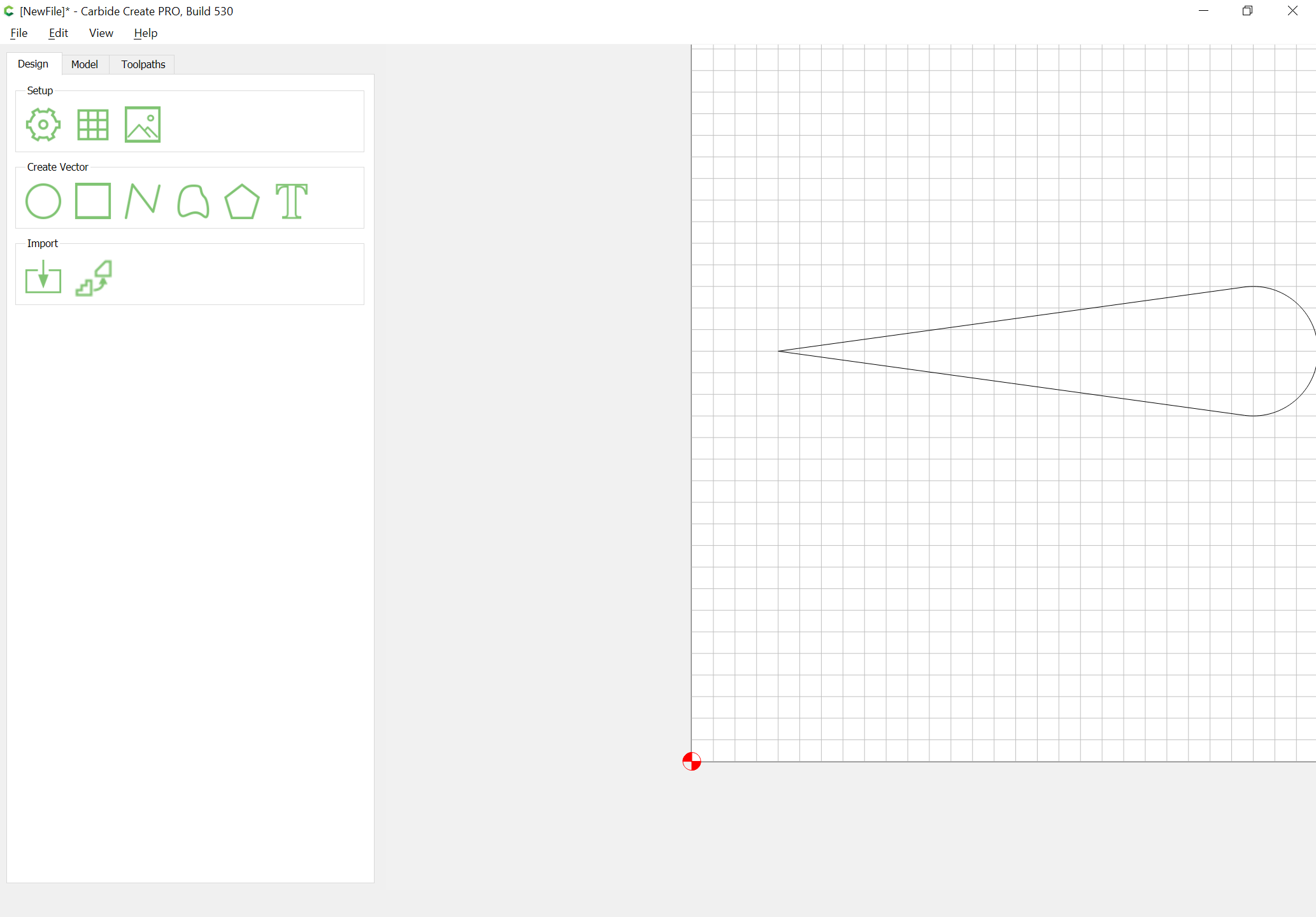
Came up w/ a work-around for cutting along an arbitrary angle w/ a given tool:
define a V endmill w/ a suitably acute taper and assign it w/ the number of the tool which you wish to use
draw an ice cream cone shape which is as long from tip to center as one wishes to cut and where the circle part is wide enough to cause the V endmill to cut as deeply as desired using a V carving toolpath:
Making the angled cut is complicated by there not being a way to represent it — the natural way would be a line fill option which blends along its length, but that’s not supported in the SVG format AFAICT:
I believe Fractal Design Painter had an option for this, and I suppose one could do it w/in the granularity of the tint percentages using a programmatic tool such as MetaPost, but there’s no easy way to represent something as simple as:
G0 X0 Y0 Z1
G1 X1 Y1 Z0
Where the origin is white and the endpoint is black and the line continually darkens as it descends.