And now for something a bit different — going to work out a miter box here…
We start by doing a bit of research on the basic concepts:
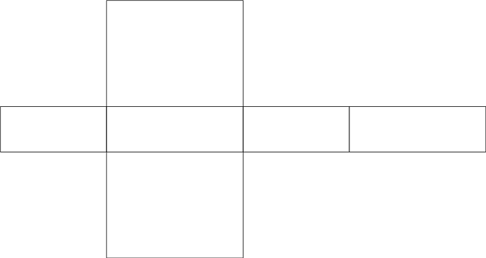
and work up some drawings / sketches and note some observations / theorizing:
- needs a 90 degree endmill for square/rectangular boxes
- should be possible to do hexagonal boxes using 60 degree endmills
- check and see what other commonly available V endmills might allow for useful shapes
Fortunately, the math is pretty easy for square / rectangular boxes and a 90 degree endmill — you just need a V carve which is twice as wide as your stock thickness to reach all the way to the bottom (which you don’t quite want to do if you want continuous grain — a radiused endmill may work well for this).
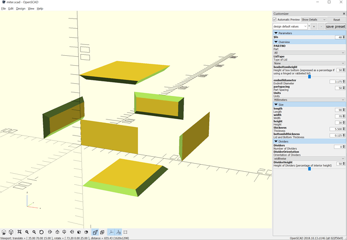
Consider a box which is 70mm wide, 90mm long, and 30mm tall made out of 5.5mm thick material:
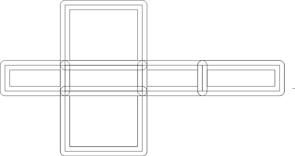
We would simply need to outline all the lines and then cut the outlines as a V carve:
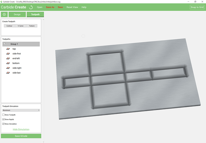
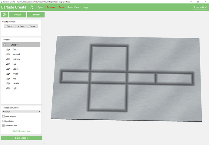
Which when exported to an SVG, imported into Carbide Create, and assigned V carving toolpaths previews as:
(after setting the stock thickness to 6.5mm, so some adjustment of the zeroing and material thickness seems in order)
EDIT: However, if one zooms in, the corners/overlapping regions are cut more deeply, making this unsuitable for this usage.
Filed a bug report.
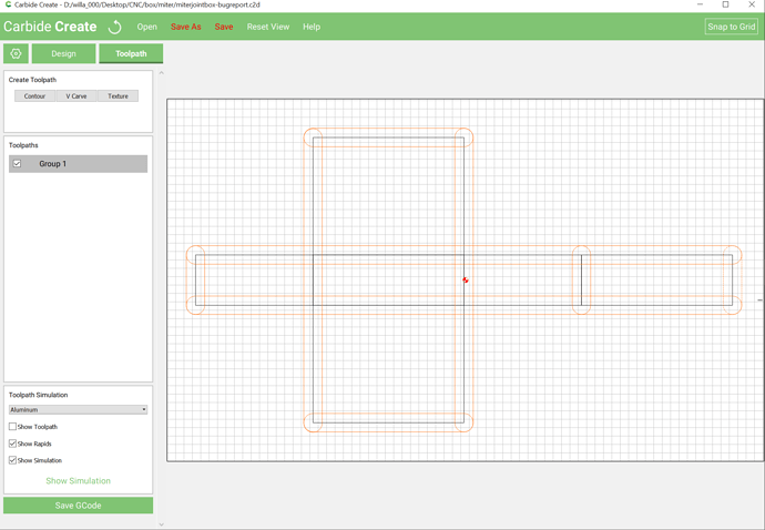
Instead, if one uses closed regions to define things one gets the expected depth, so it’s simply a matter of drawing in 9 suitably placed / sized rectangles with rounded ends:
which previews as:
Attached: miterjointbox_nine.c2d (34.6 KB)
EDIT: Note that since the above, was written, Carbide Create has been updated to allow a V tool to be previewed using a “No Offset” Contour toolpath.
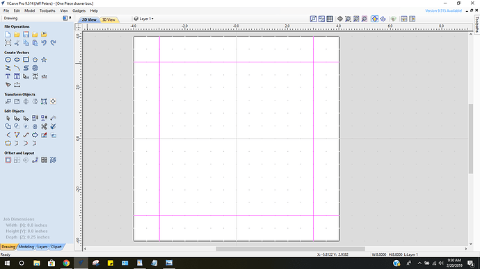
When I do my mitered box’s I use just 4 lines. 2 vertical and 2 horizontal
these lines extend past my the width and height of my material .
They are setup as the center of the inside of the box. The material is size is the width and length of the box center want plus the height of the sides V bit size…1/2" for 1/4" 3/4 for 1/2" 1 1/4" for 3/4 "
Tool path is run using the proper size vbit for the material thickness
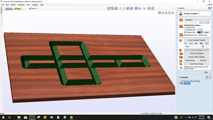
Select the lines and do a pocket tool path set to just a few thousands less of the thickness of your material
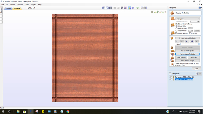
Here you see the toolpath. Also you see 4 square corners. Those get cut off with a drywall knife.
Put glue in all the v groves and then proceed in folding up the 4 side to complete the box.
Jeff peters
Very cool — I’ll have to work that aspect in as well.
Have you ever made a nested pair where the bottom nests onto the lid? What sort of clearance do you find that needs?
I have not tried to add a lid but I am sure going to try doing that…
On your simulation It does not appear that the box is cut out of the wood.
Is that correct.
Do you always work in MM. Not sure
Jeff
I believe that the V angle/depth is just enough to cut through, but that the cut is too fine / small for the preview to show. As inferred above, I did find a bug in Carbide Create though where it cuts much too deeply on the original sort of toolpaths shown.
I switch back and forth between Imperial and metric — whichever is more convenient. I’ve considered switching to metric, but haven’t since:
- the last time I priced it out, a metric version of my favourite (four-fold, brass-bound, boxwood) rule was ~$400
- the inability to evenly divide by thirds, sixths, and twelvths into nice even integers which Imperial affords (I’ll haul out a (PostScript) point/Pica rule so as to have 1/72nd of an inch if need be) when using metric drives me nuts — reminds me too much of working with folks in Europe at work on ad campaigns where the width of (say) a 2-column ad doesn’t equal column width x 2 + gutter width
That’s one of the major failings of the interface in OpensCAD right now — it’s not possible to programmatically update the dimensions when the units are changed. I’m looking into using a front-end programmed in LiveCode or something else which would properly handle that.
