This is a difficult shape to draw in Carbide Create since one needs outside rounding (easy) and internal rounding (difficult). Having a program do the math reduces this to just specifying a couple of parameters:
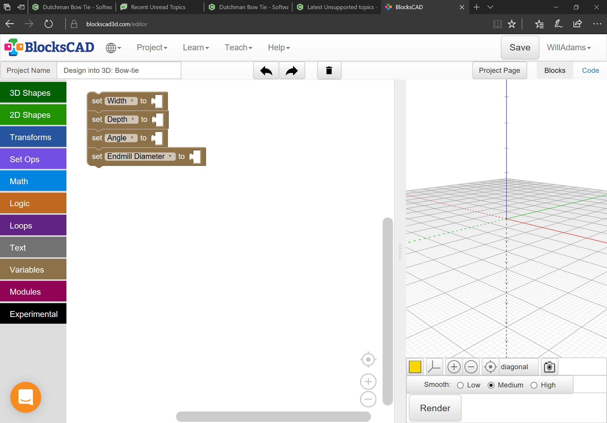
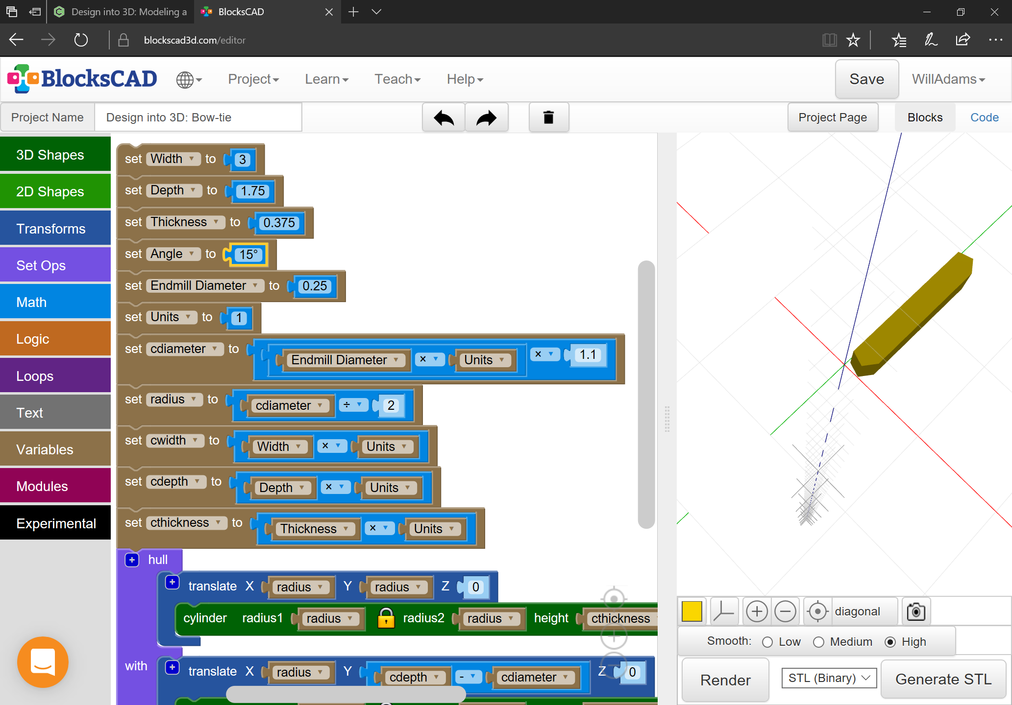
With the variables specified, we add support for units and the attendant calculations and begin placing things:
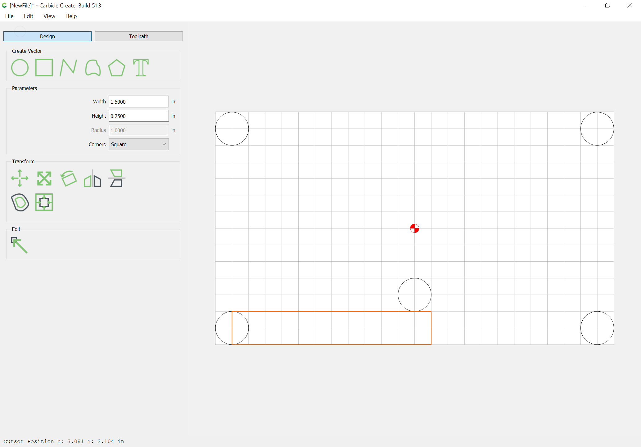
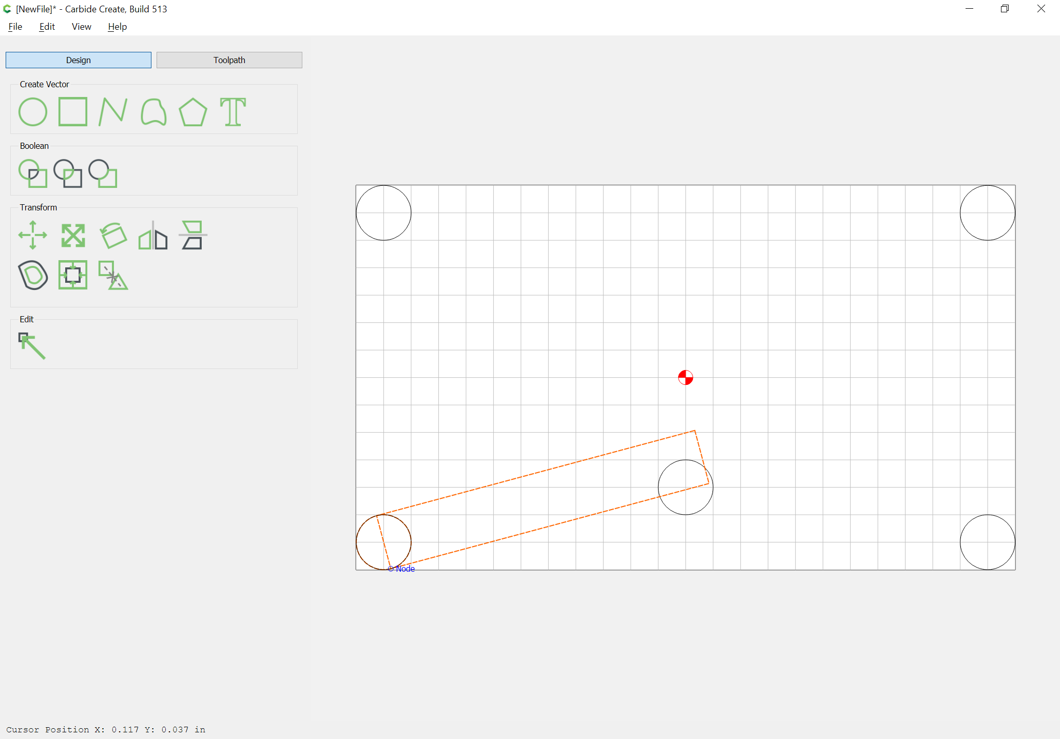
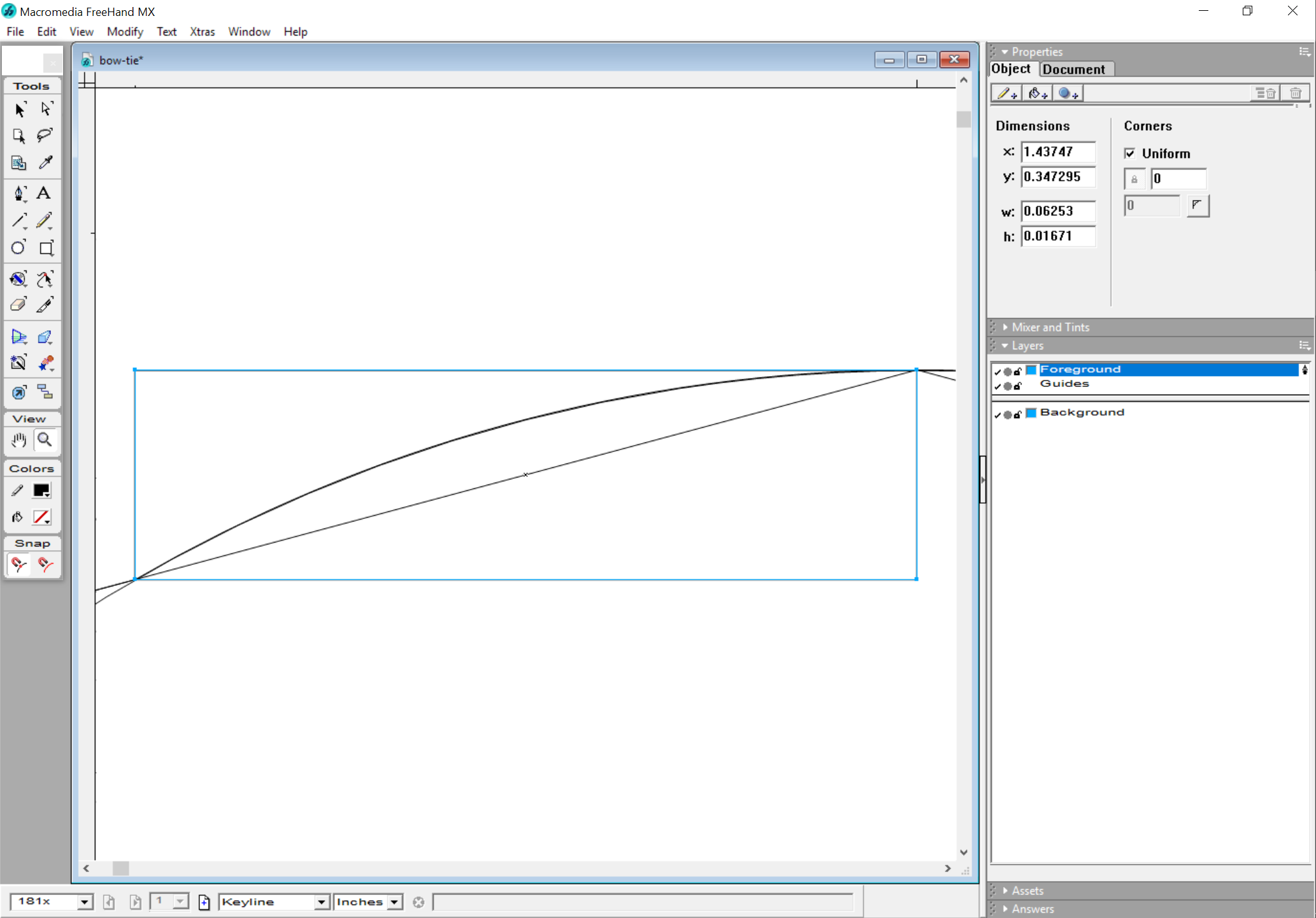
As a check on this, drawing things up in parallel in Carbide Create will help us to see what is involved:
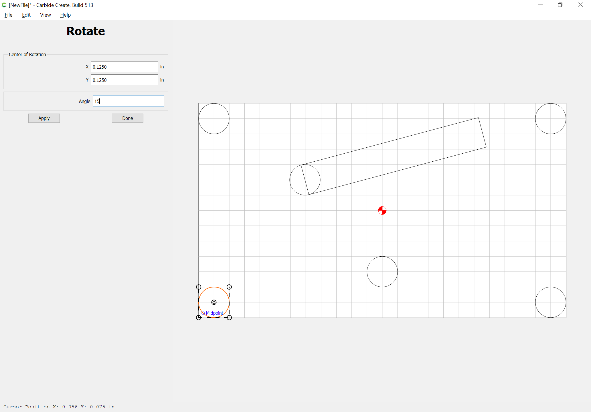
Note that the circle and rectangle need to be rotated as a unit, and a copy of the circle rotated in place as well so as to allow for snapping:
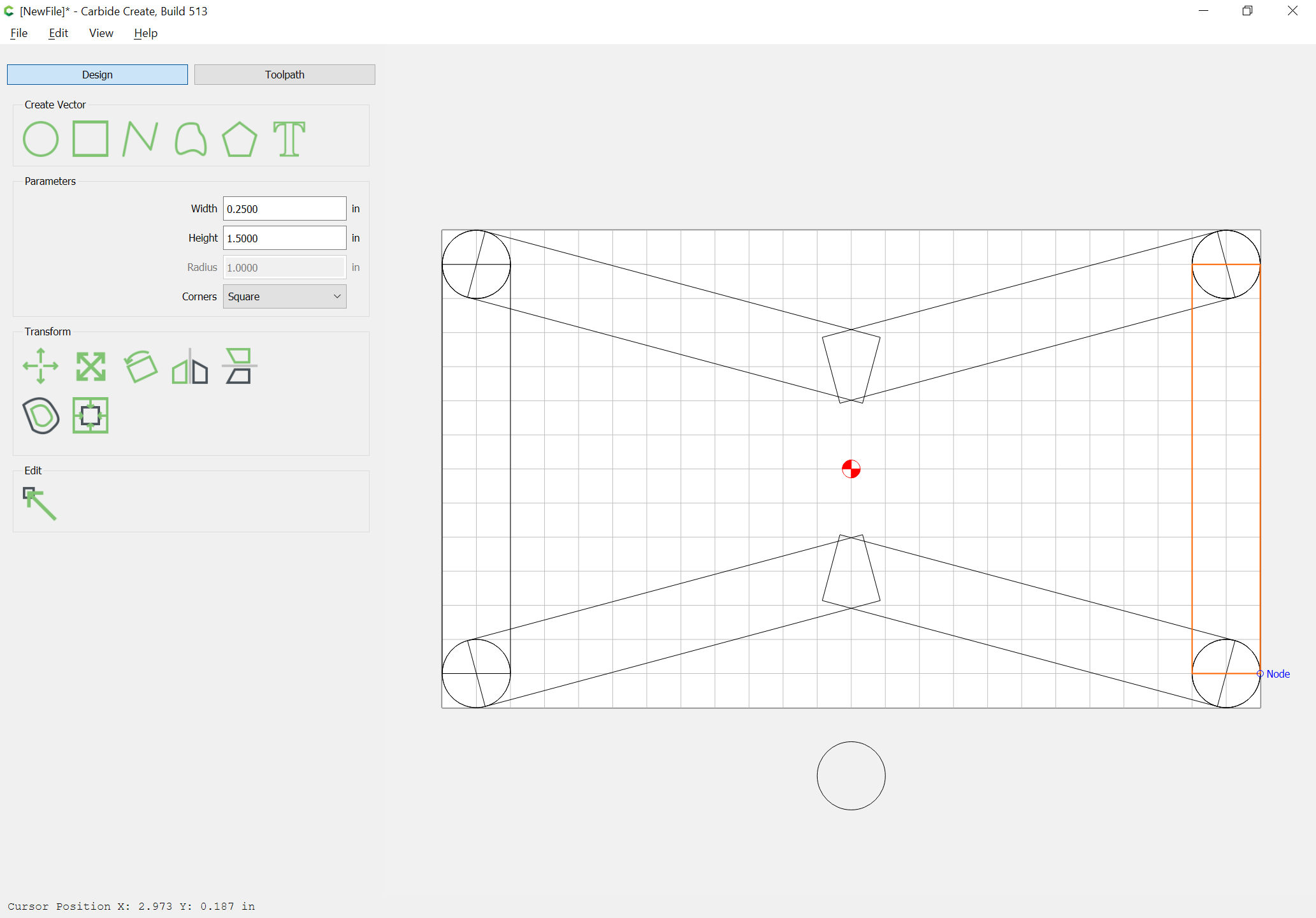
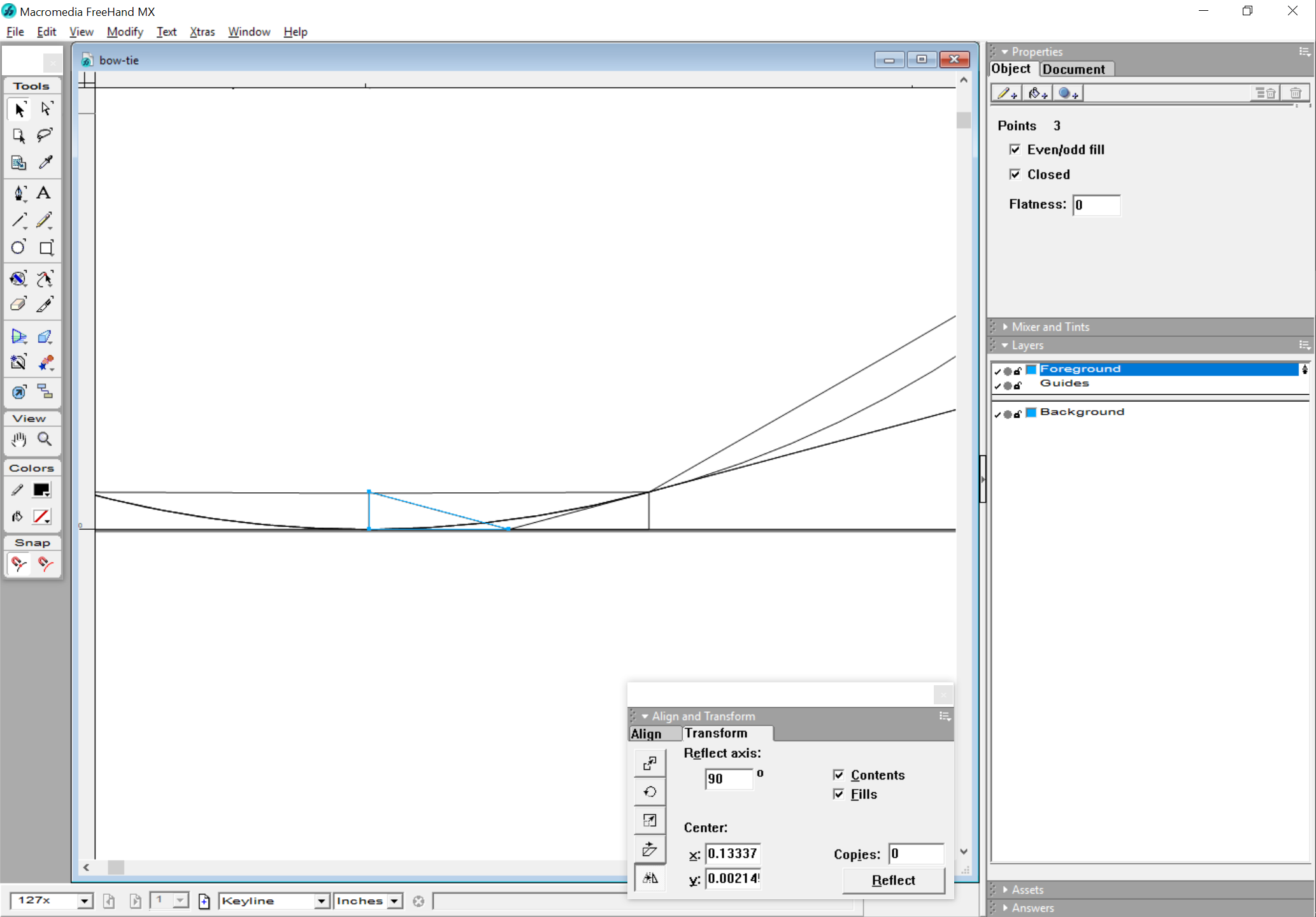
A bit of duplication and flipping (and rotating the circles) allows us to arrive at:
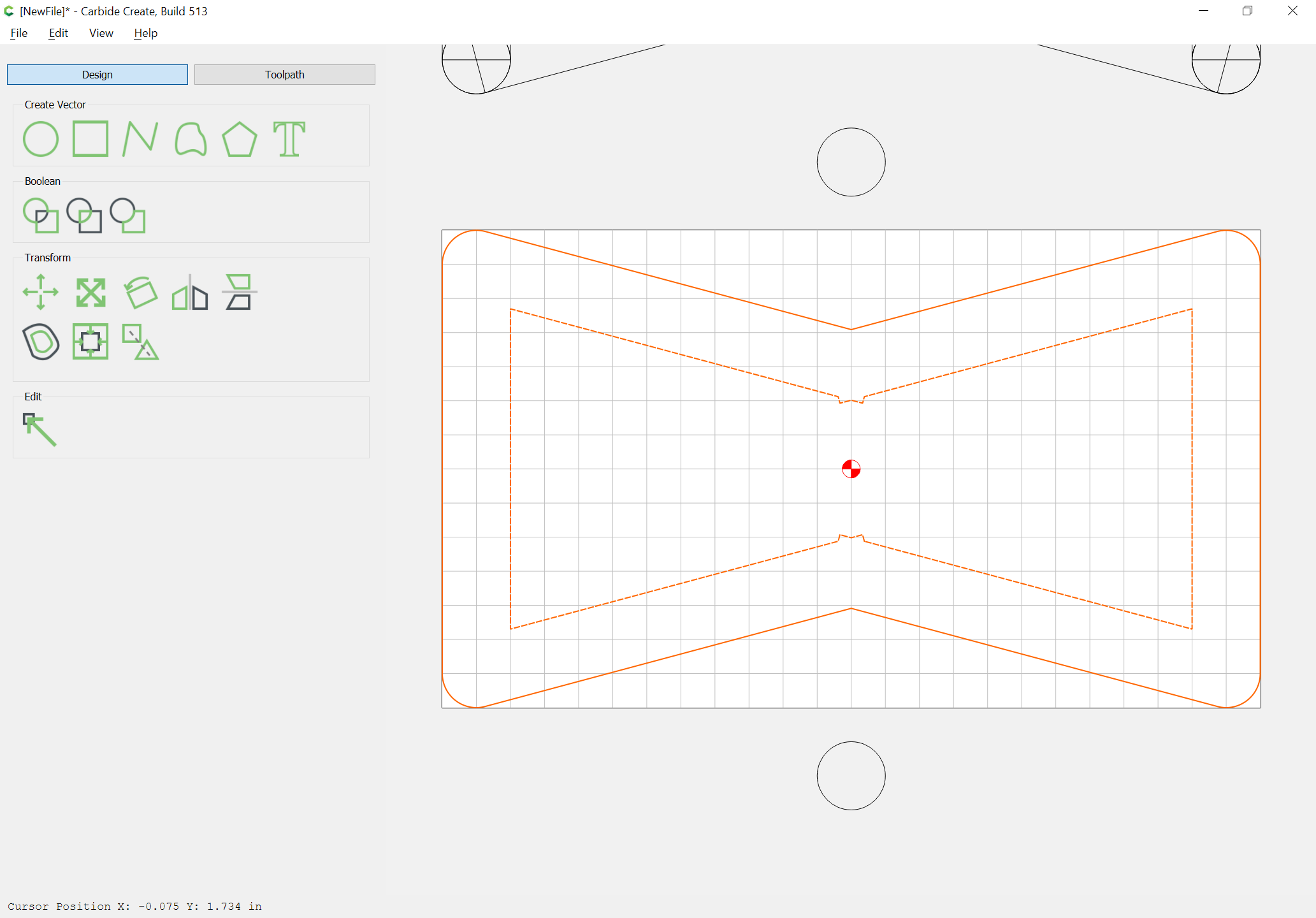
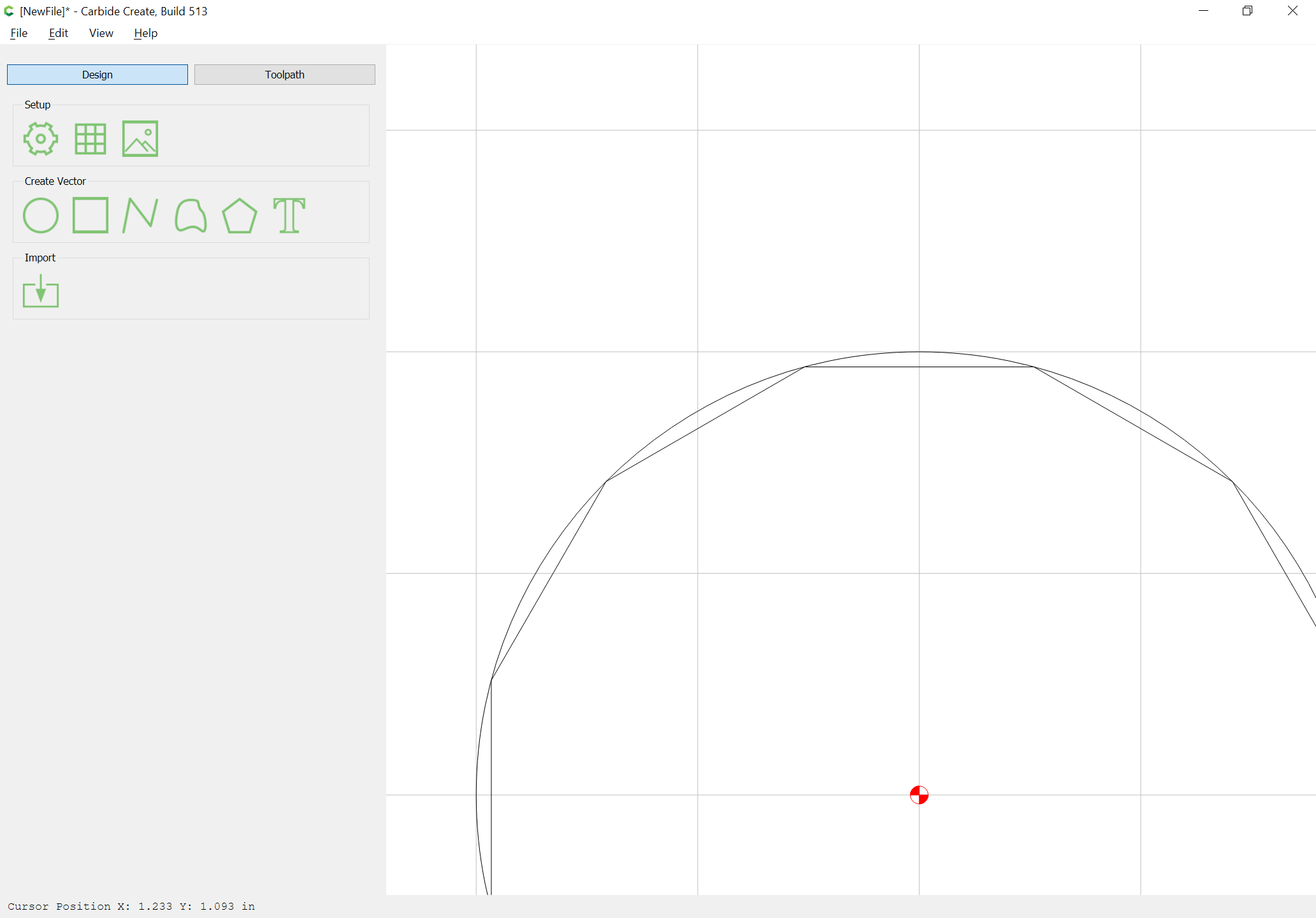
which when unioned yields:
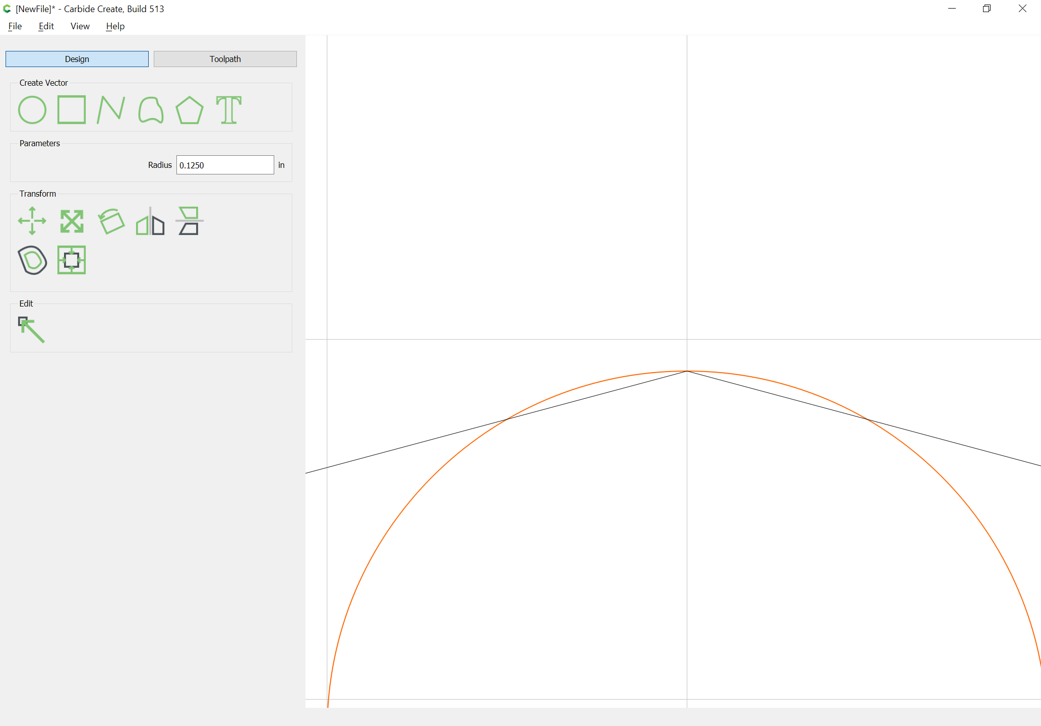
and when zoomed in on, shows a very slight rounding is necessary:
Duplicating this geometry and subtracting the circle from the nascent bow-tie gives us a node we can snap against for measurement purposes:
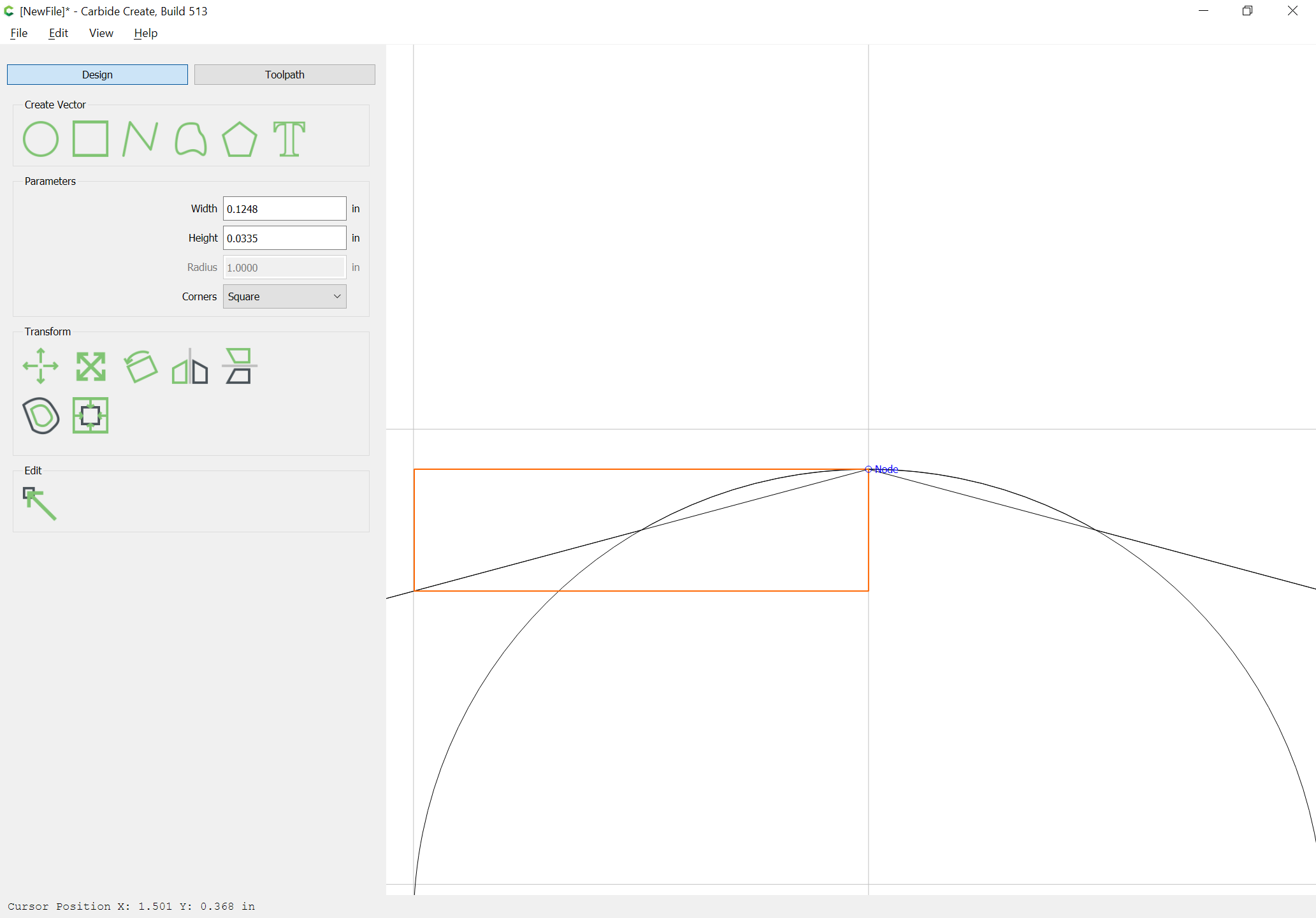
Since Carbide Create only affords an option to draw from the center out this must necessarily be reduced in size by a scaling factor of 0.5 and repositioned.
But we are asking the wrong question — what needs to happen here is we need to inscribe a circle inside a figure which has angles of:
180 - 15 * 2
so, 150 degrees, so a 12-sided figure, so a dodecagon
Carbide Create makes it simple to draw a circle with an inscribed dodecagon (since it draws polygons using the radius to a point):
So the math should be:
- determine the length of the base of a right triangle which has a hypotenuse of radius and an apex angle of 15 degrees
- use that base distance of calculate the height of a right triangle which has opposing angle of 15 degrees
to determine the distance which the circle should be lowered from the point of the interior angle of the bow-tie.
This dimension of course gets re-used in a number of places, so we’ll start at the lower left corner we are using as an origin:
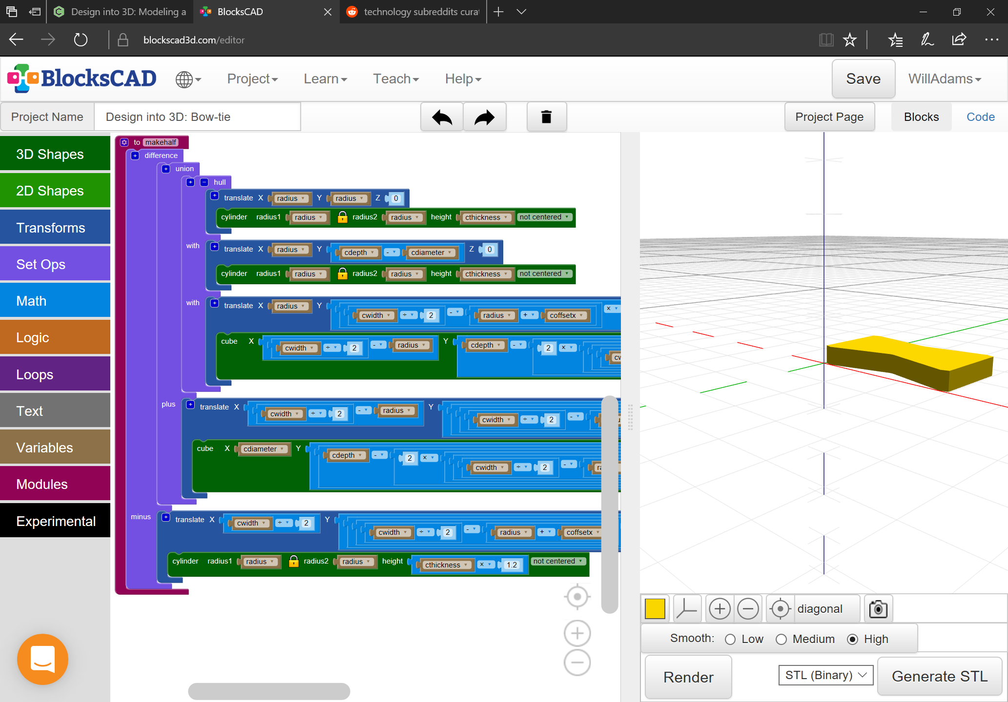
With those numbers worked out, it’s a simple matter to make a module to make half:
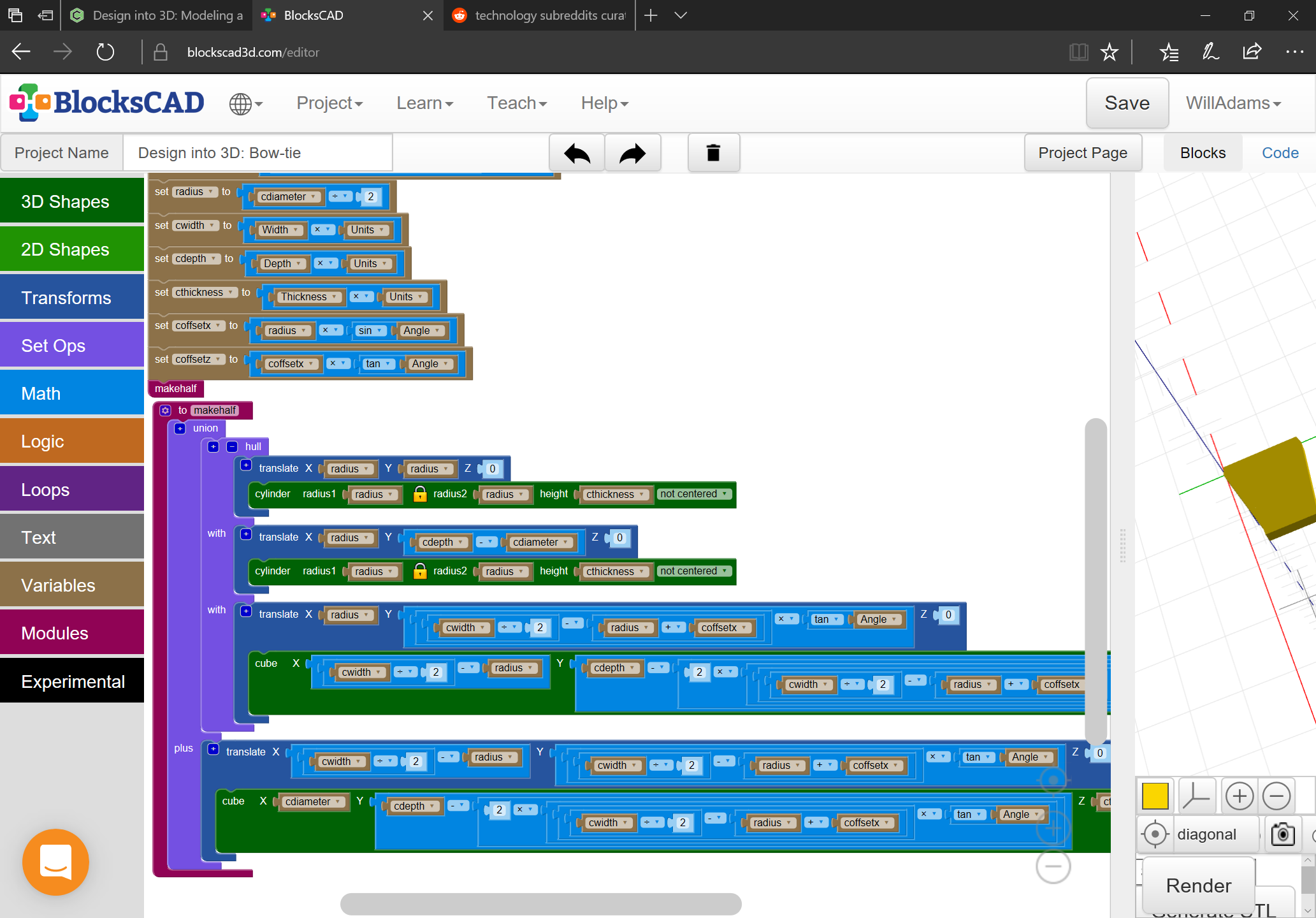
and then to mirror it and place the copy appropriately.
See:
https://www.blockscad3d.com/community/projects/997212
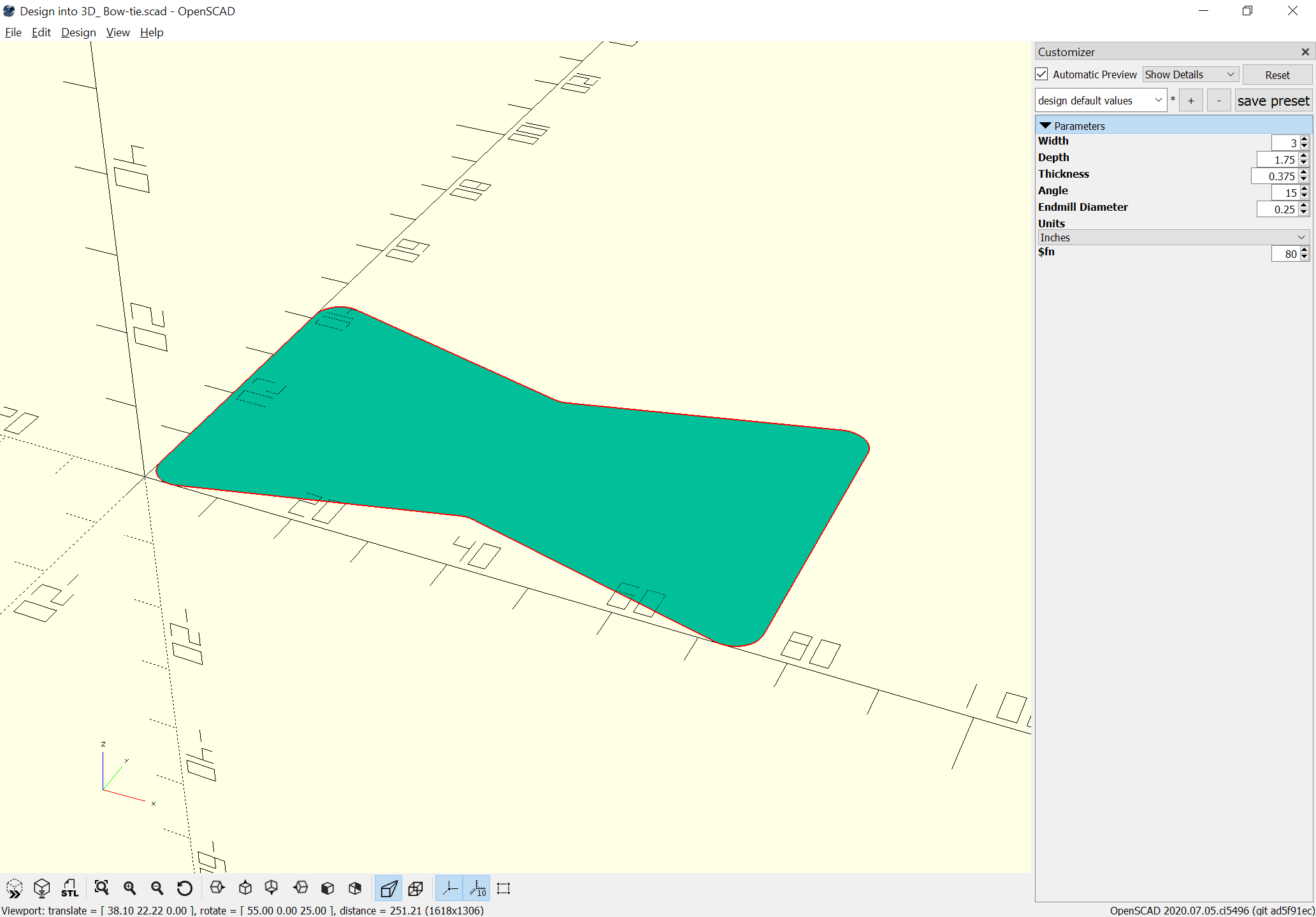
Next is exporting OpenSCAD, wiring up the customizer and adding the projection() command so as to be able to export a DXF or SVG.
Will you have encyclopedic knowledge.
1 Like
Thanks, mostly I’m just stubborn and manage to look up the specifics I need.
1 Like
Very interesting and complete solution. Designing the object with tooling geometry in mind allows for direct machining of both the bow tie and pocket on the machine.
This topic was automatically closed after 30 days. New replies are no longer allowed.