Designing to use hinges

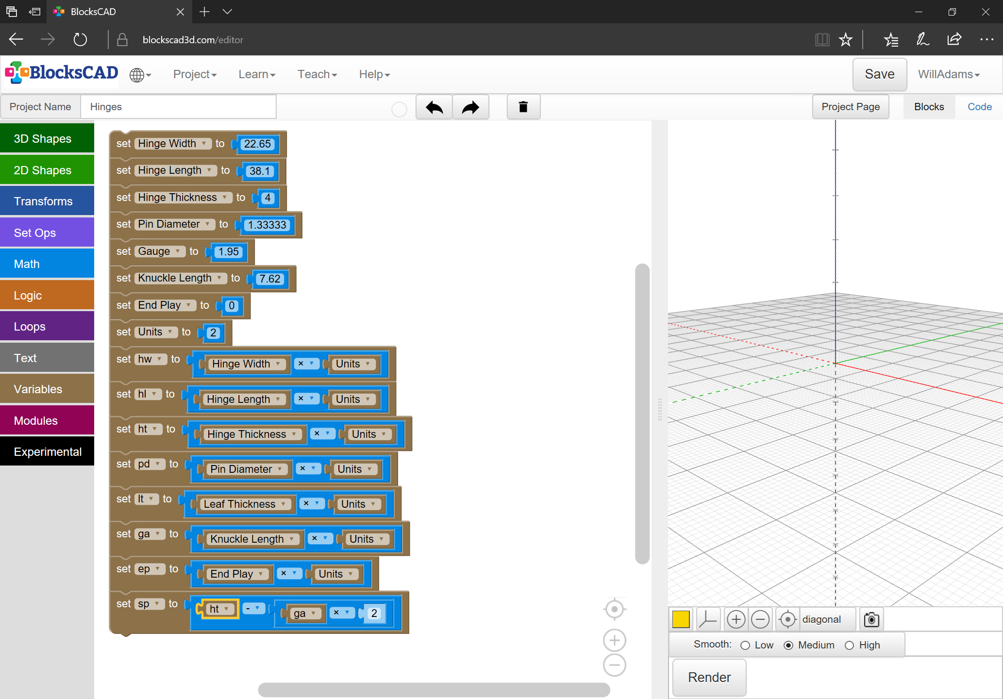
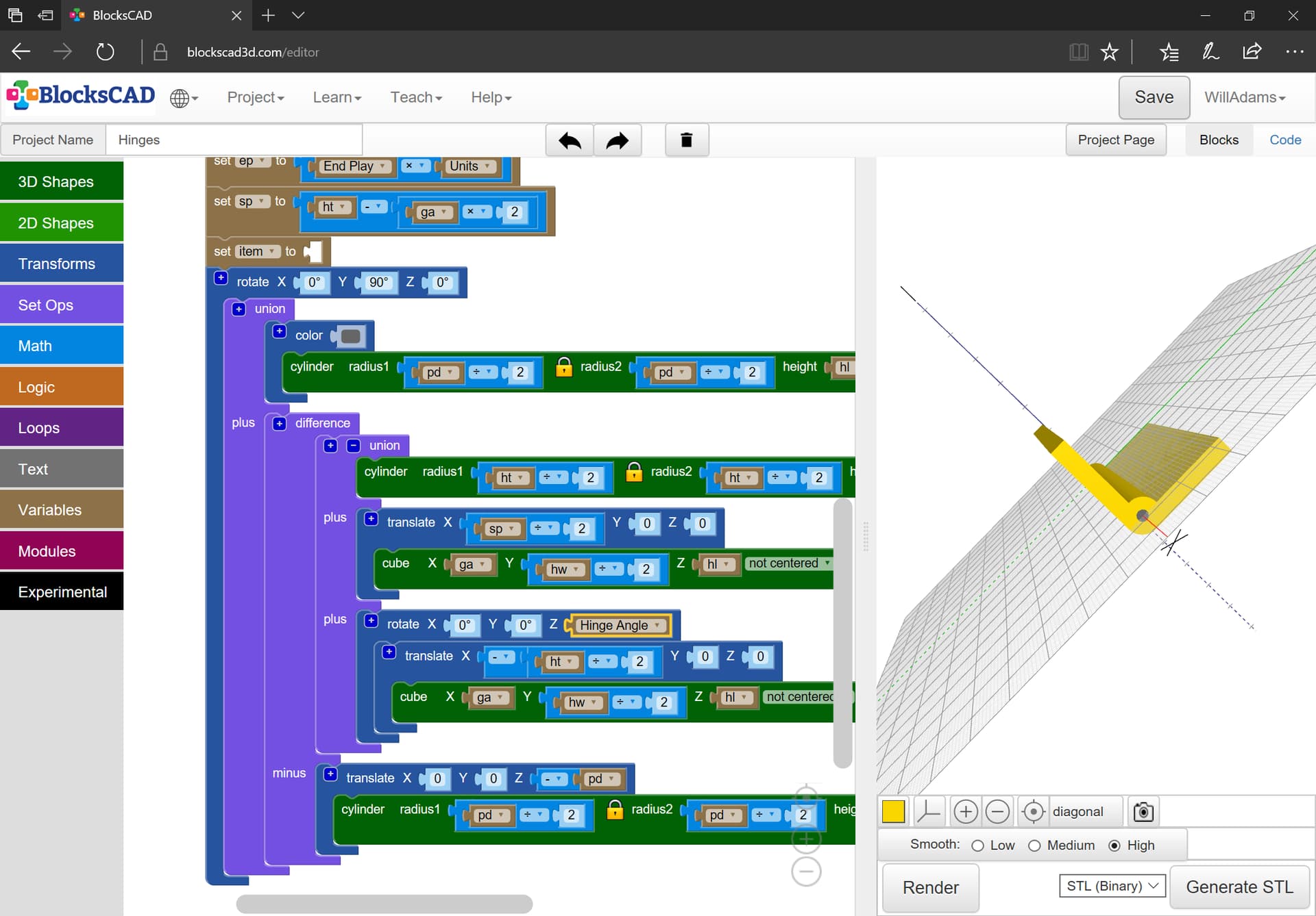
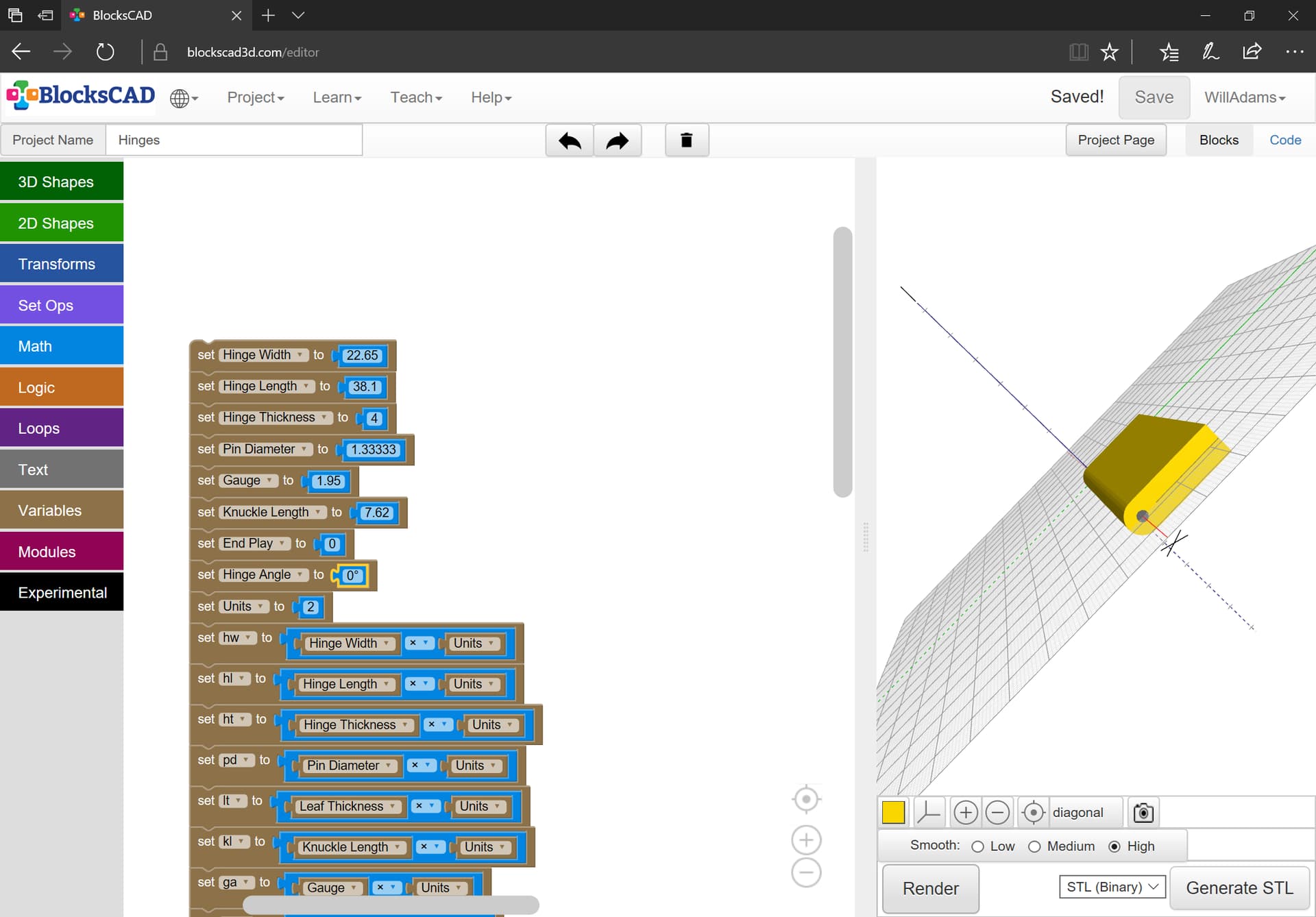
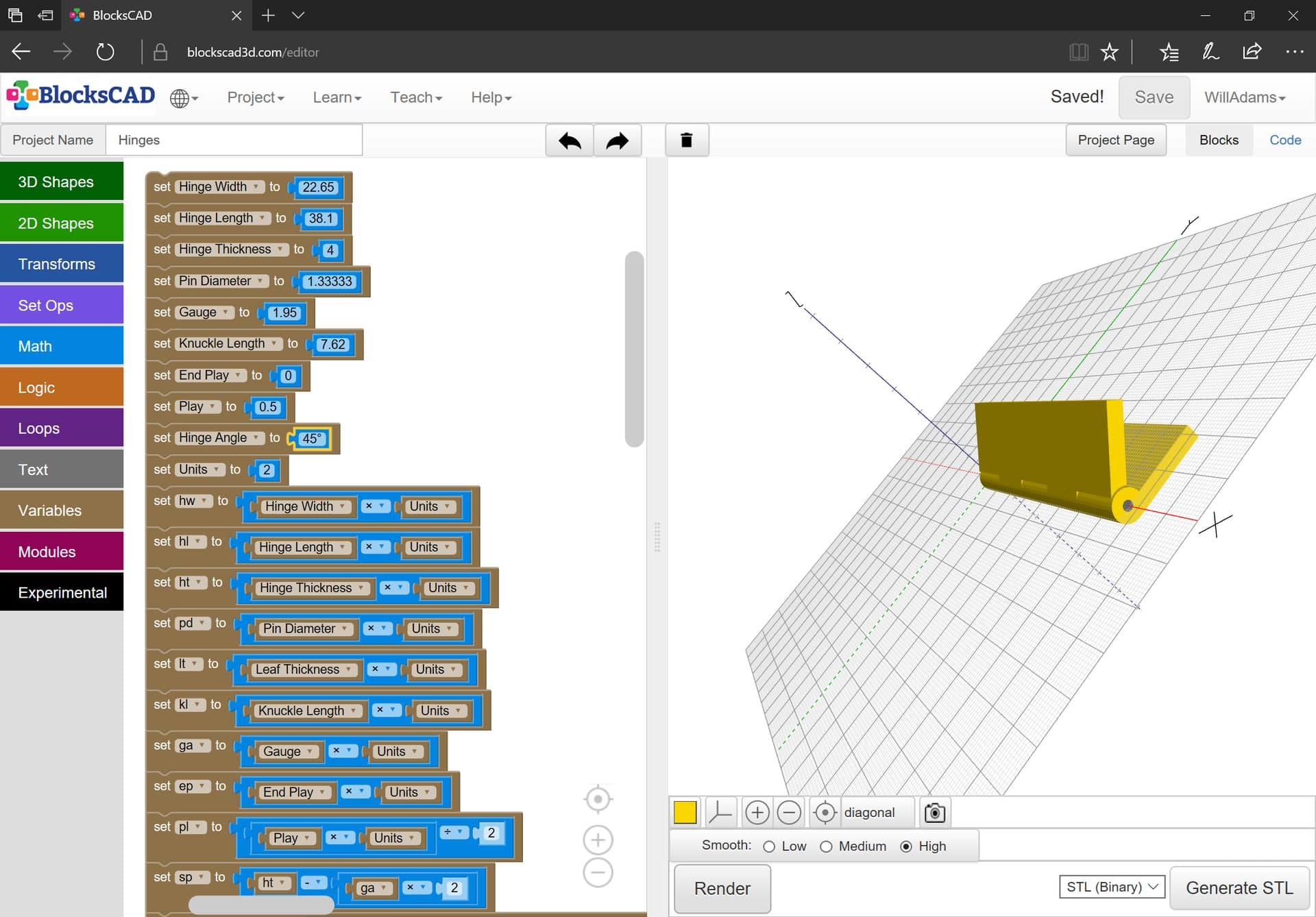
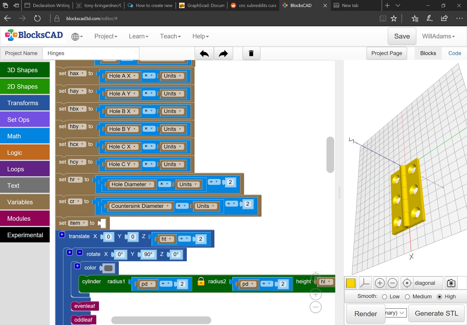
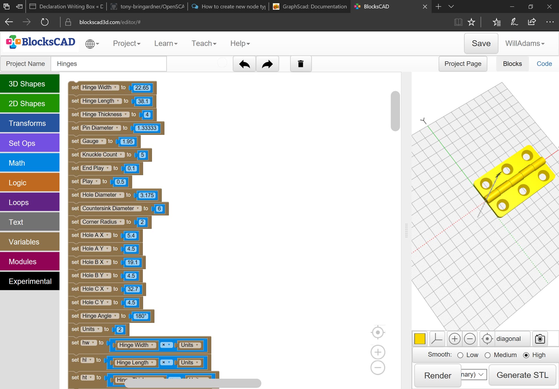
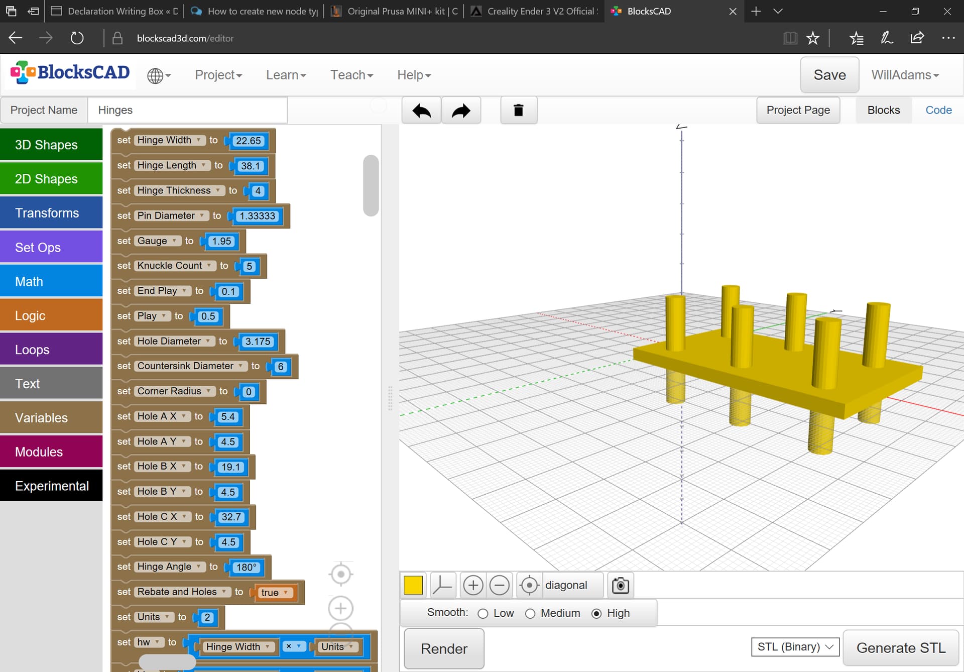
A future project will involve some hinges in a fairly complex set of assemblies, so wanted to be able to make use of them in OpenSCAD, but apparently, they’re not a sort of hardware which anyone has ever used.

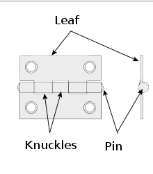
Basic parameters/terminology:

  • leaf — one half of the hinge body
  • pin — the rod which the leaves of the hinge pivot on
  • hinge width — the width of the fully open hinge
  • hinge length — the length of the hinge along the axis of opening/closing
  • knuckle (length) — a part of one leaf which wraps around the pin
  • pitch length — the length of a pair of knuckles
  • end play — the distance between each knuckle
  • swaging — whether or no a leaf is bent so as to alter its position relative to the pin
  • gauge — the thickness of a leaf

A simplified image from Wikipedia:

220px-Basic_hinge.svg

Using the terminology we make variables and calculate them out using units:

Size & spacing of the attachment / mounting holes?
And some hinges have them staggered as well. (Not sure what your niche is for these)

Yeah, we’ll need to address hole size and pattern and countersinking as well, but that should be obvious when we get to it, and might leave it to be done manually.

We also need to add “Hinge Angle” so as to be able to show open:

and closed:

A pair of modules later we have:

In case anyone is curious, the BlockSCAD file is at:

https://www.blockscad3d.com/community/projects/1421975

1 Like

Updated to add support for up to 3 holes:

Last feature, many hinges have rounded corners:

A further requirement is being able to remove not just the rebate for the hinge, but also the holes for the screws.

and lastly we will need to make it into a module and then convert that into a Node for GraphSCAD.

This topic was automatically closed after 30 days. New replies are no longer allowed.