I’m working on making a tool for a mechanical organ project. Valves are operated by leather pouches that inflate and push on a rod. There’s one pouch per note in the organ, so the pouch board in this case has 46 pouched in two staggered rows. I’ve used a single pouch setter in the past, a piece of wood with a flattened dome turned on the end and a port to apply vacuum to suck the leather into the right place so that it can be applied to the wells in the pouch board. In this case the pouches are so close together the leather needs to get applied in larger pieces, covering 6-8 pouch wells at a time.
This is my first go at trying 3d modeling to create a part
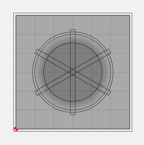
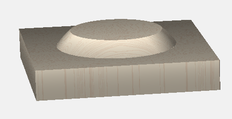
Here’s what the modeling looked like, astonishingly much like what I wanted; convex curved sides with a flat bottom and narrow slits to carry vacuum to the edges of the dome (holes for vacuum supply to be drilled later) :
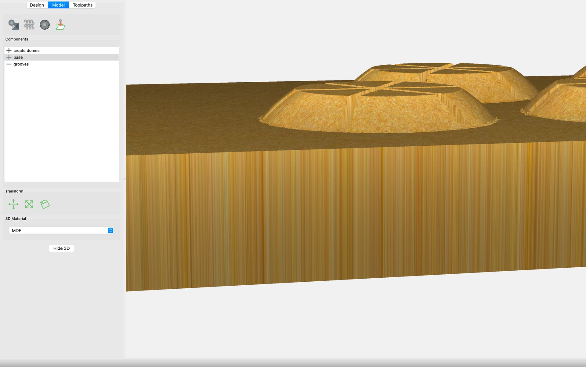
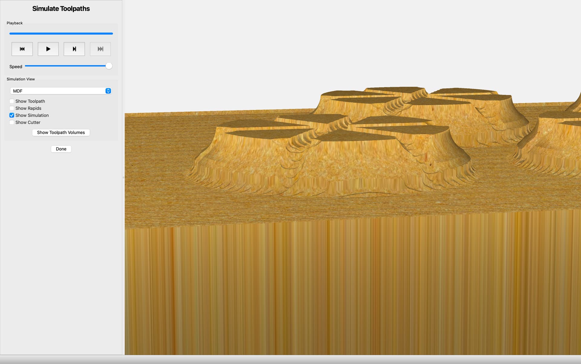
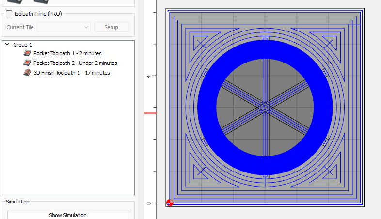
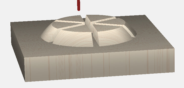
Here’s what I got after applying toolpaths; the edges now have a weird ogee shape rather than a smooth curve, the grooves are much wider than expected, and it all looks pretty ragged
Any advice will be greatly appreciated. I’m also not at all sure how thick a piece of stock I need to start with or what thickness to input into Carbide Motion, as the process, as I got it from the tutorials, was to start with a stock thickness then extrude the flattened domes on top of it.
So it looks like the only 3D portion of the job is the sides of the ‘domes’ ??
So only cut those portions with 3D. Do the rest with 2D
Only model the curved part as well.
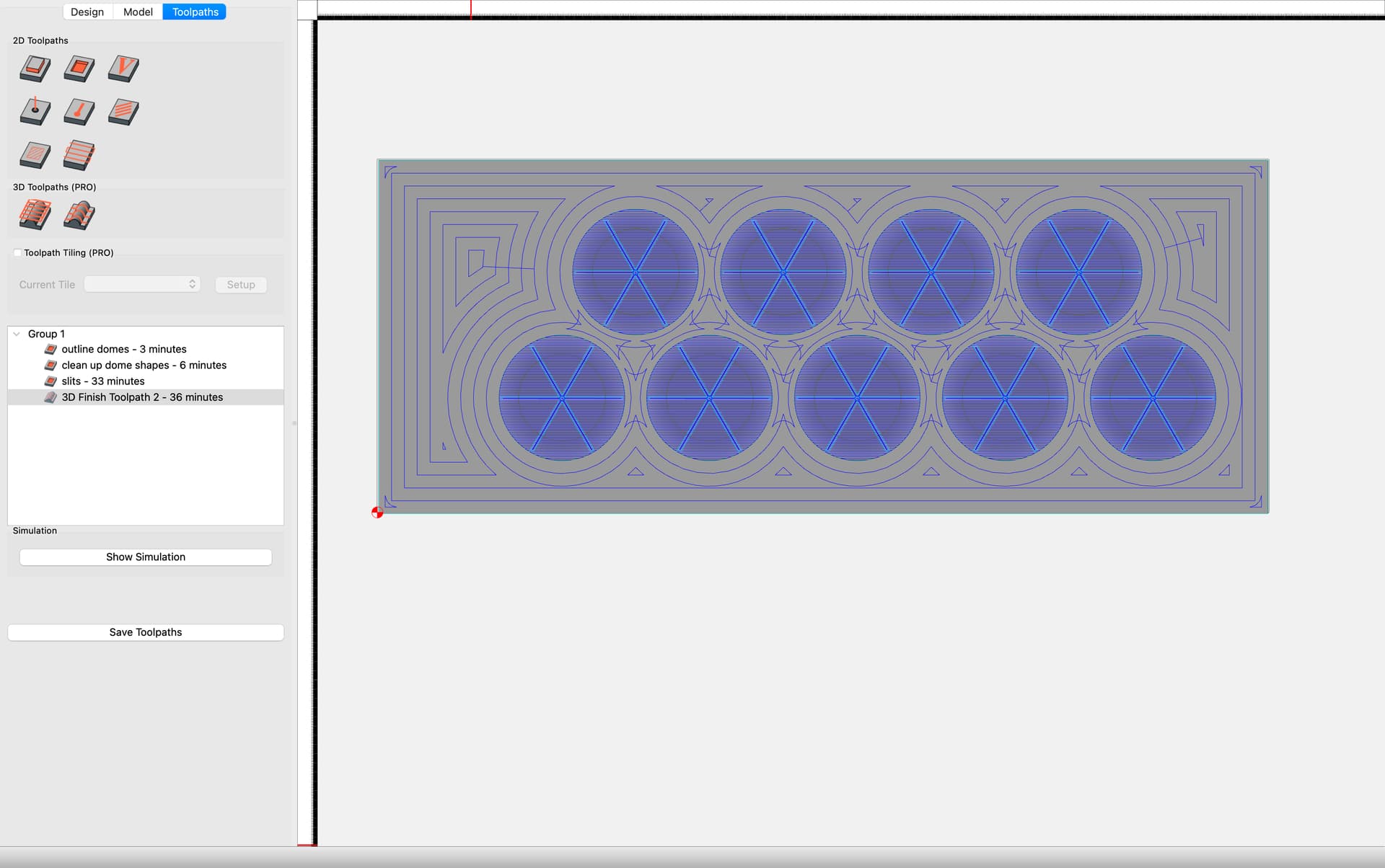
I’m making excellent progress (I think it’s useable as is), but I can’t figure out how you selected only the curved rim for the 3D finish tool path. Perhaps it doesn’t matter but for cutting time. I’d like to learn though.
I see I still have a height discrepancy somewhere producing a trench around the rim, but I will track that down.
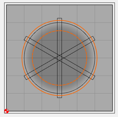
You can constrain the 3D ToolPaths with a selected vector. So having a circle outline selected around the 3D shape keeps the toolpath within that circle.
I have a circle around the shape and the 3d carve is constrained to within that circle; Tod had a second concentric circle and was able to exclude the center of the dome from the 3D carve, so only a donut was included in the 3d tool path. That’s what I was wondering about.
Very early on the learning curve here, sorry if it’s obvious!
Ah, I didn’t see that - so didn’t realize I should have made note on that.
Nested vectors selected will constrain the 3D Toolpath to the area between the vectors - this function works in pairs. So if you have multi-nested vectors selected, the program can come up with a complex-yet-funky selected area for the 3D tooling.
Thanks again, that seems to have not worked for me at first because I had some odd grouping of the vectors. Once I ungrouped everything it worked exactly as you and Joel showed.
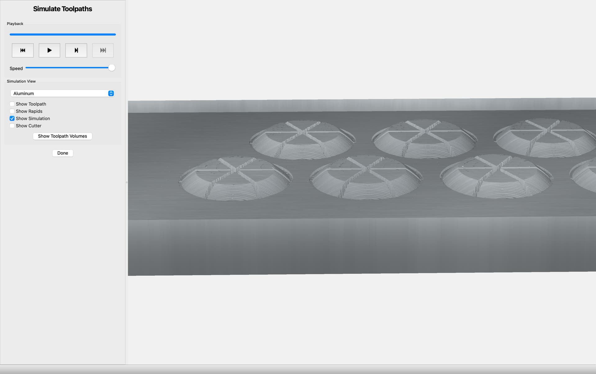
I’ve now successfully made my part, hope to see if it actually works today.