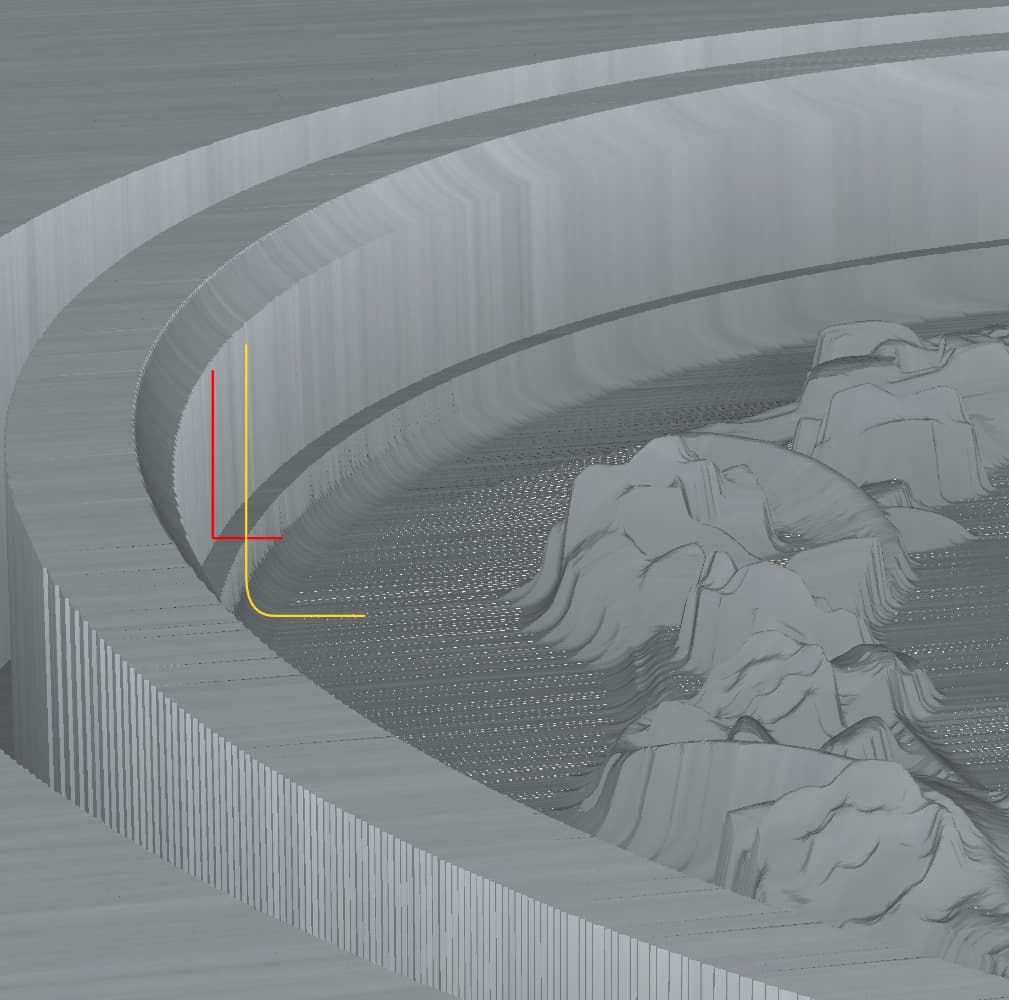
In the image above the red line is a rough pass, the yellow is a finish pass. The Stock to leave was set to 1.0 mm to accentuate the difference and ensure I was seeing the entire width of the finish bit. Both paths use the same ellipse vector as does the path for the cove at the top of the rim.
Notice the cove, which its centered on the path, seems to be truncated before it reaches the horizontal tangent at its bottom. It appears the cove is centered on the path, as it should be, and the finish pass is constrained by the path. I suspect this is also as intended, I remember one of Will’s tutorials showing the increasing of a model outline to accommodate this
But the rough pass appears to cut outside the path. If I increase the diameter of the rough bit, the width of the ledge increases accordingly. If I reduce the path size by half the rough bit diameter, the paths boundaries register.
So it appears the rough pass uses the vector path to limit the center line of the bit whereas the finish pass uses a vector path to limit the edge of the bit. Is this a known thing? Is there a reason for this inconsistency?
The difference is that 3D toolpaths are cut to the center of the tool, so you will need to adjust the geometry for the selection in/out by the difference in radius of the smaller tool for it to also cut that region in the same way.
Not completely true. The rough pass cuts to the tool’s center, the finish pass does not.
Take another look, both passes used to cut the field are 3D passes, one rough, one finish. Using the same vector their boundaries do not align.
I can, of coarse, adjust for this with two separate paths. I was curious why CC behaves this way, it seems illogical. I’ve seen this issue on recent projects but only now have sussed out the origin of the mismatch.
Both tools are cutting “ON” the boundary, center of tool. The tools are different sizes so the bigger tool cuts further into the stock. And they are both cutting outside your boundary.
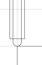
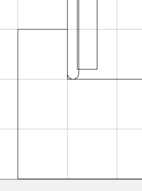
What do you mean by “Create a wall…” and the included drawing?
I know a way to handle this now that I know what’s going on. In this case I need three ellipses for paths instead of one. One for the center of the cove which will define the actual edge of the field, a second for the rough pass inset half the bit’s diameter, a third for the finish pass inset by half its bits diameter.