Dimensional accuracy on a Nomad 3

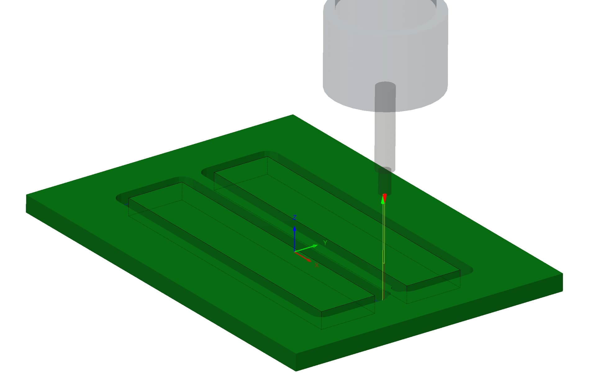
I’m looking for advice on how to improve cutting precision on a Nomad 3.

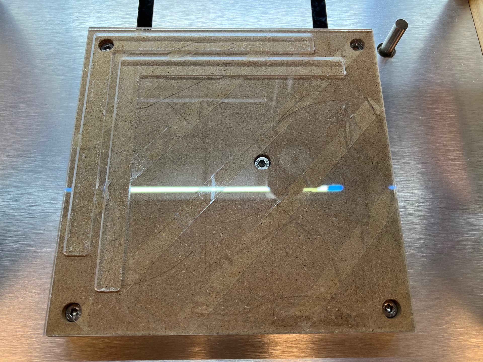
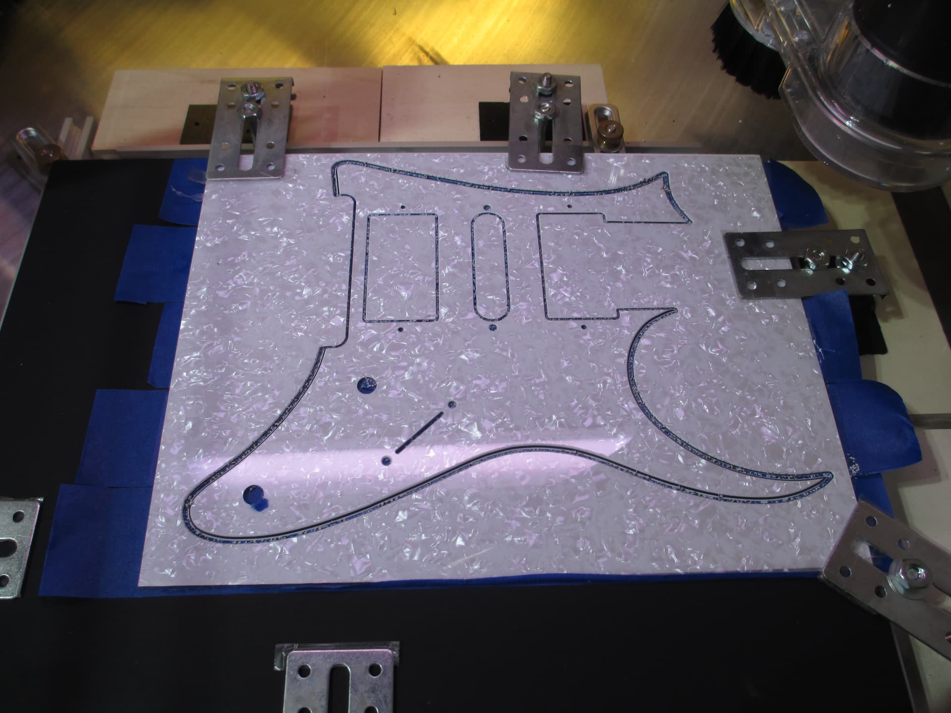
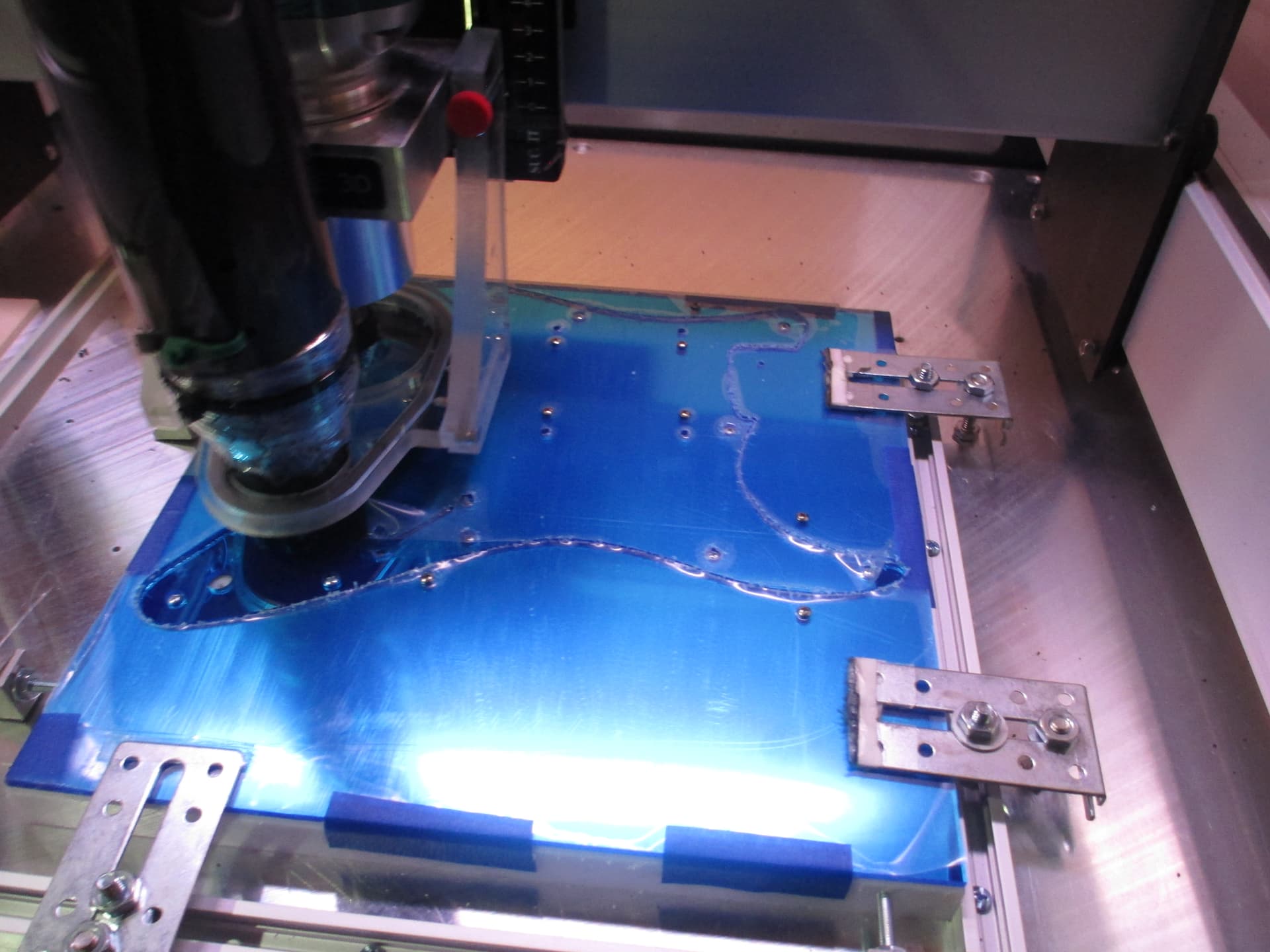
I cut out some parts in acrylic (PMMA, extruded), and I was surprised to find them all slightly too large. 16.1mm instead of 16.0mm, 200.0mm instead of 199.7mm. It mattered, because these were for a mechanical assembly where some parts were 3d-printed and some were CNC-cut. Stuff didn’t fit together.

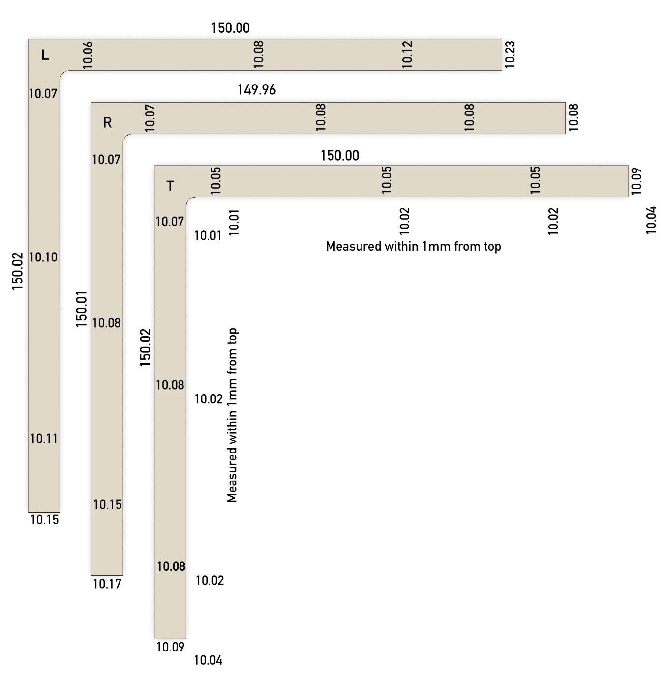
I investigated and followed some of my suspicions and did test cuts in a piece of PMMA (cast). The test piece was designed as 50.00mm x 10.00mm. Here’s what I got on that test piece:

Climb milling (left sideways compensation in F360): 50.06 x 10.09, so off by +0.06 x +0.09.

Conventional milling (right sideways compensation in F360): 49.97 x 9.95, so off by -0.03 x -0.05.

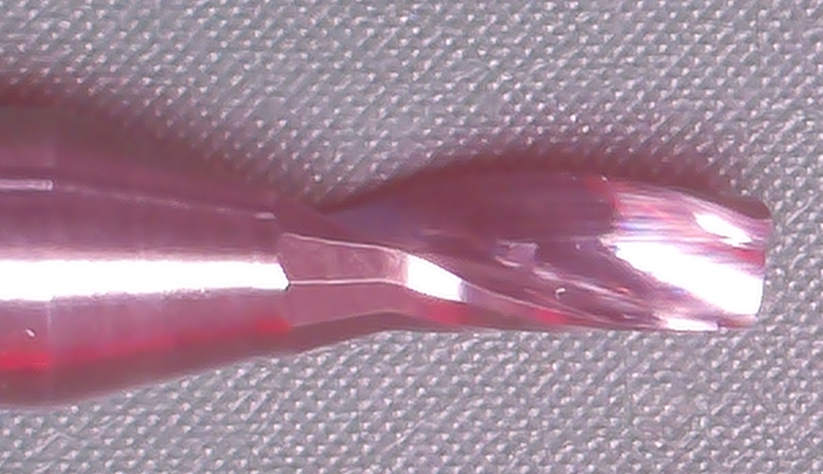
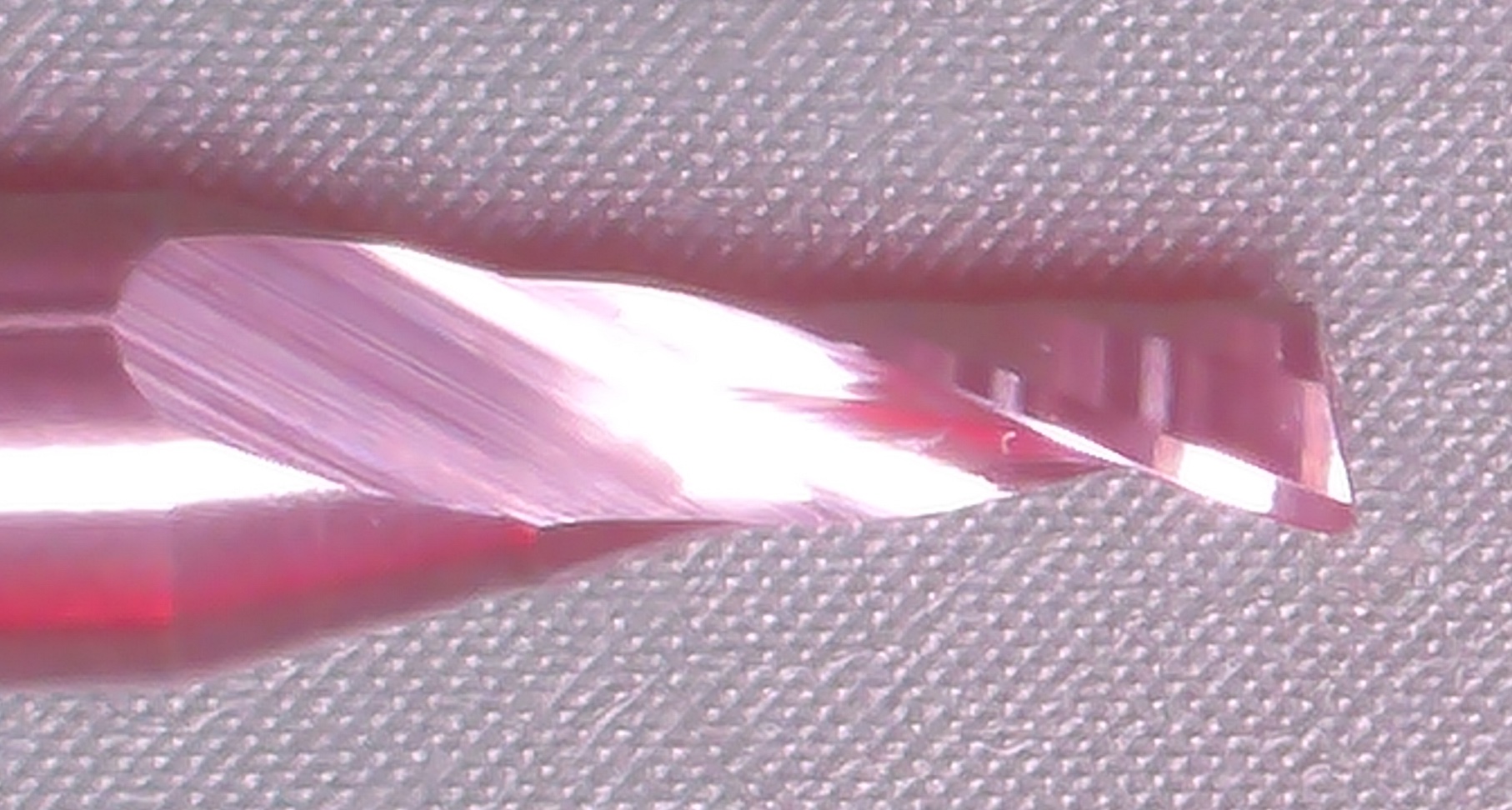
The endmill is a single-flute 2.0mm diameter 4mm length (SP1F-D2.0-L04, dreanique) at 24k RPM, feed 900mm/min, so fz=0.0375 mm. I am cutting in two passes, 1.5mm per pass, as the PMMA is 3mm thick.

I can’t really slow the feed down, because PMMA will melt. Lower limit for extruded PMMA at 24k RPM is around 800mm/min, cast PMMA can take 600mm/min.

The endmill hasn’t seen that much use (and only plastics), it looks good to me (e.g. not worn or chipped).

The question is: where do I go from here? Would you suspect machine rigidity? Endmill deflection?

I can’t afford +0.3mm on a 200mm piece. I would like to be below ±0.1mm, and ideally closer to something like +0.03-0.05mm.

Do I look for a different endmill? Do I stick to conventional milling and hope for the best? Do I slow everything down?


That the dimension is so different between cutting directions would seem to indicate mechanical deflection of some sort.

Have you tried leaving a roughing clearance equal to your chipload and then taking a finishing pass? If that takes too much or not enough, then try adjusting the effective endmill diameter in your CAM.

As @WillAdams suggested it may be bit deflection. However there are changes you can make in gbrl controller for the number of steps your stepper motors take. Look on the forum for calibration method. You change the parameters of the number of steps the X and Y motors take to move a given distance. Basically you cut some circles and squares and measure them, change the settings and recut the circles and squares until you get the exact measurement.

However fix your deflection first if that is the root problem. But if you are consistently off by a consistent amount then the calibration should help.

Hmm. Would I be correct in thinking that trying to cut several different lengths would provide additional answers? If it’s a deflection problem, the error should remain constant, regardless of the piece size. If it’s a calibration issue, the error should grow with distance traveled, e.g. with piece size. Does that sound right?

I’m also thinking that the clear difference between climb and conventional milling points to deflection rather than calibration, unless both errors somehow compound.

Would slowing everything down help with deflection? E.g. go down to 12k RPM and 450mm/min?

I’m also slightly worried about the deflection hypothesis — endmills do not get much shorter than what I use here, so deflection would happen in the collet, spindle and the entire gantry, rather than just a long endmill.

The difference between climb and conventional seems to point to deflection. Have you been doing roughing and finish/spring passes, or just the single toolpath?

2 Likes

Just a single toolpath, with two passes, each 1.5mm deep. So, slot cuts, basically.

I’m just looking for advice on what to try next. If the general consensus is that I should do a roughing pass first, I’ll do that.

1 Like

Yes, folks have done the math to determine what the error is based on measuring multiple lengths of cut.

The other approach is to rough cut things, measure what/where things are cut to, then adjust the CAD/CAM file to finish the cut.

1 Like

Well, I am cutting gears, so that approach won’t (ahem) cut it :slight_smile: Anyway, I think I have some idea of what to try next. I guess one of the incidental takeaways is that a laser cutter might be a better tool when you want precision-cut acrylic.

1 Like

If precision is the goal, a strategy where your toolpath does a small cut for a finishing pass, then repeating the finishing pass (often called a spring pass) is the way to go.

I have a laser at my disposal. I consider it much less precision than a Shapeoko/Nomad. The kerf can be infuriating to dial in.

4 Likes

So! Following up on this excellent advice with real-life results and measurements!

I created a test setup with an L shape, 150mm long in both X and Y, and 10mm wide. I then cut it using three different setups:

  • L setup: left compensation (climb milling), leaving 0.2mm, finishing pass, and then another “spring pass”. All this repeated for two depths.
  • R setup: right compensation (conventional milling), leaving 0.2mm, finishing pass, and then another “spring pass”. All this repeated for two depths.
  • T setup: left compensation (climb milling), but with tabs and a finishing stepdown. So, the first depth gets done to within 0.2mm, then the second depth, but leaving 12 4mmx0.4mm tabs around the piece, then the finishing pass happens, then the spring pass. Cutting the tabs comes last.

I came up with the T setup idea after cutting and measuring the first two. The results weren’t bad, but the part was getting progressively wider away from the corner. I figured it’s a workholding problem: the two-sided tape just can’t hold the narrow piece well enough. And the “T” results seem to confirm this: using tabs, I got more consistent width.

Here is the machine before cutting anything and right after cutting the first two pieces. You can see the double-sided tape underneath.


Now for the results. First, all of these are better than my previous attempts, and your suggestions of additional finishing passes (and a spring pass) were spot-on! Thank you!

The image below shows measurements along the entire XY length, as well as width measurements. For the last (T) piece, I also measured the width within 1mm from top, because I suspected that it’s the bottom that has more problems, which was true.

I think the biggest thing influencing the precision right now is workholding and stock flex, but I can’t think of a better way to hold down acrylic. But there is no reason to obsess over this: one should remember that even Mitutoyo calipers are only ±0.02mm, and I’m not looking for crazy precision here.

Overall, I’m very happy with this result. No calibration needed, the machine is fine, as is the endmill. Good workholding and careful cutting strategy got me to where I need to be. I intend to try some more approaches where the piece isn’t cut out until the very end (e.g. held by the entire stock area, not just tabs), but even these results are good enough for the kind of stuff I’m making (gears and irises at this time).

5 Likes

Great way to science it out!

I have an SO3, but these workholding methods should still apply to your Nomad…

I cut thinner plastic sheets, mostly extruded acrylic, kydex, and PVC. To start with, I use an HDPE mountboard that is tapped for #4 sheet metal screws in strategic locations (more can always be added). On top of that I usually have a super-thin (0.8mm) sheet of sacrificial plastic. My workholding consists of either using the ‘painter’s tape - superglue - painter’s tape’ method seen here or by using downward clamping pressure, preferrably with tight tolerance #4 pilot holes in the target-plastic stock.

This first pic shows the ‘tape’ method (pic 1):

These next pics show the ‘downward clamping pressure’ method (pic 2 and pic 3):

6 Likes

As mechanical designer for over 20 years I will say one thing that most makers have no idea of: accumulative tolerances. Each machined part, piece of sheet metal and plastic piece, etc. all have a tolerance.
It does build up over dimensional space. This is something to take into effect when creating parts (sorry, it’s more involved and you need to take a class on geometric tolerancing or mechanical design,)

With that being said. If the nomad is like other CNC machines, you need to get a dial indicator create a tram to sweep it across the table bed and adjust the router, table etc. Also make sure your belts are the correct tightness and are not stretched out (I think they have a update kit for that). There are a bunch of videos and texts out there to show/tell you how to check and dial in your system.

Even in the most accurately dialed in machines there is a tolerance and that cannot be changed, i.e., you have a piece of bent sheet metal. The tolerance over a bend is a lot greater that the accuracy of a hole in a flat sheet of metal; +/- .003" for a hole in a flat sheet (but that can change by how many holes are stamped into a sheet) and over a bend it will be on average +/- .010". How do you handle this? Larger mounting holes, slots, etc. Think about over three bends, or plastic to sheet metal? You need to understand the process and the design.

I guess what I’m trying to say is just because you dial in the Nomad, the design may still not fit as you thought.

Years ago, they (companies) had designers who started as drafters. With the advent of CAD/CAM the got rid of the people who specialized in designing and making drawings and pushed it on engineers. Now we have engineers who cannot even make a good drawing to use in publications let alone a standard mechanical drawing., I taught CAD/CAM at a top 100 and saw the changes and the crap that was spewed out, the same as the tech pub industry, Ventura Published made it so we didn’t need layout people. Like that was the only thing they knew (was to type) so a person who can type knows how to make a wonderful publication that is that easy to read. NOT! White space, kerning, leading! Knowlege of the process!

OMG I’m ranting! Hope the above helps.

4 Likes

@BK12 Oh, believe me, I know very well that I have no idea what I’m doing — I’m acutely aware of that, hence my asking for advice. At this point, I learned that the biggest source of my problems is workholding and the material itself.

@downrazor11 Thanks! This is quite helpful — I can’t really use screws with the parts that I’m cutting out, but I could use them for stock that will be left over. And I completely forgot that tape+superglue works well and can work for acrylic, too — I’ll definitely try that.

1 Like

This topic was automatically closed 30 days after the last reply. New replies are no longer allowed.