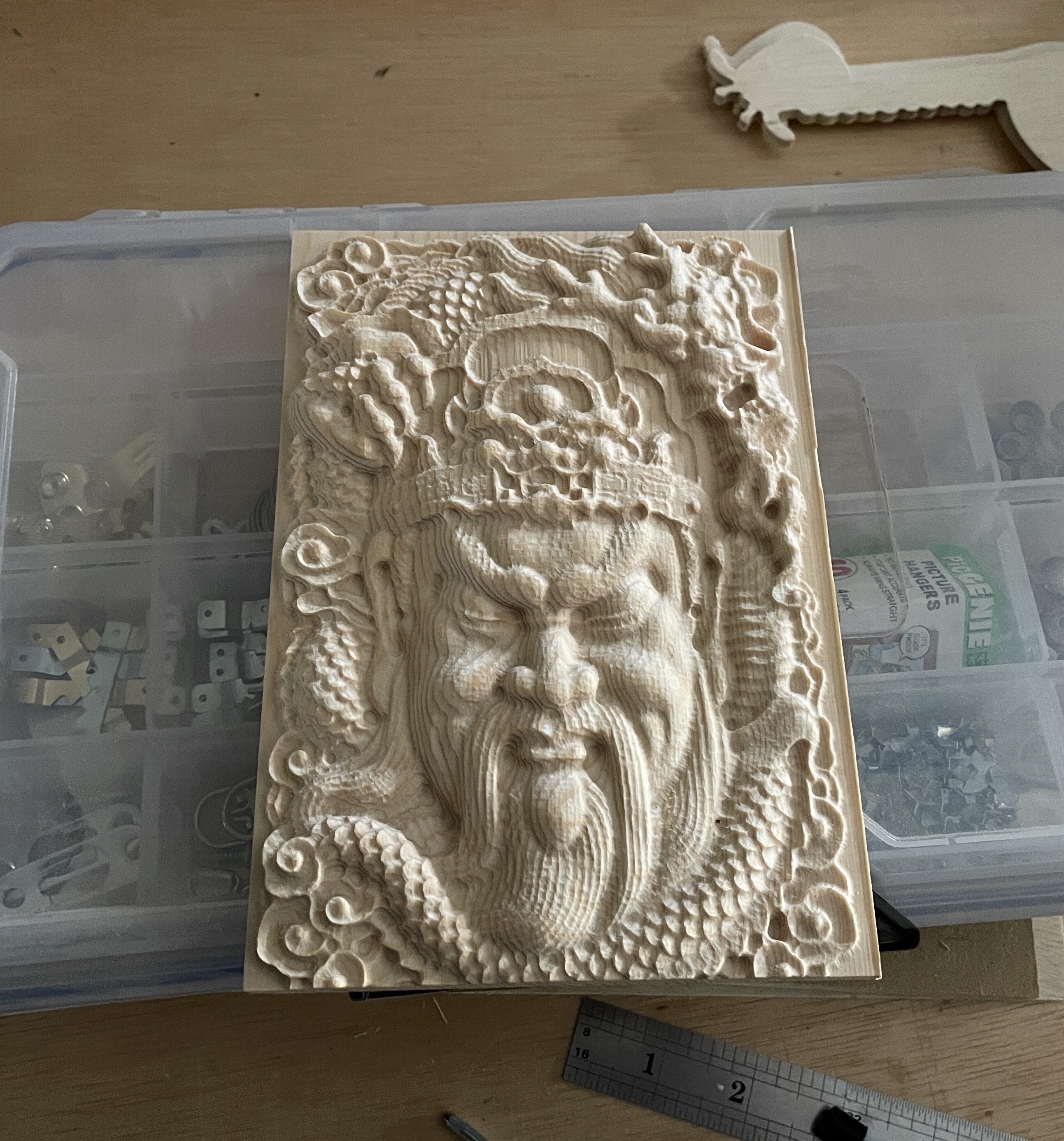
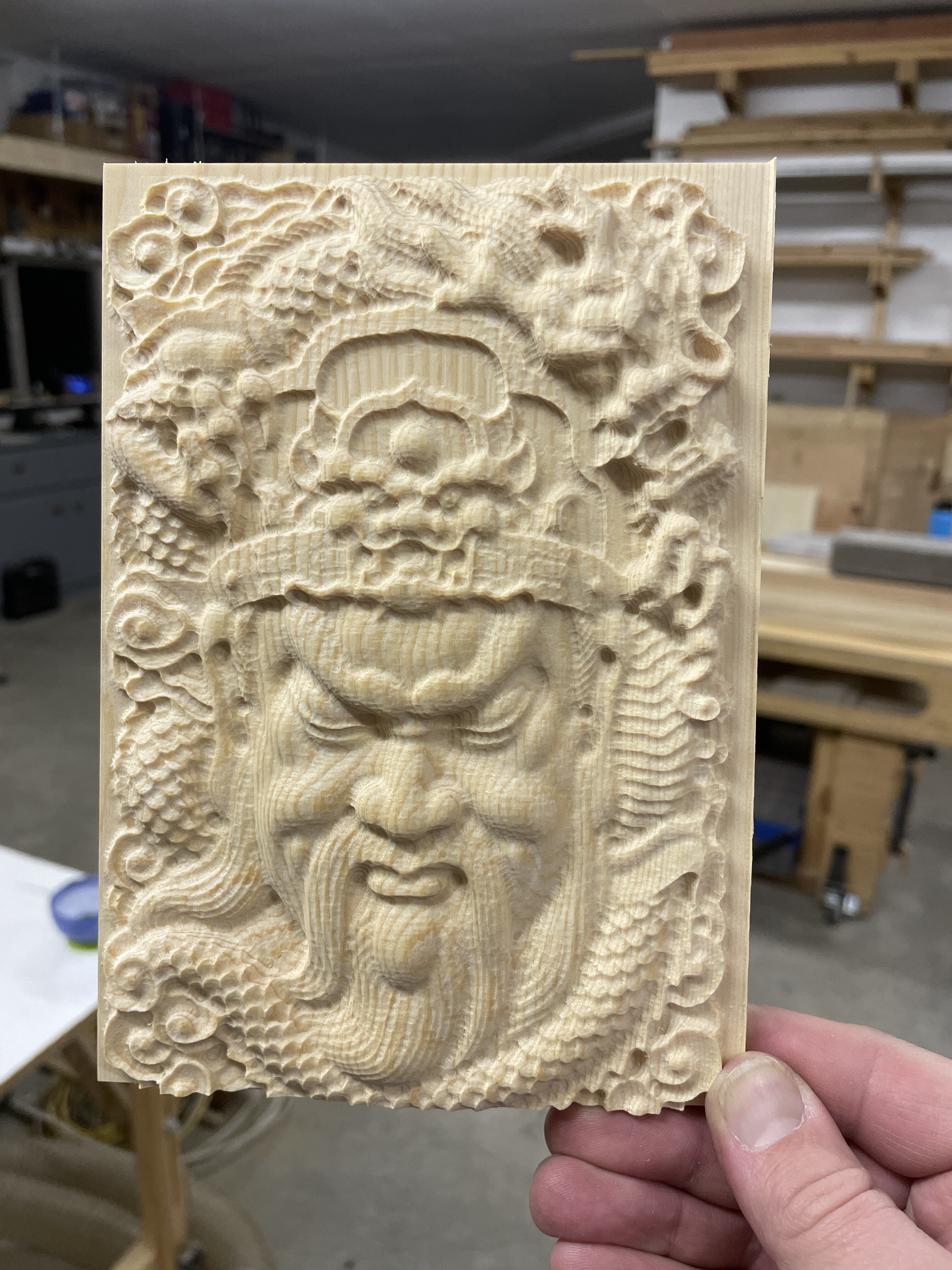
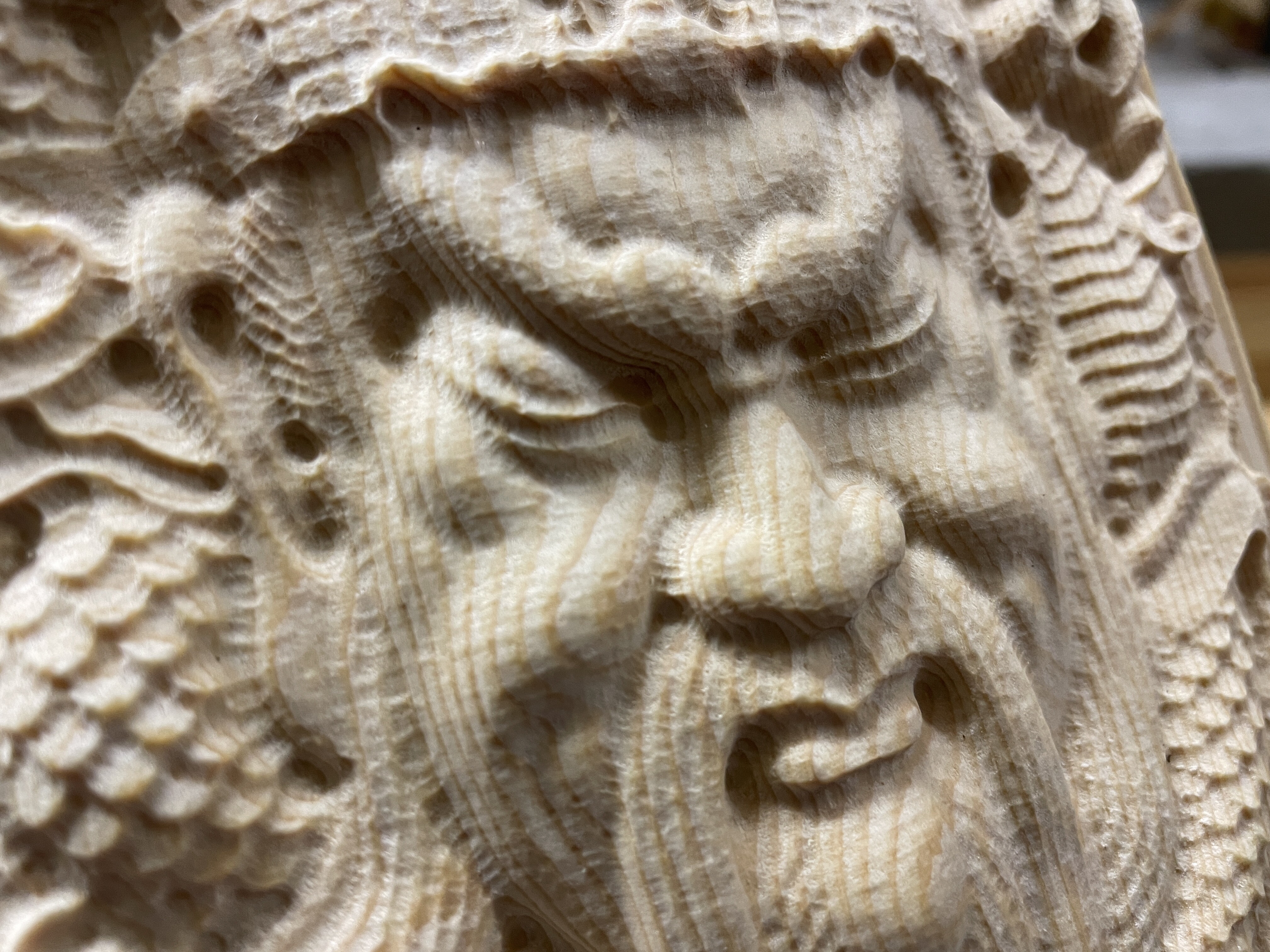
Tried my 3rd 3D carve. Does any one know why it ended up “dimpled”? Some know issues.
• small canvas (5x7)
• soft pine
• 1/8” ball nose. Should be a 1/16”
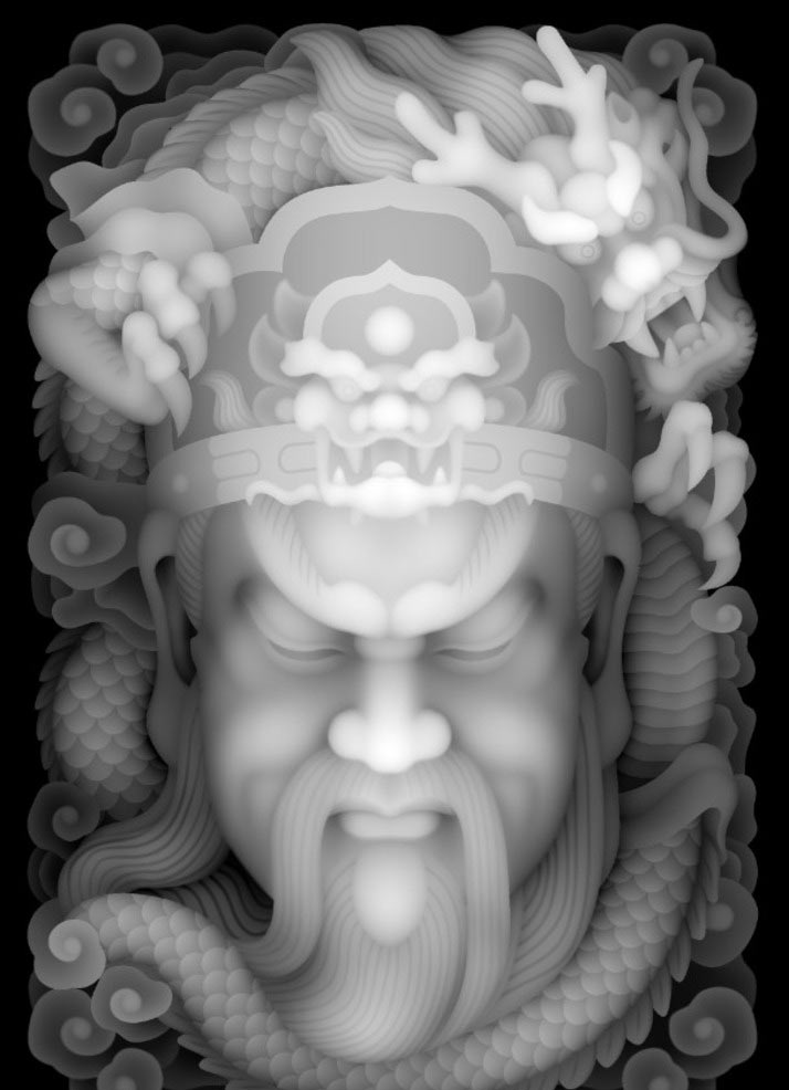
The source height map wasn’t super duper high res but also not very small
I thought it might just be the wood grain, but the dimples don’t really line up with the grain
@WardGross the file was created using Model Resolution: Standard
which when exported as a PNG is 817 x 1,225 pixels (including some empty area at top/bottom.
If you slightly reduce the stock size to match the proportions of the image and increase the Model Resolution to “Very High” you should get a better result.
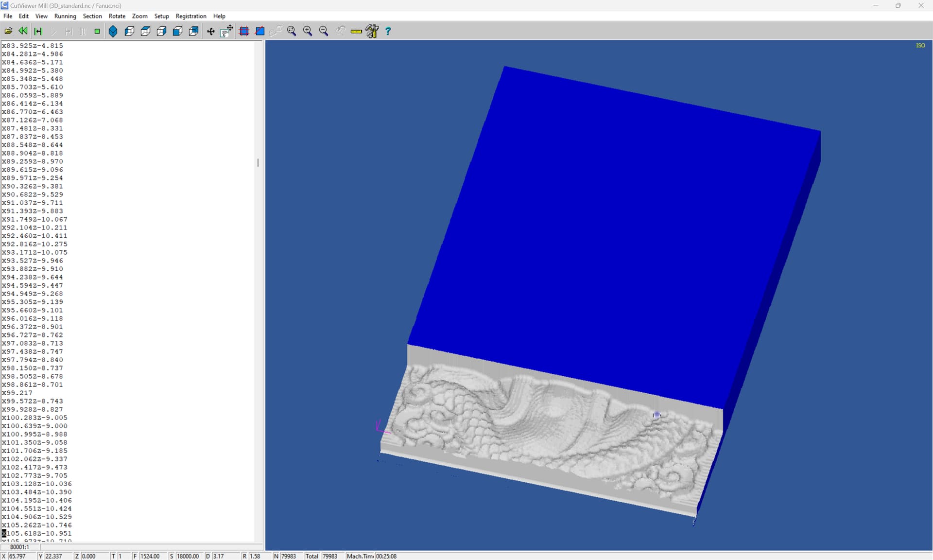
(well, begins to, unfortunately my G-code previewer halts randomly for some reason on my new computer)
which seems to show the dimpling, so hopefully the higher resolution model/setting will help. Also try increasing stepover and running a second finishing pass at a different angle. If model geometry allows, you could go down a toolpath size, or even two with a 3rd finishing pass.
This was simply a height map image that I took a screenshot from a google so I don’t have the actual model to export as a higher resolution. I’ve been a graphic designer for 20 years and realize the ill effects of resolution when it comes to real life things like print, so this makes sense here as well.
What do you use for a G-Code previewer. That seems like it could be really handy especially when using nicer (more expensive) wood species
100% just a practice piece but learning more as I go. Thank you for your investigation and response.
I use CutViewer, but it is unfortunately orphaned (literally, the developer passed away) and as noted above, developing problems where it won’t finish generating a preview sometimes since loading it into Windows 11.
I’m probably going to see if I can adapt:
to be a general-purpose G-code previewer — but that needs for me to finish it, and then get much better at Python.
It determines the resolution of the pixel image used for the 3D model.
You can see this quite vividly by making a 1" x 1" square stock, modeling a circle in it, setting up toolpaths and viewing the 3D preview in toolpaths, then repeating the operation for a 48" x 48" stock, but the same size circle.
wonder if I just need a smaller bit. The 1/8" is a bit big and doesn’t give the detail. I also may have made the relief depth a bit much too. I guess chalk it up to learning the machine and process. Still loads of fun watching it buzz back and forth and magically make a carving. Cheers!