As requested by Sarge013, I have put this together for anybody interested in building their own DIY custom keyboard.
This is a long multi step process that involves ordering a PCB from a PCB manufacturer. It is rather simple but ultimately a time consuming process.
Step 1. Decide on desired keyboard layout.
I used a free keyboard layout designer that can be found here: Keyboard Layout EditorMy design uses 20 keys that have extra spacing between the jog keys and all other keys. It is easy to add additional keys if needed as the micro controller used for this project is a ATMEGA32u4.This means that there is 26 GPIO pins that can be used for buttons. If you do a matrix as I will show you later in step 3, then that means you can have a maximum of 169 keys that can all be pressed at once with no key roll over(NKRO).

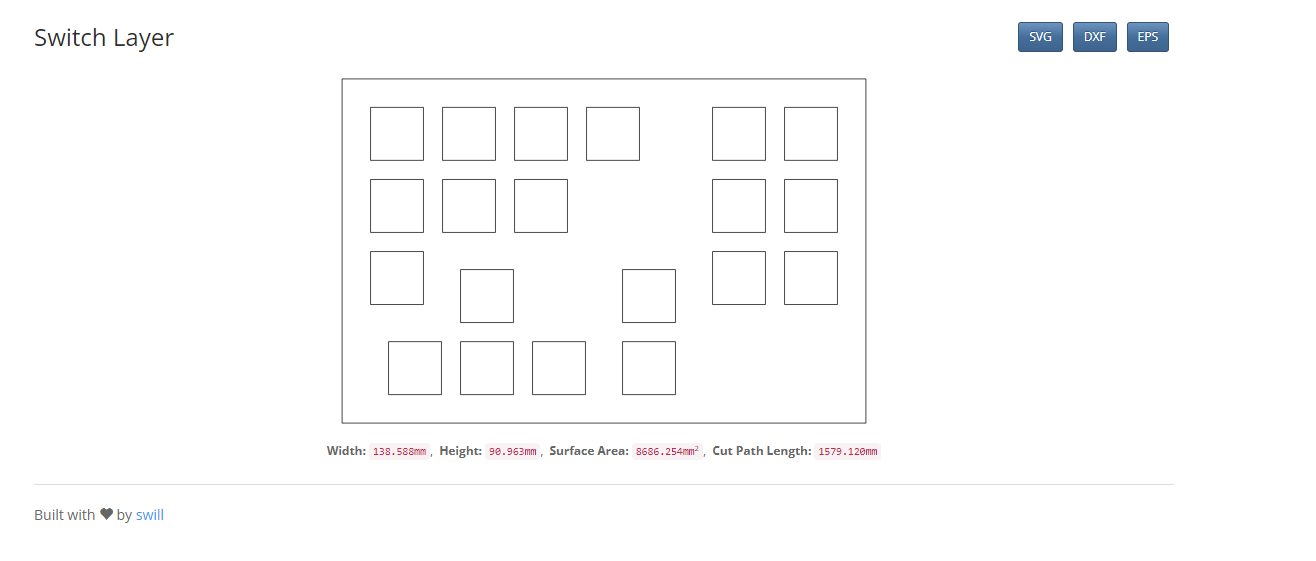
Step 2. Generate a DXF file of keyboard layout
There are some options here as you can use https://kbplate.ai03.com/ and http://builder.swillkb.com/. For this project I chose to use SWILLKB. You can copy and paste the raw data from KLE into SWILLKB. My keyboard raw data looks like this:
[{sm:"cherry",sb:"cherry",st:"MX1A-E1xx",a:6},"Home","Zero X",{sm:"",sb:"",st:""},"Zero Y",{sm:"cherry",sb:"cherry",st:"MX1A-E1xx"},"Zero Z",{x:0.75,sm:"",sb:"",st:"",f:2},"Spindle On","Spindle Off"],
[{sm:"cherry",sb:"cherry",st:"MX1A-E1xx",a:7,f:3},"Speed 1",{a:6},"Speed 2","Speed 3",{x:1.75,fa:[2]},"Change tool",{sm:"",sb:"",st:"",a:7},""],
[{sm:"cherry",sb:"cherry",st:"MX1A-E1xx",a:6,f:3},"Pause",{x:3.75,sm:"",sb:"",st:"",a:7},"",""],
[{y:-0.75,x:1.25,sm:"cherry",sb:"cherry",st:"MX1A-E1xx",a:6,f:3},"↑",{x:1.25,f:3},"Z UP"],
[{x:0.25,f:3,n:true},"←",{f:3,n:true},"↓",{f:3,n:true},"→",{x:0.25,f:3},"Z Down"]

The output can be in SVG,DXF or EPS. I chose to work in DXF format for this project as I can import it into fusion360 and KiCAD.
Step 3. Design the electronic schematics
As previously stated I will be using a ATMEGA32U4 for the brains of the keyboard. I do this because it is cheap, has lots of GPIO pins and has USB integrated. I will be using a matrix design with LL4148 diodes across the switches to give me NKRO capability. I chose to use four rows and 5 columns but you can choose any configuration of GPIO pins that you want.
I chose to use PB4, PB5, PB6, PC6, PD0, PD1, PD4, PD7 and PE6 for this project. I also added a ICSP connector so I could program the 32u4 as it does not come with a Arduino bootloader from the factory.
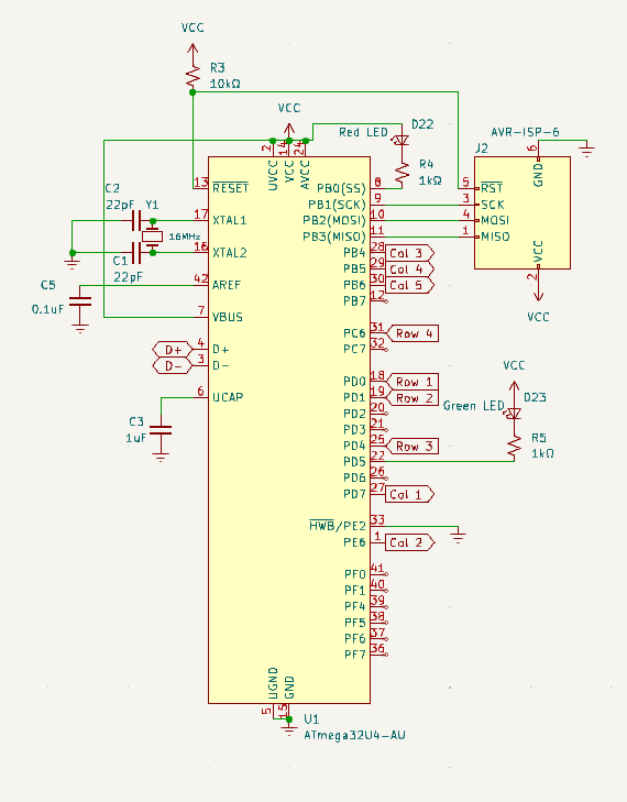
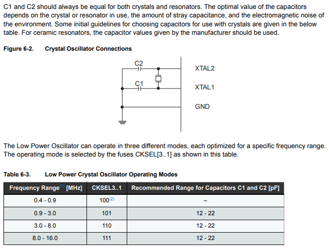
From the data sheet(https://ww1.microchip.com/downloads/en/devicedoc/atmel-7766-8-bit-avr-atmega16u4-32u4_datasheet.pdf) we can see that we need a 16MHz crystal across XTAL1 and XTAL2 with 22pF crystal load capacitors on each side of the crystal when running at 5V. I chose to run this entire project off of the USB power bus so again I referred to the data sheet and followed its recommended application.


The 32u4 has built in USB capability so D+ and D- were connected to a pad were a USB cable would be hand soldered. I made a custom footprint and symbol for this in KiCAD. 22 ohm resistors were used between the USB line and the 32u4 as called out for in the datasheet. I included a 500mA fast blow fuse on the VBUS line incase I did anything stupid as well as added a Schottky diode to prevent back flow if the device was powered by my benchtop power supply and connected to USB at the same time.

Step 4. Assign footprints and route the PCB traces
I used KiCad 7 to draw the schematics and route the PCB board. I will not go into much detail here as there are plenty of great tutorials online. The general gist of the idea is that I assigned footprints to every component in the schematic and followed general design guide lines like putting the crystal as close to the XTAL pins as possible. Capacitors as close to their connection points as possible. Impedance matched USB data lines(Doesn't matter much in my circuit as the run is very small). I imported the DXF file we previously generated as a guide when laying out the PCB to ensure proper alignment with the case.
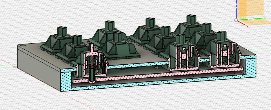
Step 5. Make the case
I exported the 3d model of my routed PCB from KiCAD and imported it into fusion360 along with the DXF file we generated earlier. 3d Models of each component was previously assigned with the footprints in step 4.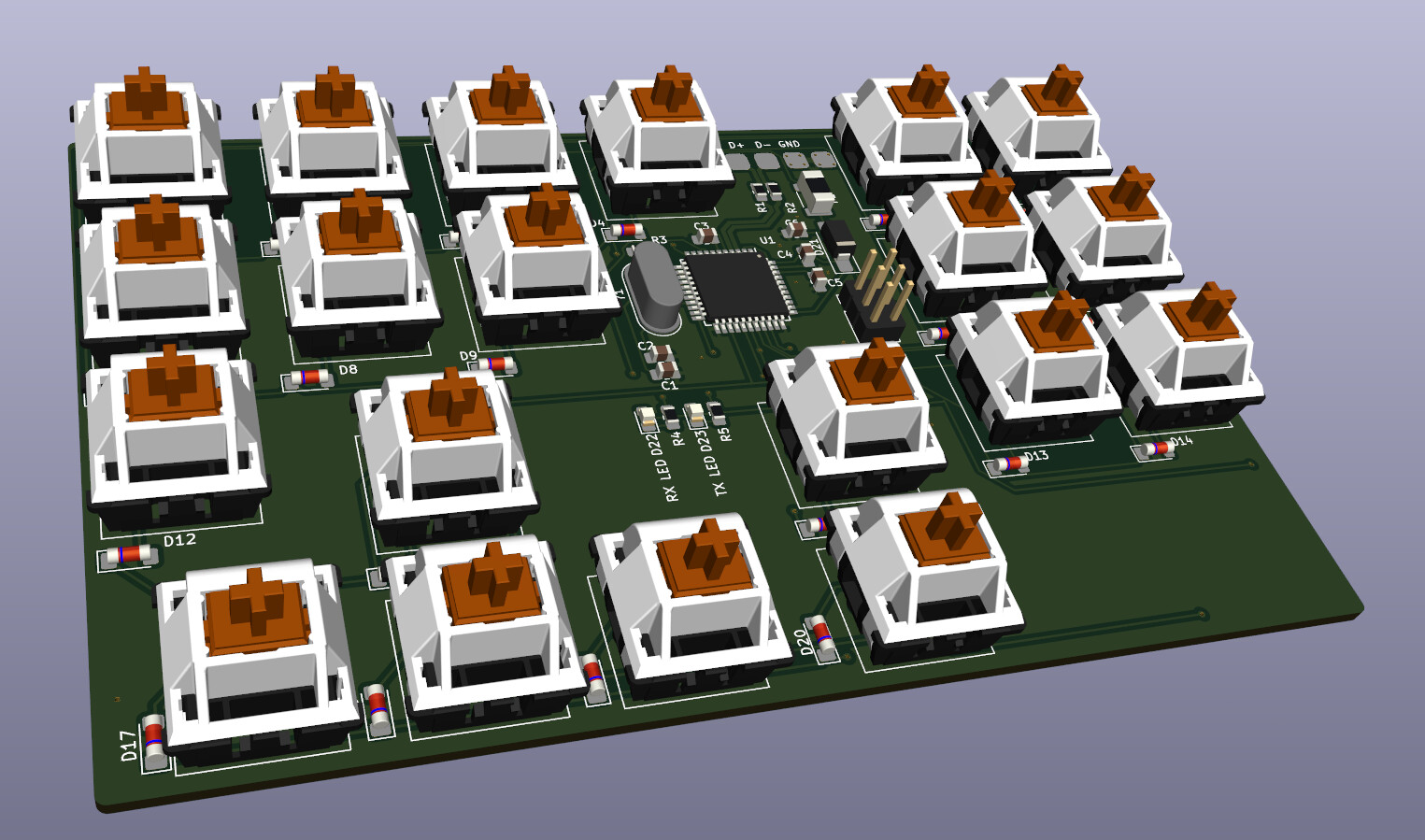
I used the DXF file to extrude the top cover and body profile needed, adding in some fillets at the same time. The 3d model exported from KiCad was used to ensure proper clearances. Once everything was modeled I used the SO5 to cut out the case from aluminum stock.
Step 6. Order the PCB
After I confirmed that the fit and alignment of the PCB and case was correct I placed a order for the PCB using JLCPCB. KiCAD was used to generate the gerber files needed.Step 7. Create Dye Sublimated Keycaps
Keycap legends were made using Adobe Illustrator. I printed out the key legends onto sublimation paper using a sublimation printer with registration marks on the page. The registration marks were used to allow my wife's silhouette cutter to accurately cut out the keycap legends(This could also be done using a shapeoko and Stingray vinyl cutter). I cut out 1/16" thick pieces of silicone that were the same size as the keycaps. The keycap legends were aligned on each key using a small amount of Elmer's adhesive spray. The keycap legends were then secured down on all four sides using Kapton tape. The 1/16" thick piece of silicone was then taped on top of the keycap legend to allow for more uniform pressure when using the heat press. I then used a heat press at 400F with light pressure for one minute and thirty seconds. The main key to success here is to have the sublimation paper firmly secured down to the keycap so that it does not lift at any time while it is hot. Failure to do so will result in ghosting and bland colors.Step 8. Soldering
I used two different techniques to solder everything. The ATMEGA32u4 along with small 0805 resistors and capacitors were soldered using solder paste and a hot air rework station. The remaining components were soldered using a normal soldering iron.Step 9. Programming
I flashed the Arduino Leonardo bootloader to the ATMEGA32u4 chip using a AVR ISP MKII, Arduino IDE and the ICSP port on the PCB. 5V power was supplied through my benchtop power supply while the flashing took place. Once this is done the board was ready to be programmed through the USB cable.The main program made use of the keyboard library to allow the board to communicate over USB as a HID keyboard with little effort. I created a custom button class to handle debouncing and special button states. The main loop just pulls each row low one at a time and then checks to see if any of the buttons are pressed in that row before pulling the row high and moving on to the next row. If it finds any buttons are pressed, it sends the key down command over USB and when it finds that button is released, it will then send a key up command.
Step 10. Assign keyboard keys to G-Sender
By far the easiest step out of them all. At this point I just plugged the keyboard into the computer and assigned each key press to the corresponding macro/jog command.
All parts can be ordered from mouser or digikey. I provided links to the main components used below. I have included all files to manufacture this your self and I also have 4 extra PCB's if anybody is interested.
Main Parts:
MX Cherry Blue Switches
PBT KeyCaps
Top plate aluminum stock
Body aluminum stock
ATMEGA32u4
LL4148 diode
keyboard-gerber.zip (149.7 KB)
keyboard-source.zip (1.3 KB)
keyboard-schematics.pdf (279.0 KB)
keyboard-kicad.zip (3.1 MB)
If you have any questions or I did not explain something clear enough please let me know.