DIY Mount Printable Version?

Got a crosshair laser I want to mount, thinking of using the diy plate space but don’t need the rigidity of an alum variant. Just want to use a model to merge my mount model onto and print it up–but I haven’t seen the base mount plate in the wild–or its hiding. :smiley:

Anyone seen one or have a schematic of it and I’ll just draft one?

1 Like

I don’t think anyone has drawn up a schematic yet.

Hang on, I’ll work one up (unofficially).

1 Like

I did this exact thing a week or so ago. I’ll try to remember to share my model of the dovetail part tonight.

4 Likes

3 Likes


Apparently I cannot attach an STL file. This was 40mm tall. I don’t recall if these dimensions were exactly what I measured with the calipers on the S5 (with dovetail fully clamped) or slightly wider since there is wiggle room to be had with a clamping mechanism.

2 Likes

Here’s a quick, unofficial, don’t ask support re-drawing:

s05pro_accessory_mount.c2d (44 KB)

2 Likes

@gsrunion & @WillAdams Much appreciated! I can easily take it from these pieces. Thank you for your contributions and time!

Oh! Since you just did this, can you share your work macro? You just dropping in an offset or anything else?

“Work macro” is not making sense to me in this context. Perhaps a term I am not familiar with?

How are you putting in your offset? I’ve seen some make user macros.

Not home at the moment. The only offset I would have added would have been to make the part slightly wider than bare minimum to give the clamping mechanism something to bit into before bottoming out. I think I did that by just manually adding a mm or so to what I measured with my calipers. I will look again when I get home to see if I can get evident of me doing that in F360.

1 Like

My apologies. I mean what are you doing for aligning your work area to the lasers offset? I hadn’t looked into that too deeply yet.

Ahh. I have not actually used it yet. I planned to do some tests to figure out the delta of the crosshairs to the actual spindle zero. Then going from there.

Since I use a fence and tend to zero from the wasteboard I don’t actually have a need to rezero the machine they often. So what I was thinking about doing was just using the crosshairs as a measurement tool to figure out where a piece resides with regard to that established zero and take that into consideration in the design….drawing a rectangle of the size of my workpiece at the measured delta + pointer offsets. Will see how that works out and if I don’t like the workflow I will add a gcode macro to move and set zero.

1 Like

Thanks again! Simple and easy. Just need to build my offset and I’ll be good to go.

1 Like

Your setup looks much more compact than mine. Can I see a picture with a little bit more lighting? I may want to emulate.

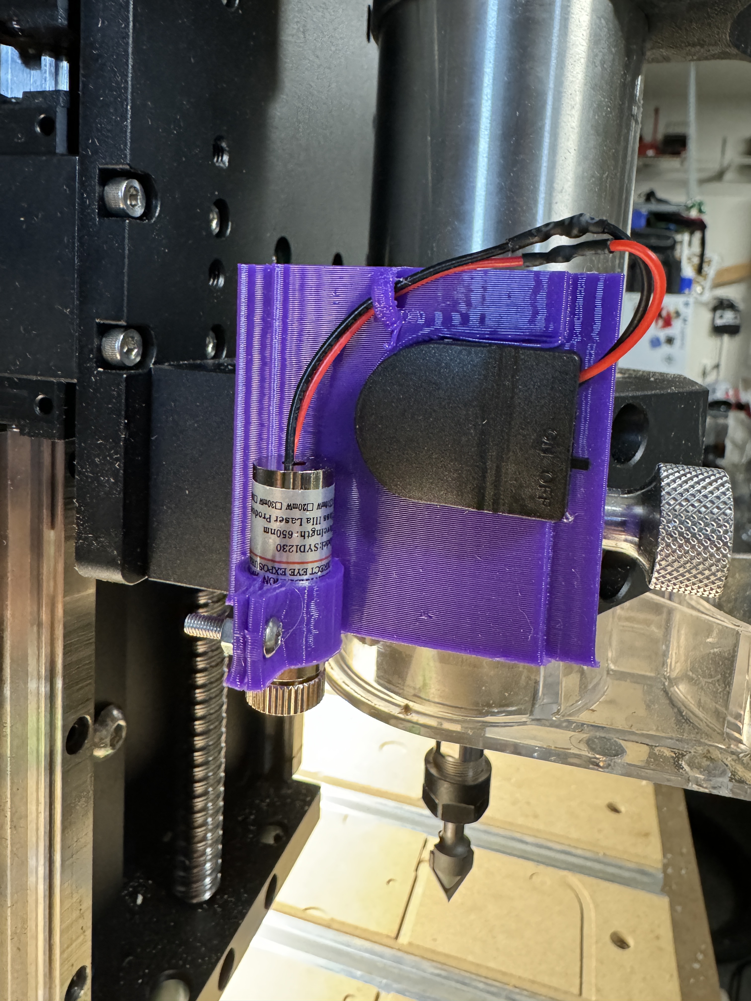
Took a laser mount someone made for the Phecda and just modified it to work with the cleat.

My offset is 3.523 x -0.440. Now to figure out how to make an action that enables or disables the offset.

I see some work was made here : CM Work offset? but I don’t see a final working method.

Only caveat I just saw is my screws will catch if you are at the rapid front-left. So need to be aware of doing full carves or just using front left as a zero point. Might be able to make it a little lower profile in the future. Always something! :smiley:

I like this design more than what I came up with and gives me ideas. I’ll model something up in a day or two.

1 Like

This topic was automatically closed 30 days after the last reply. New replies are no longer allowed.