CM Work offset?

I asked this a year ago with no response.

Does CM use any work offsets? Or is it stored/calculated in software?

I was using gSender for a while to have simple macros to offset my zero for my laser. With quick actions in CM now, I could add a macro to adjust the work offset for my laser.

CM uses G54 by default. Machine coordinate moves need a G53 (non-modal) on each line using G53.
CM doesn’t support G55-59. However, other G-Code senders do.
Not sure what would happen if you sent a program with G55-59 through CM. To circumvent CM pre-processing the command, a backslash may be needed \G55 X… Y… Z…

GRBL does support G53 - G59

Supported G-Codes in v1.1

  • G54, G55, G56, G57, G58, G59: Work Coordinate Systems
2 Likes

Ooof. I might stick with gSender in that case.

1 Like

Work offsets via quick actions serve the same purpose, and make it easier to keep them by name, rather than number.

2 Likes

Any time you “set zero”, you’re establishing a new work offset.
@greg5 Can you explain exactly what you’re trying to do?

Spindle is at 0,0. Laser is at some arbitrary offset relative to that position, X-100, Y-50.

gSender setup

  • Setup workpiece origin
  • Hit macro button which will adjust by X-100Y-50, set this as new origin.
  • Toggle GRBL laser mode, run laser gcode
  • Toggle GRBL laser mode off
  • Run macro that will adjust X+100Y+50, set as new origin
  • Run gcode to cutout the piece

G10L20X0Y0

G10L20X-150Y-50 (assuming laser is 150 left and 50 back from end mill)

Move back to X-150Y-50 (your original 0,0), and reset Work origin here
G10L20X0Y0

No need to use the other Work Coordinate Systems (G55-G59) in this case.

1 Like

Nice! So I could make these as quick actions and Carbide Motion would not touch these when running files? Or it will pickup these new homes in the GUI? (For deactivate, I can just invert your logic a bit?)

Activate laser mode

G0 X0 Y0
G10L20X-150Y-50
G0 X0 Y0

Deactivate laser mode

G0 X0 Y0
G10L20X150Y50
G0 X0 Y0

image

Just gave it a shot today, I was using gSender previously. No luck with quick actions.

Here’s my "spindle to laser macro - X/Y values are measured now, above were just examples.

G0 X0 Y0 F3000
G0 X110.6 Y-23.6 F500
G54
G10 L20 X0Y0

That’s a Motion thing. By default, the workspace is G54 which is P1.
Add a P1 after the G10L20

Nice, that did it for the most part. Having issues with CM picking up the new values afterwards. The GUI still shows the values X110.6Y-23.6.

You’re sending /G10L20P1X0Y0 ?

1 Like

This was via quick-actions - do I need to escape with a / or is that MDI only?

1 Like

I’d assume without, but I have no idea.

If you successfully send it to the controller and tie with offsets don’t change, my only guess would be that you’re in a different WCS for some reason.

Maybe @robgrz can chime in.

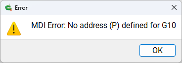
It could be that CM detects the G0 commands, but not the G10. So the UI shows the last XY which was X110.6 Y-23.6. I’ll hop to the garage later today maybe if I use CM to jog once it’ll instantly pick up the new position.

gSender has this “laser offset” built in as a feature.

I’m using Vcarve Pro with @wb9tpg Gary’s mod of the post processor which adds the laser offset to the gCode.

Perhaps CM could add the offset as a feature?

Well aware of that :slight_smile: It’s great in gSender. Their tool-change is lacking, but there’s some recent work in the EDGE builds which is promising. The stability of gSender isn’t great right now.

You don’t need multiple coordinate systems to accomplish this (ie: g54, g55, etc). You can do it all with the G92 command. Easy peasy

1 Like

I don’t think @greg5 is trying to use multiple WCSs.
Also, welcome back @wb9tpg.

This topic was automatically closed 30 days after the last reply. New replies are no longer allowed.