this is what’s coming out before the double sided tape way. Still have not tried those methods.
I have tried paper method and that worked. I think that worked but wanted to not have to go paper method every time and tried different things like probing Z with 90 v bit with 201 end mill selected.
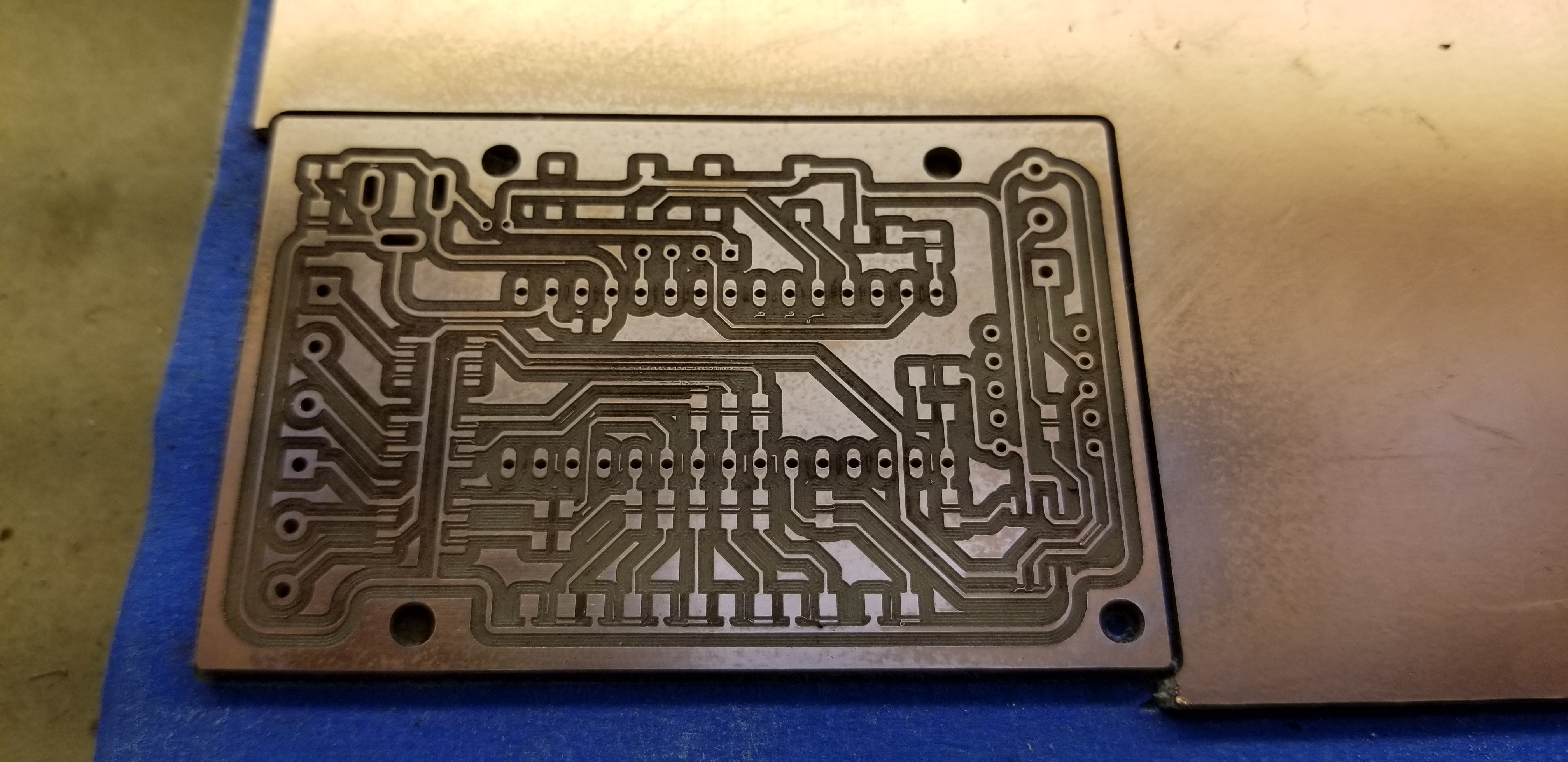
Left side of stock (right side when engraving) is deeper into the stock vs the other side. would like to get past this hurdle if possible!! Thanks for all the help!
for the residual left/right difference in depth, what you could do before cutting is manually jog down to the stock surface, touch off using the paper method, make a note of the current Z value there, and then repeat that at various places across the stock surface (at least one measurement on the left side, and one on the right side).
If you see differences in Z values between the left and right sides of the stock, it will at least confirm that this is why you get differences in cut depth. And since surfacing the stock is not an option here, a poor man’s autoleveling could be to just shim one side by inserting a piece of paper under the left/right half of the stock(or two, or three…) and recheck Z value at stock surface. It’s still bound to be time consuming though.
Wouldn’t placing shims under one side create a gap just next to it and create a spot for sag to happen though?
the surface is flat and the acrylic sheets are a certain thickness so I don’t believe the stock has different heights between multiple spots. will check that tho next time! Thanks for the help by the way!
@MindlessCorpse is right, check that your table surface is parallel with your spindle carriage by mounting a dial indicator to it and moving it around.
As for acrylic being different thicknesses in different spots… acrylic is notorious for this. For most applications it doesn’t matter but it may in your case. You can check this after you verify your table surface with the same setup.
You could use the method described by @Julien above.
Use the shapeoko z-axis with a piece of paper. Run a bit down until it just gives you a bit of a tug on the paper, note the z value on your screen and move to different areas and repeat, hoping for the same value.
Good Luck.
edit… for as small of a sample as you are trying, I would use an engraving bit to carve that, also, fwiw, the shapeoko can be Very Accurate.
Anyone know why it goes and digs into the stock and took 4 attempts of the same g code to get the proper depth? pullys are tight and set screw is on the flat spot.