WillAdams
August 20, 2020, 12:20am
1
This has been a topic of discussion on the OpenSCAD mailing list and Reddit and to a degree here.
Put up a survey 'cause I was curious:
and will put the results up at:
https://wiki.shapeoko.com/index.php/OpenSCAD#CAM_options_for_OpenSCAD
As noted there there are a couple of options for CAM in OpenSCAD:
export an STL
export a DXF or SVG
import into FreeCAD
program in parallel
use some sort of direct CAM interface
It’s that last which we will examine here, working up a basic test file for an endmill geometry which is not supported by Carbide Create, a tapered ball endmill:
https://www.amazon.com/gp/product/B086V9RW8C
Weeker ZQ21A3 CNC Router Bits 2D&3D Carving 3.6 Deg Tapered Angle 2 Flute Ball Nose 1/4" Shank 1/16"X1 1/2"X1/4"X3’
The BlockSCAD version is available at:
https://www.blockscad3d.com/community/projects/964669
and the OpenSCAD code may be easily exported from it.
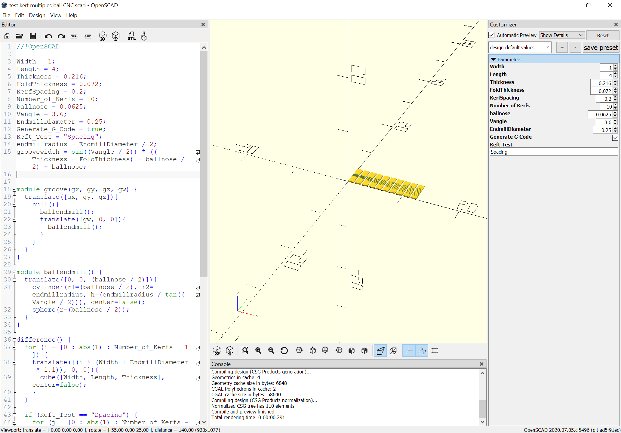
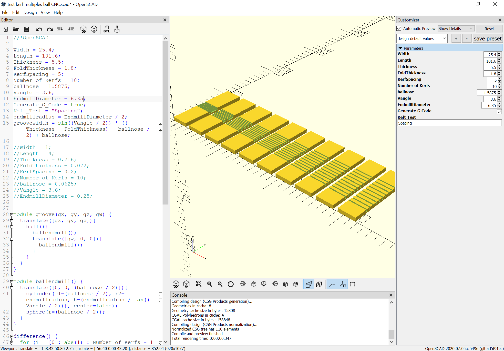
As has been discussed in the past, the first thing to do is to move the variables to the top of the file so that they will work with the Customizer:
and then updating them to reflect the metric default in OpenCAD.
WillAdams
August 20, 2020, 12:48am
2
One notable consideration here was avoiding the use of transform() so as to ensure that the cuts in question would all be done in the same coordinate space when written out as G-Code:
the module used for the cutting has as arguments the begin/end points, so it is a simple matter of writing them out suitably.
First, add a section for the CAM settings (moving appropriate variables there and adding those necessary):
/* [CAM settings] */
ballnose = 1.5875;
Vangle = 3.6;
EndmillDiameter = 6.35;
feedrate = 600;
plungerate = 150;
safeheight = 8;
Then we add the appropriate commands to export the G-Code:
echo(str("G0 X",gx," Y",gy," Z",safeheight));
echo(str("G1 Z",gz," F",plungerate));
echo(str("G1 X",gx + gw," Y",gy," F",feedrate));
echo(str("G0 Z",safeheight));
which results in the G-Code being written out to the Console:
ECHO: "G0 X0 Y42.4061 Z8"
ECHO: "G1 Z1.8 F150"
ECHO: "G1 X25.4 Y42.4061 F600"
ECHO: "G0 Z8"
ECHO: "G0 X0 Y44.0848 Z8"
ECHO: "G1 Z1.8 F150"
We do need to work out adding a suitable preamble and postamble.
WillAdams
August 20, 2020, 1:10am
3
The commands needed for the preamble are roughly:
G90
G21
M05
M6T140
M03S10000
which indicate that we need to go back and add a few more variables:
Endmill_Number = 21;
speed = 18000;
and simply add the suitable commands after the variable declarations:
echo(str("G90"));
echo(str("G21"));
echo(str("M05"));
echo(str("M6T",Endmill_Number));
echo(str("M03S",speed));
Similarly, we add the postamble at the end of the file:
echo(str("M02"));
For anyone curious, the file is here:
test kerf multiples ball CNC.zip (989 Bytes)
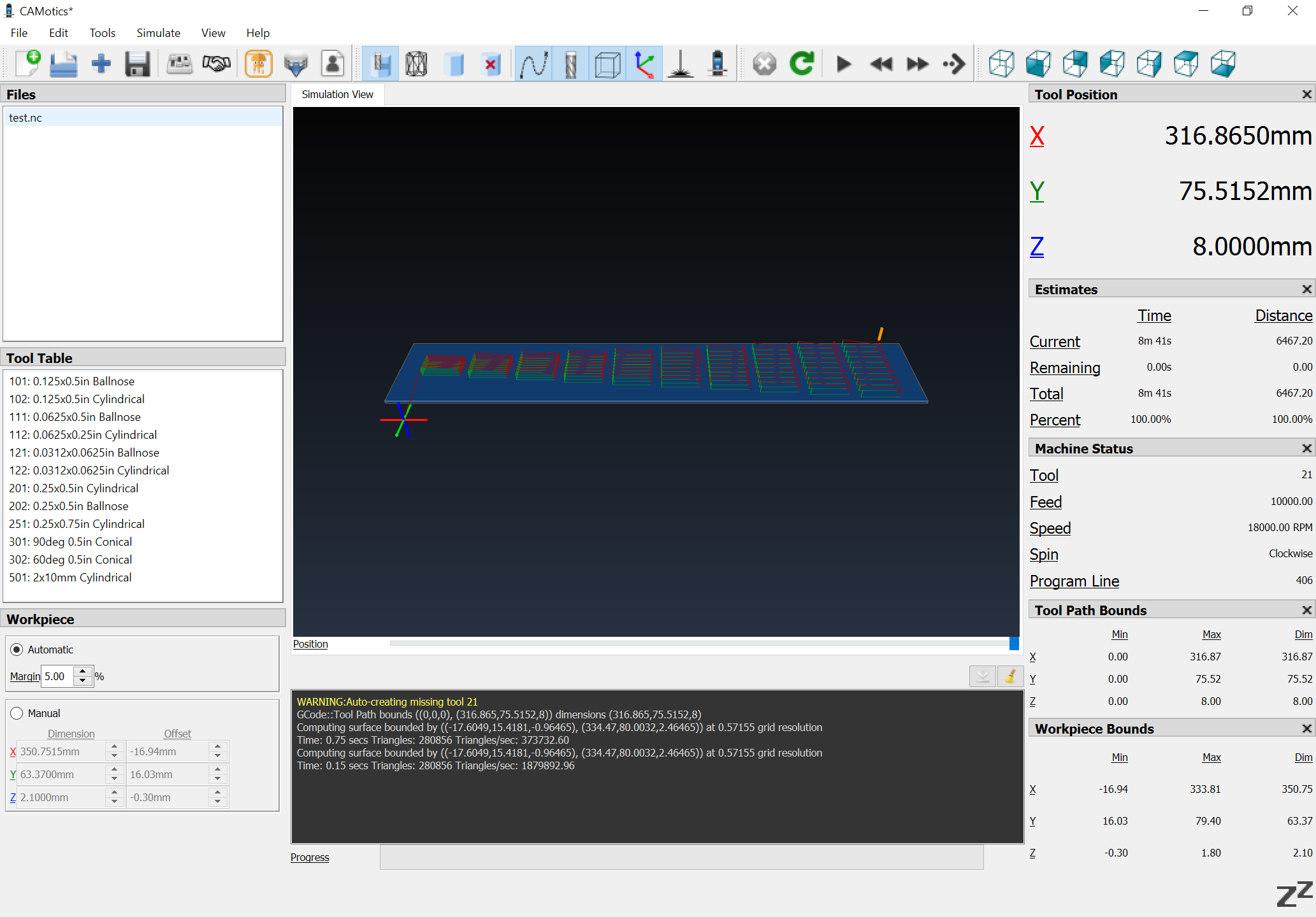
Copying the console text and editing it appropriately gets one a file which previews as expected:
One concern is the cutting is done at full depth, and the test parts are not being cut out, but the former is easily addressed with a suitable loop, and the latter by modifying the file so that a DXF may be exported, or doing the geometry to move the endmill around the parts as necessary.
WillAdams
August 21, 2020, 2:18am
4
To make multiple passes it’s a simple matter of variables to support it and the necessary calculations:
Depth_per_Pass = 0.5;

numpasses = round((Thickness / FoldThickness)/Depth_per_Pass+0.5);
cutdepthperpass = (Thickness / FoldThickness)/numpasses;
and adding a loop:
for (i = [1 : abs(1) : numpasses]) {
    echo(str("G1 X",gx + gw," Y",gy," Z",Thickness-(i*cutdepthperpass)," F",feedrate));
    echo(str("G1 X",gx," Y",gy));
}
(while we’re at it we’ll experiment with ramped cuts)
WillAdams
August 23, 2020, 4:36pm
5
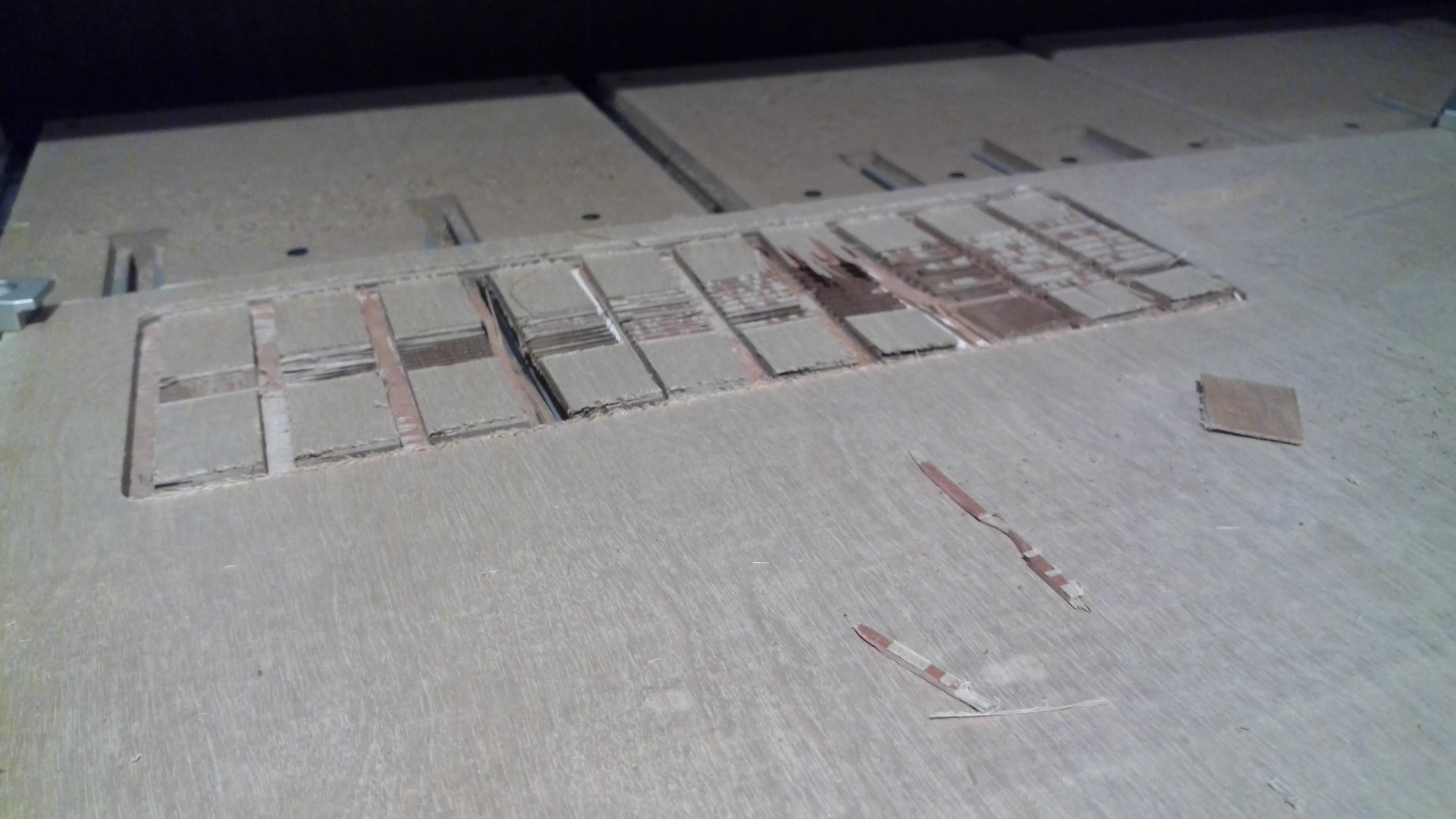
Test cut worked, but is a reminder grain direction matters even in plywood:
(and apparently the top layer is ~0.18mm thick — should be able to do something w/ that)
Next up is cutting the parts out with a file exported from OpenSCAD and for which CAM was done in Carbide Create and should be in register.
This is interesting but I have to ask: why? It seems to me the main motivation here would have to be manually controlling your toolpaths in a way that other CAM tools don’t allow. Do you have plans for a custom machining strategy that doesn’t exist in Fusion 360 or something like that?
WillAdams
August 23, 2020, 5:09pm
7
Yes, I want to use tools which traditional CAM tools don’t support (e.g., radiusing endmills) and to do toolpaths which aren’t easily done using traditional CAM tools (mostly for joinery — I’ve got plans for a blind miter joint with hidden spline and some other designs).
Unfortunately, the actual cutting didn’t work out as well as the toolpaths:
On to another test.
2 Likes
Hmm, is it not possible to set up arbitrary mills in Fusion as form mills?
Not here to challenge you or anything, just wondering if there’s another way if I run into this myself one day.
WillAdams
August 23, 2020, 5:30pm
9
No interest in using Autodesk stuff — my liver wouldn’t be able to take the drinking I’d have to do to put up with them again.
I’ve been considering OnShape, but still leary of them given the bait and switch of their free license change.
I’d rather just do it all in open source — once I’ve got a complete workflow I’ll investigate other tools, some possibilities:
BRL-CAD — a venerable tool from the U.S. Army it’s gained some traction recently and the website got quite a fix
FreeCAD — it’s possible to open OpenSCAD files in it, and the Path Workbench is apparently improving quite a bit
Maker.js and Openjscad
WillAdams
September 19, 2020, 12:20am
10
This topic was automatically closed after 30 days. New replies are no longer allowed.
WillAdams
July 5, 2021, 8:35pm
12
A notable limitation here is that OpenSCAD limits the Console Log to 5,000 lines.