Ok, I would like to do some inlays on this chessboard. Some of the squares have a design in them and the others are blank. Those blank squares is what I would like to place the inlays in, just a contrast color of wood. I have no idea how to do that within a 3D file. I’m using a MacBook Pro and Vectric is not compatible. I’m using Carbide Create Pro Build 764. Any help will be appreciated.
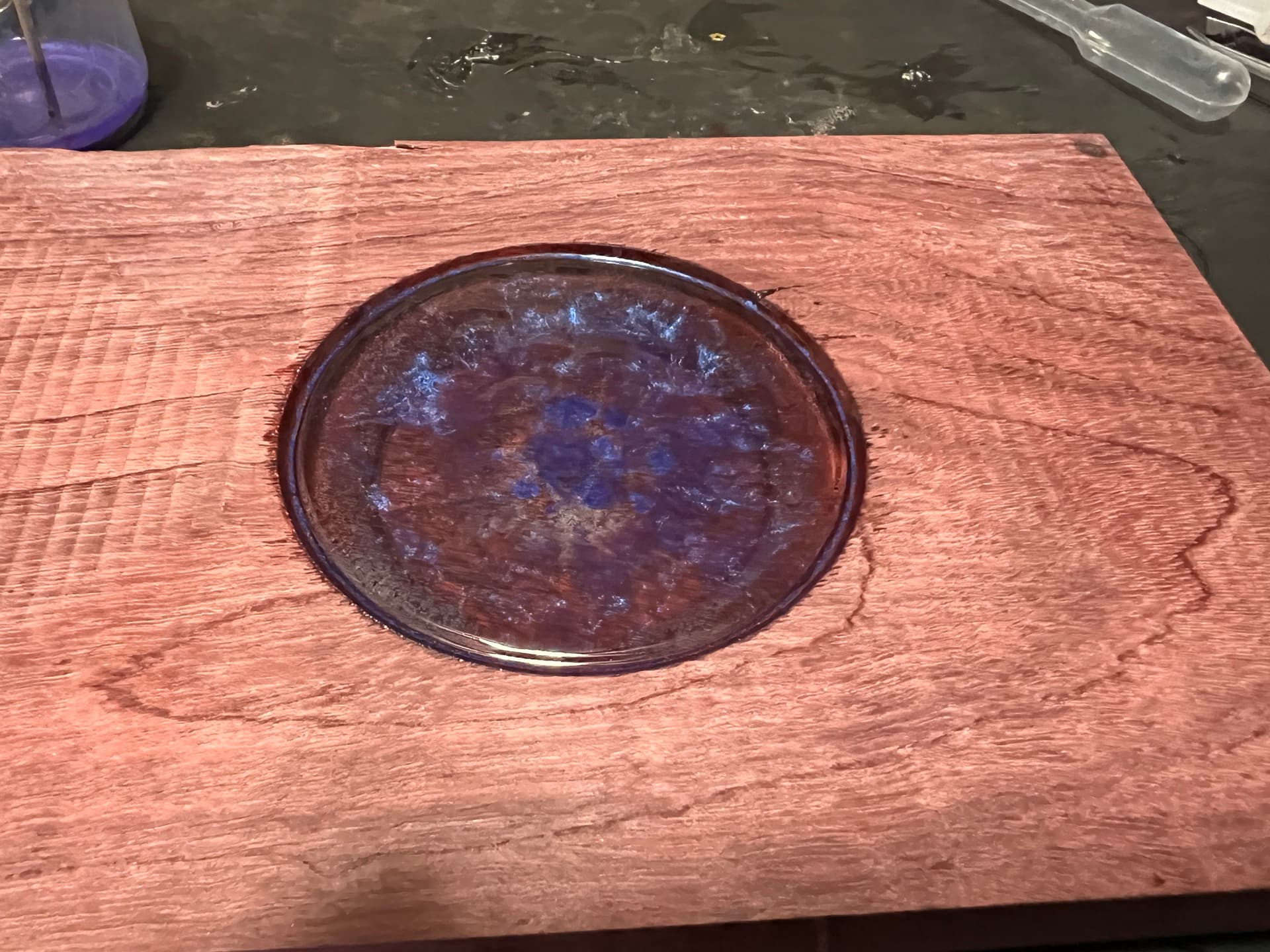
If the area you want the resin located is part of your 3D design, one method I’ve used is to first cut pockets where the resin is desired, then pour the resin. (AKA Cut-Resin-Cut).
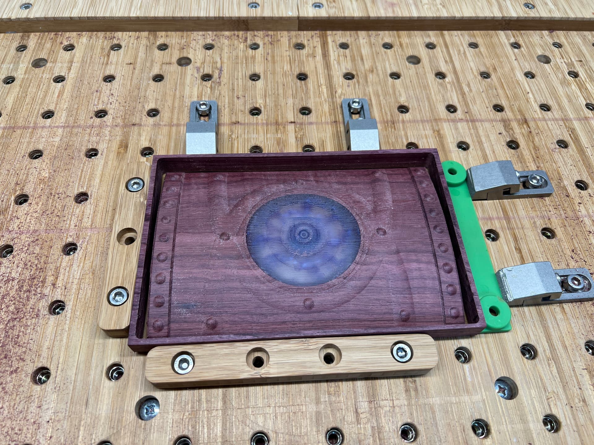
You essentially need to set the inlay deeper than the 3D cut, so that when you come back over to do the 3D passes you don’t remove the inlay.
So if the max depth of your 3d cut is 0.5" for example, then cut your inlays to be 0.6", then when you do the 3D passes, you would still have 0.1" of inlay left in the piece. Obviously it’s going to depend on the bit you are using and the level of detail needed for the inlay, but hopefully you get the idea.
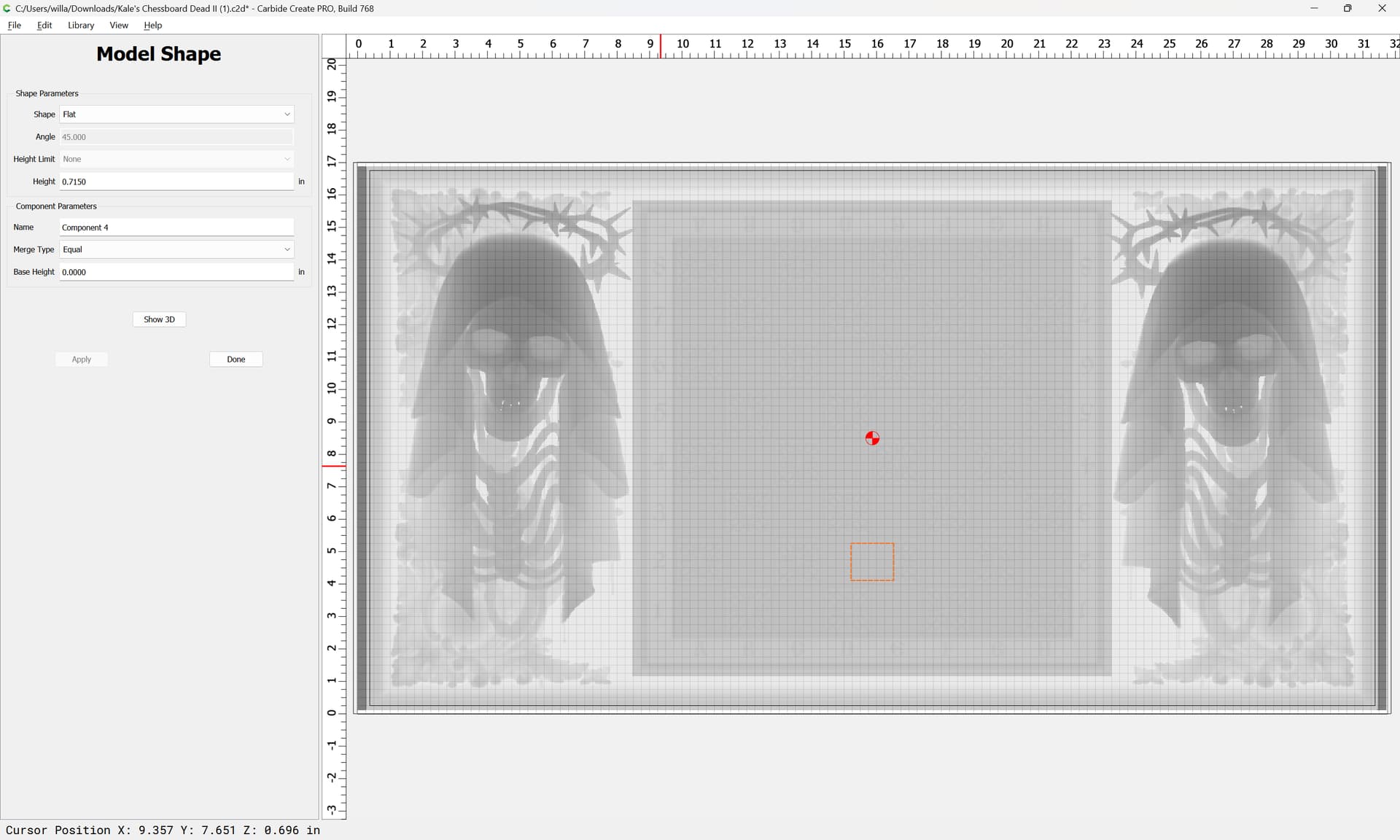
Thanks for all of your suggestions, but in Carbide create I’m unable to actually see the squares once the 3D toolpaths are created. I can see them in the modeling section, but nowhere else. If I could see them, then I believe that I could figure out the toolpaths. Any advice?
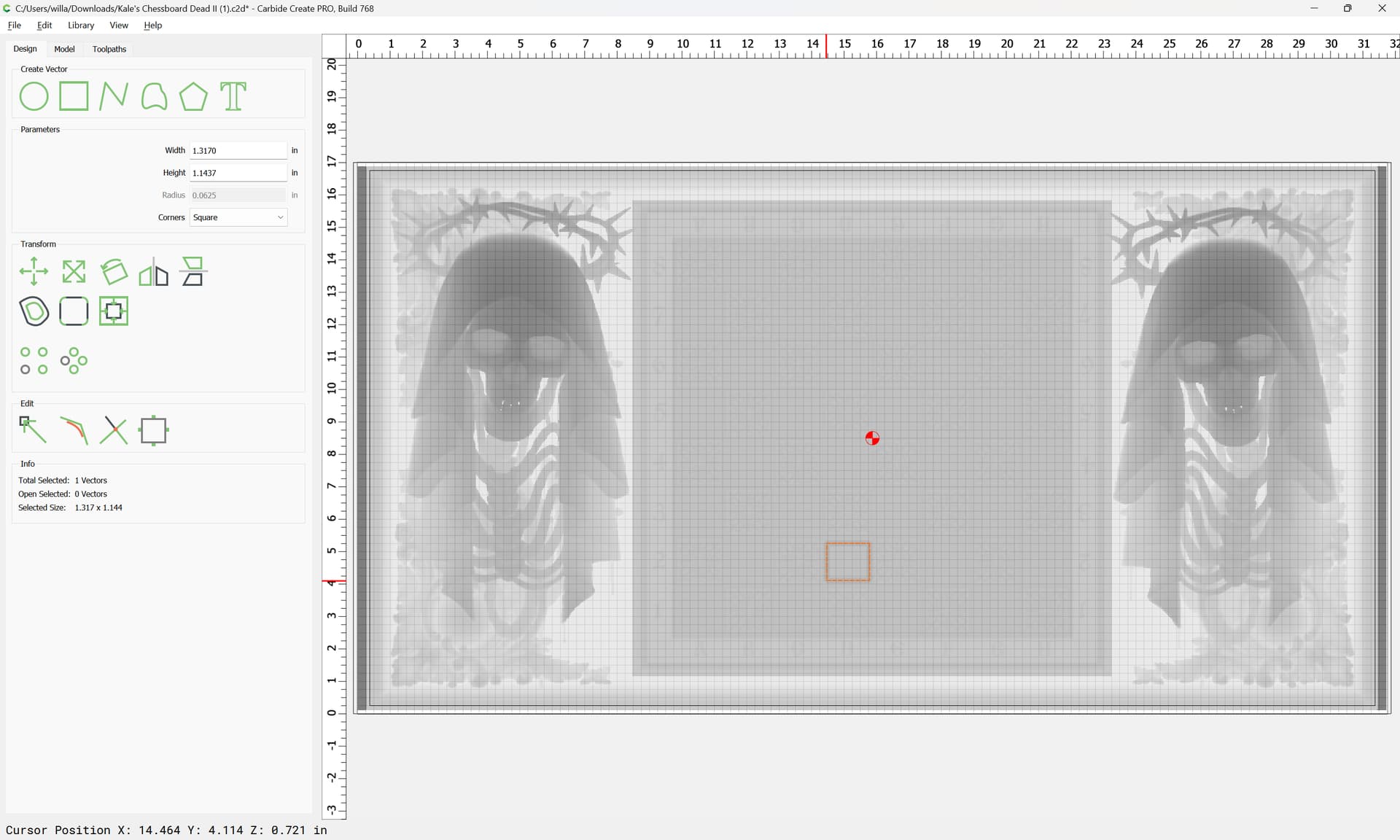
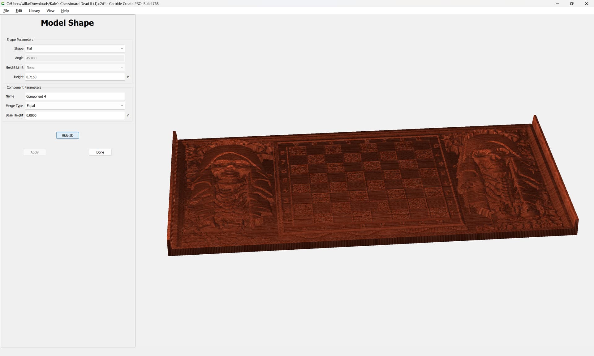
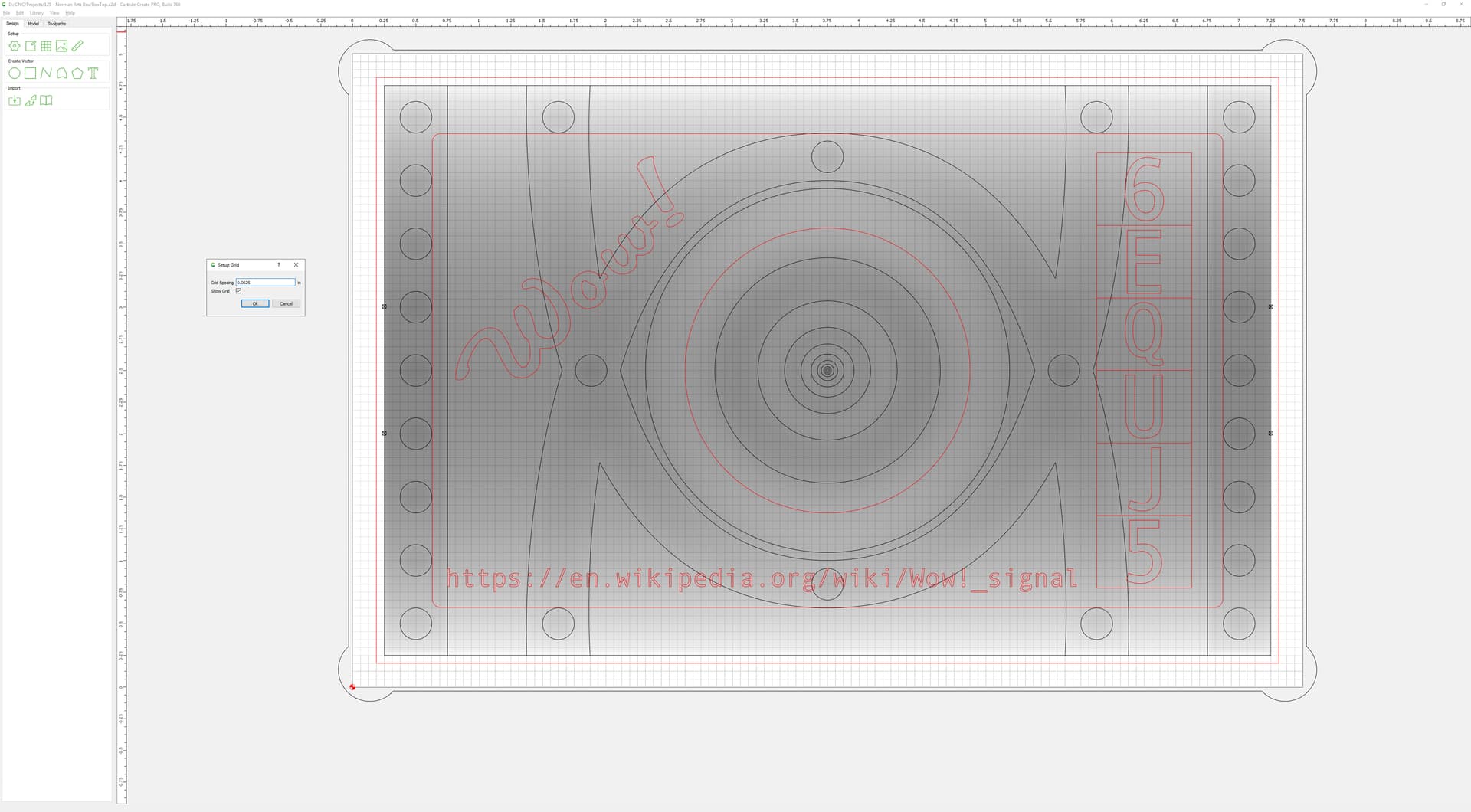
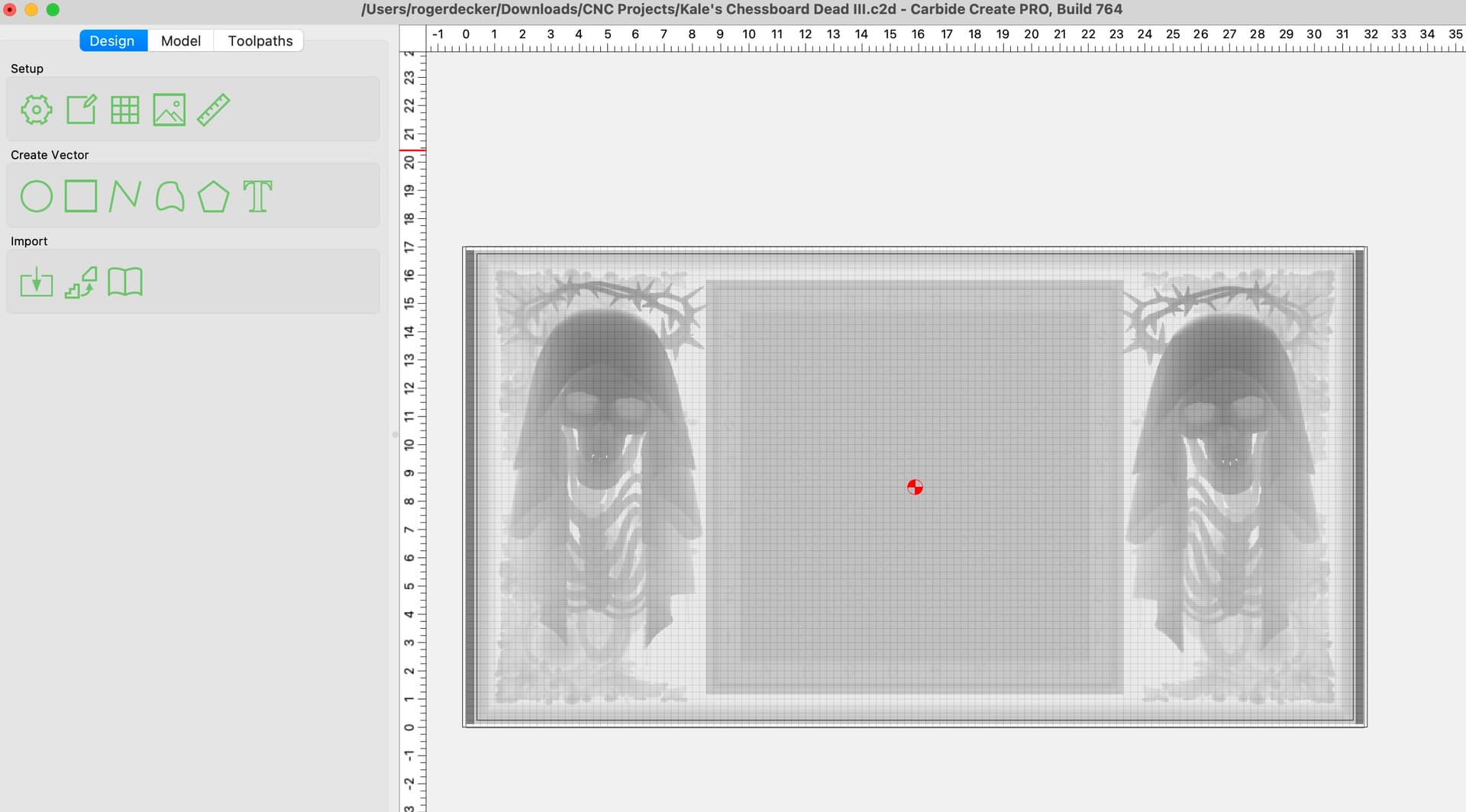
Not sure I understand, here is what my project looked like in Carbide Create.
I’m assuming the higher (darker) areas on your model must be roughly the same shade of gray they use for the grid?
Right. I showed drawing in a rectangle so as to determine the Z-axis depth using an Equal 3D model — with a good quality display you can see the various squares, or you can just set the rectangle and adjust its size/position as necessary to determine where each square is.
Oh sorry, when you said “squares” I thought you were talking about the Carbide Create grid. Now I understand you are talking about the chess squares. And since they are the same height, yea they have the same gray color.