Yep, I know and agree that it is much simpler and more efficient to just cut a part, measure, adjust, and repeat. This is all just an exercize in figuring out by myself whether there’s hope for a more predictive/deterministic approach, that would not require re-cutting parts multiples times (at least 2) to get to spot on dimensions.
1 Like
I have the steel belts, in fact, not the stock belts anymore. So what would have been REALLY interesting, is doing all of this BEFORE I changed the belts, redo it after, and compare. But I’m not willing to change back to the stock belts just for this test. It may just mean that the steel belts are excellent, and do not stretch beyond the 0.02mm figure I see, which in all honesty is pretty good and does not need further work.
1 Like
ok, don’t mind me, I’m just using this thread to keep notes on the progress.
Tonight was a good step, I fully automated the data capture process:
- wrote a small Python script that generates the G-code to make hundreds of movemements.
- each step consists in
G1F2000.000000
G4P0.5
M3S10000
G4P0.1
M5
G4P1.0
so basically, go to a new position, wait half a sec then activate the PWM signal, which I use as a trigger to tell the other arduino to acquire data from the DRO.
I also reset the DRO between each position, by having the arduino turn off/turn on its 1.5V supply. This way I start each move at 0.000 readout, and do not accumulate DRO errors. This is done by the arduino, and in the meantime the G-code waits a bit (1sec)
Got 1000 data points tonight. Proof of concept complete, now I’ll focus on rebuilding a more precise/stiff frame.
1 Like
you wild Julien
the only thing that comes to mind is in regards to the linear rails to the wasteboard (mdf?)
temperature humidity and resting weight on the board could impact your results.
id pull data as fast as possible without touching any part of it.
account for some tolerance given your setup in its current state. really dig this btw!
2 Likes
Just for everyone’s reference - Foundations of Mechanical Accuracy is available here:
2 Likes
Wow, thanks for the link.
Yep, this MDF-based nonsense was just to have something setup quickly to find out if anything else would not work out (e.g. the electronic part), but this is definitely why I’m after building a more serious frame for the DRO now. That and resetting the DRO between each measurement will (hopefully) get me closer to something useful.
1 Like
ah, my mistake overlooked it mentioned previously.
so mostly this will just be a nice DRO readout for now with the stock hardware?
It would be slick to incorporate a Z probe then you’d have some surface mapping as well.
a macro for a program and you’d have the topology of your bed/surface fixture/part.
BLtouch from 3d printer world comes to mind.
just thinking out loud.
2 Likes
Absolutely. I love the bed leveling/calibration feature on my 3d printer and it would be useful to have that on the Shapeoko. People doing PCBs with the shapeoko/nomad can do this already, but it is sender-dependent.
On the Shapeoko the bed leveling is not super useful as we can surface the wasteboard anyway, but a Z mapping would help compensating potential inacurracies of the Z axis itself. Since I have the HDZ this is lowest on my priority list though.
1 Like
Work in progress of prototype #1.0, the two-axis 8020-based version.
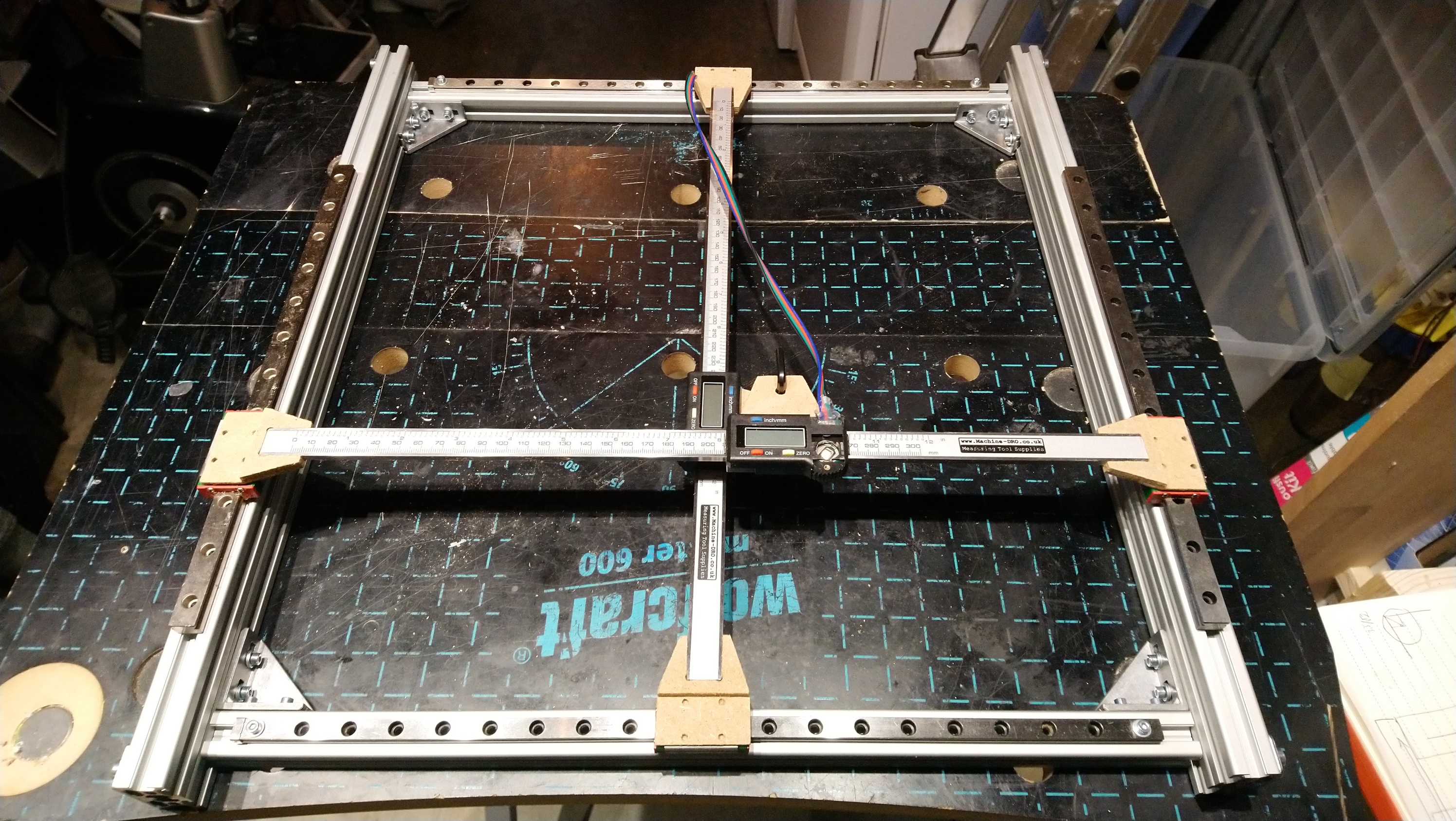
I prototyped the DRO fixturing pieces out of MDF just to verify dimensions and clearance, now I need to receive the Aluminium stock I ordered and cut them for real. Then square and tighten the whole thing.
I need to be careful or I’ll end-up building a shapeoko to calibrate a shapeoko 
6 Likes
Holy smokes, this is a very interesting thread and I’m learning quite a bit.
1 Like
Minor progress this week-end, I cut 4 of these:
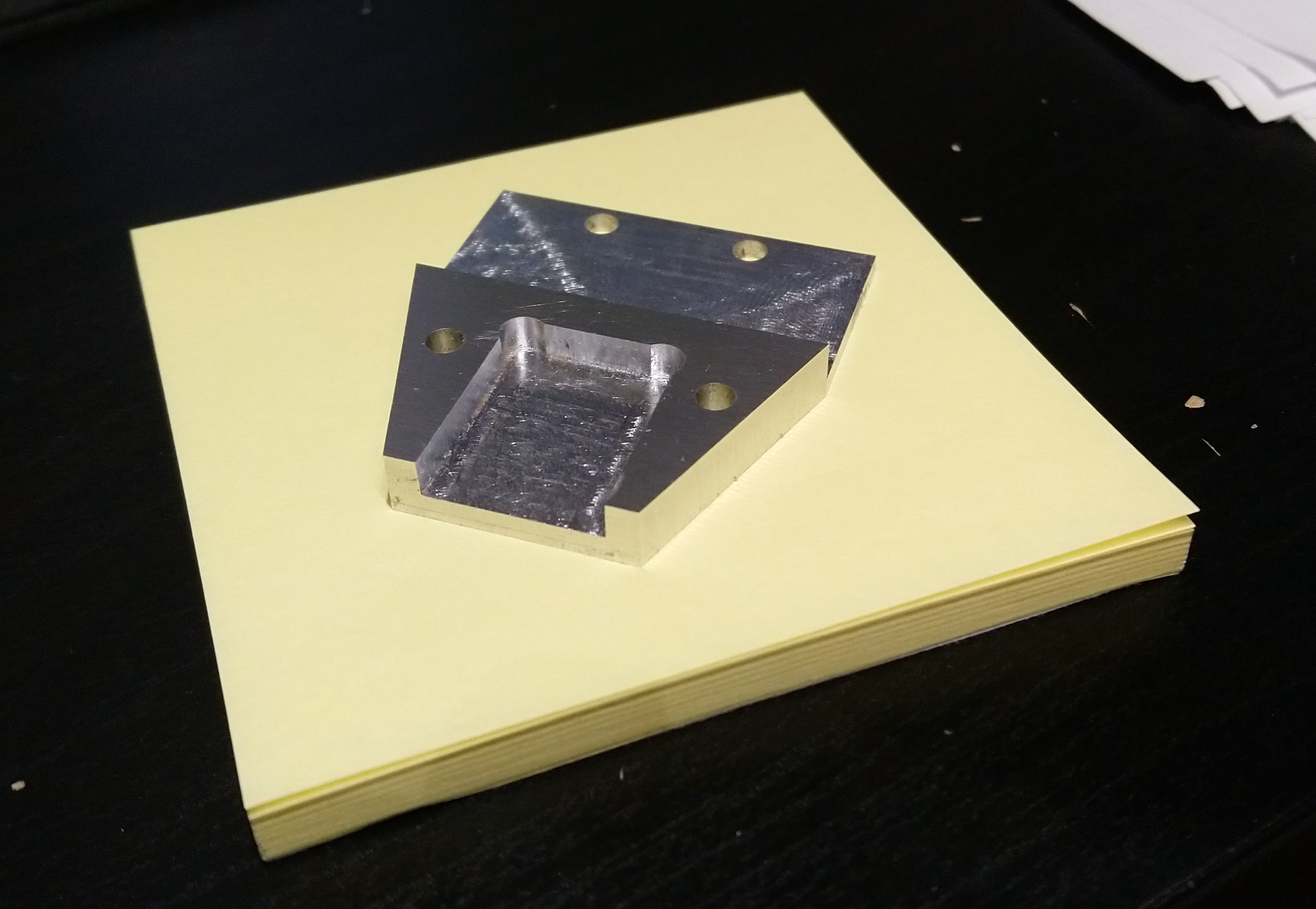
By the way, I’m now addicted to that sweet sweet adaptive cut sound !
3 Likes
Heck yeah, what a great sound. I dislike hearing slotting anymore and try to use adaptive as much as possible.
1 Like
Prototype V1 completed
Now working on the Python toolpath generator to grab interesting data and see where this leads me.
7 Likes
So last night I generated and ran a G-code file that goes to a random X/Y location, moves by a random distance chosen between 10 and 50mm along either positive X, negative X, positive Y, or negative Y, and repeats this 500 times, while the arduino captures the actual distance seen by the DROs.
Plotting the error gave me this:
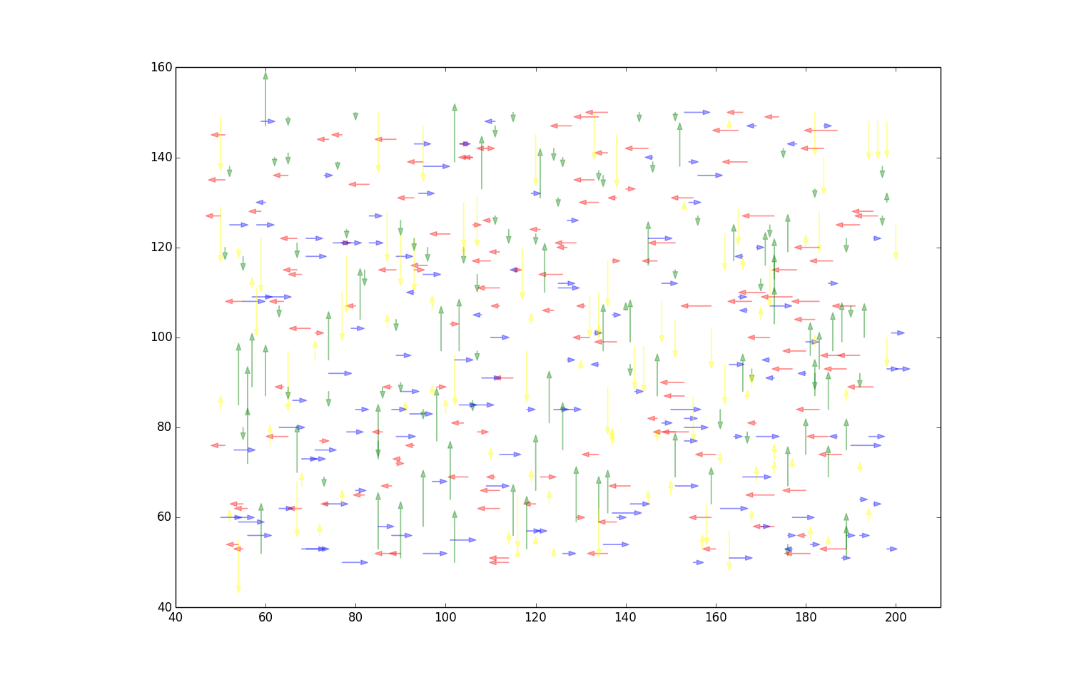
(errors range from -0.1mm to about +0.5mm)
No big surprise, I’m seeing the inaccuracies of my setup, not the Shapeoko’s (which I know by experience are below 0.1 mm on my machine). But it makes for a fun picture.
Before I give up on this, I’ll try a run with a few tens of thousands sample points, which hopefully will average out the setup inaccuracies, and provides a map of the error along each direction at each point of the workspace.
My mechanical design skills are just not good enough to build a setup that is more precise than the Shapeoko itself. Now I daydream about some other non-mechanical measurement system for this…
5 Likes
I’ve like you to come around and have a go on mine
2 Likes
A super accurate laser measure that sits in the router mount?
1 Like
Do not tempt me sir
I am now considering using a laser indeed, and a scanner readout bar or whatever they are called, these things are cheap and resolution is very decent. Or maybe I’ll stop the crazyness instead!
1 Like
What about a high precision optical mouse or something similar?
2 Likes
I’m just waiting until someone starts using a mic to auto adjust speeds and feeds…
1 Like