There was a recent bit on reddit about using machine vibration to calibrate things.
My understanding was the Lobo CNC used spare parts from PS2 joysticks for positional encoding and when that parts availability dried up became untenable.
I really think the next two big hobby CNC developments will be something using sensors, and something else using a 4th axis.
I think you are onto something. 5min of googling brought me to this:
Now I HAVE to try something like that, which if it provides reliable data would be vastly superior to my complicated mechanical setup. Probably cannot be used for absolute/long term positioning feedback, but hovering this over the wasteboard and measuring relative moves in the neighbourhood of each point could work. And then I would add a distance finder to map the Z height across the wasteboard. Oh my, what have you done, I am getting carried away again…
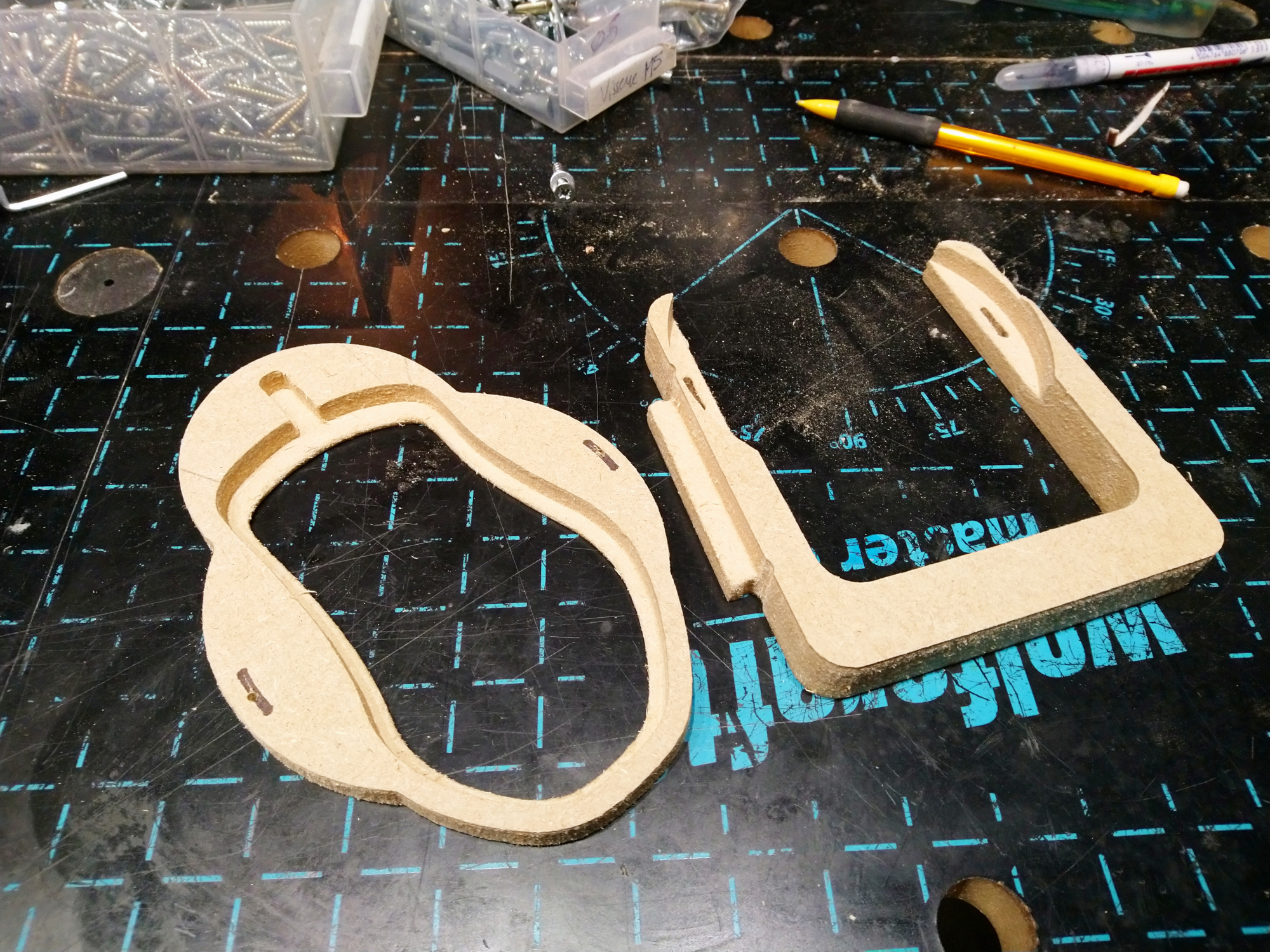
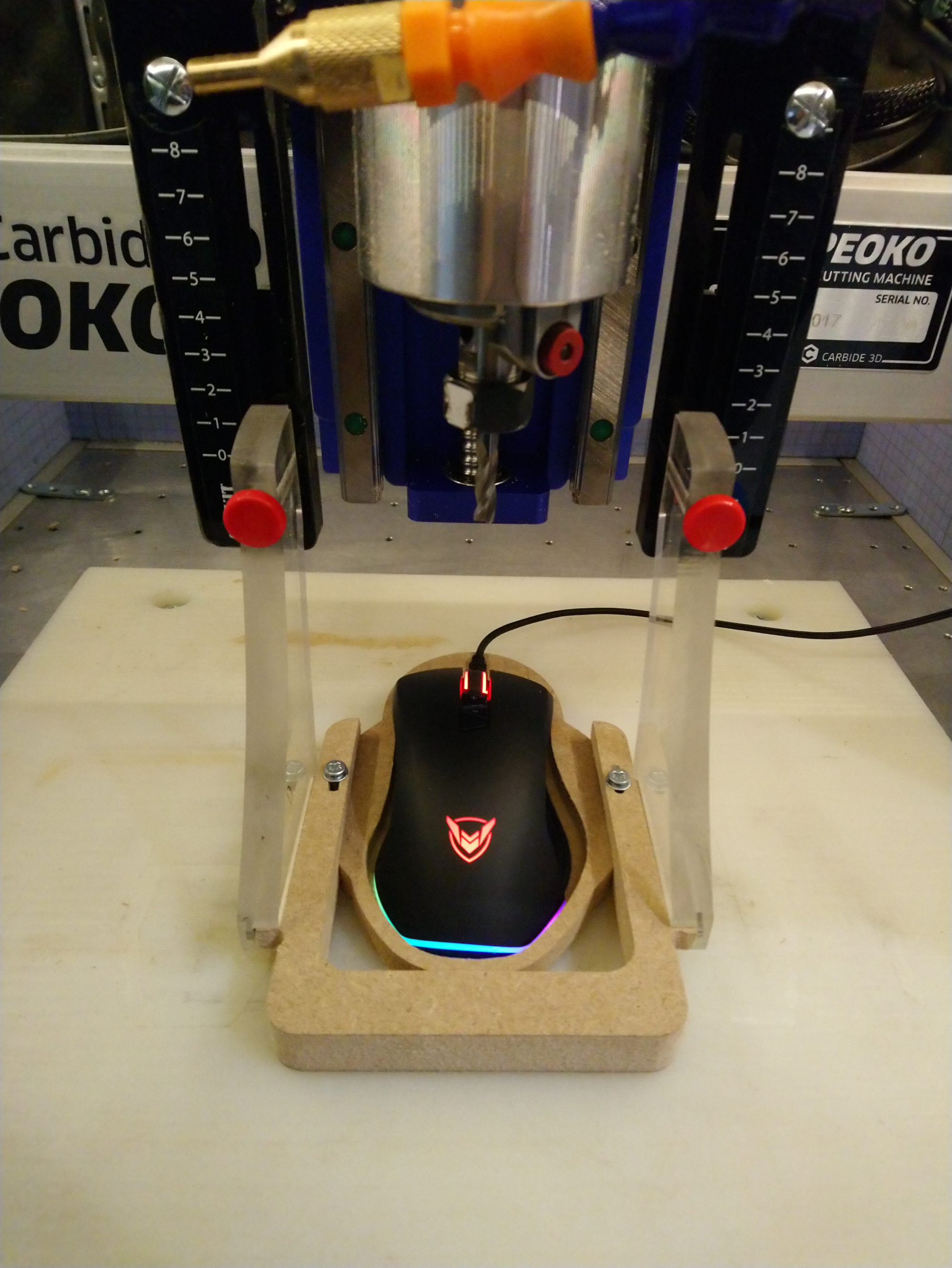
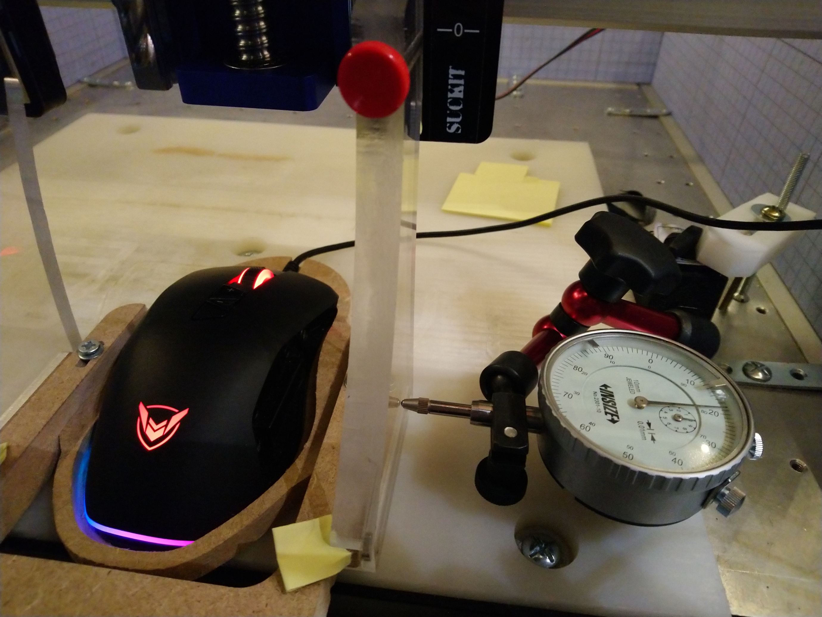
then opened the image in Gimp, traced a vector outline, imported it in VCarve, scaled/tweaked it a bit, and designed a holder that:
fits the arms of my Suckit dust shoe
has the center of the optical sensor at the position where the center of the endmill would be
allows to tweak the rotation angle around this center point, to be able to manually align the X/Y axis of the sensor/mouse to the X/Y axis of the Shapeoko
Now the real fun begins: I already know that the PMW3360 has crazy resolution (24.000 dots per inch), but accuracy and precision on the other end are a total unknown, it may be very bad (which would be undetectable when using the mouse, but would ruin the idea to use it as an X/Y calibration sensor)
I have a python script ready that grabs the mouse coordinates, so I’ll mount a dial indicator, and see what X/Y readings I get from the mouse, and whether or not that is accurate, precise, and linear enough to be useful!
Wow you are really pushing the calibration concept. I think your weak link at this point would be the Suck-It mount that may have too much movement for the level of precision you are trying to get. It may not sit perfectly parallel to the work surface, any slop could end up polluting the results. Just my $0.02
Yeah, quite possibly. I just started testing and the first conclusion is that the sensor must be really close to the surface, which makes sense since it is calibrated to see a mouse pad half a mm away.
I want to hover the mouse over the wasteboard to avoid any mechanical contact, so this tells me I need to have my gantry properly trammed to within half of mm (which it is, so that should still work)
A tiny angulation error of the sensor may or may not be a problem as long as it is constant, since I intend to calibrate the mouse readout against a dial readout anyway.
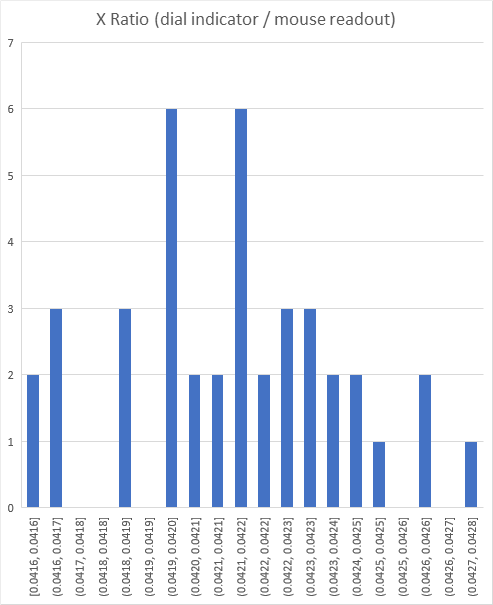
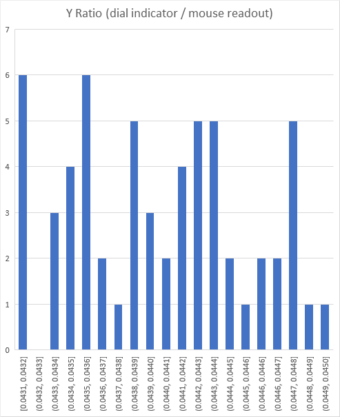
I attached my dial indicator in various places across the work area, and for each position I jogged by 5mm along X (and then Y), back and forth 10 times, and each time captured the dial indicator value and the mouse X/Y value.
Boring numbers and charts aside, this tells me that if I pick a fixed ratio of 0.0421 for X and 0.044 for Y, and recompute values from the dial indicators, I end up getting around 1% max error across the various positions on the work area.
Not super precise, but probably good enough, we’ll see.
Linearity does not seem too bad either :
distance
computed ratio
2.5mm
0.0415
5mm
0.0421
7mm
0.0420
10mm
0.0419
Next: I’ll run my “move somewhere random & grab current position” script and see how the overall work area map looks with this new measurement setup.
Facepalm moment: when you realize you have been capturing data all morning using a borrowed piece of python code to read the mouse under linux, and then you check the code more carefully and see this line:
scaling = 0.046875; #determine the scaling based on trial and calibration
…
I involuntarily characterized the calibration factor…that was in the code, not the mouse. Doh!
I guess I’ll start over, even if this is “just” a linear factor on all values.
Not yet, no. I guess encoders would make sense for real time feedback to the controller, but that would mean changing the electronics completely. And I’m mainly trying to map the very end of the tolerance chain, i.e. the actual position of tip of the endmill, while encoders would “only” help detecting lost steps at stepper level ?
I would think that with an appropriate no-stretch belt (cable), you would actually be able to measure pretty precisely - 2 pulses/degree = 8 edges = .125 degrees/edge. A digital caliper is basically just a linear encoder - convert linear motion to rotary (ie. cable and pulley).
True, but if prototype 1.0 taught me something is that I lack the skills to make something mechanical that is more precise than the shapeoko…
I’ll pursue my optical endeavour and see where to go next