Situation
I’ve got a process for making some 100mm x 100mm x 10mm squares on my shapeoko. However, they need to be sanded after they are made and, since there are a whole lot of them and potentially could be a continuous process, I’m looking at different ways to try to reduce the manual labour of the thing and automate it as much as possible.
Context:
I have an orbital sander setup for doing this manually. I also have a drum sander recently purchased where I’m testing out making a MDF jig with a low-profile clamped setup to safely pass them through with consistent contact start to end
I’ve just asked the forum about a CNC sanding attachment but it seems not to be considered ideal:
Questions:
Anyone here tried making a jig to clamp and run small things through a drum sander before?
What I do for a lot of my parts is to use the drum sander to separate them rather than tabs
Starting with stock thicker than final part, cut the part perimeter to the depth of parts thickness. You can 5hen send the front for final finish, flip over and back sand to separate the parts (and finish sand the parts)
Indeed, I have thought up a concept for a sled. I just wanted to see what other people had to say on the subject before I action on it because of what I perceive to be the risk involved of it kicking them back out 1 by 1 lol. I think I have it covered on that front with the design layout of the sled I’ve got but wanted to field on here for other peoples experiences as I don’t see anything on youtube about sleds for drum sanders, only planars.
I have a very low profile recess and clamping idea which I’m gonna 3D Print and assemble with the help of the CNC drilling the pilot holes for total precision (did this for my surfacing jig I made for them for my CNC)
Well, can you explain your process? How many is “some?”
I design and make things from precut woods that are already rough sanded; usually ¾” thick. I drum sand both sides of the precut wood incrementally until I get it to 0.700” (± small number). When I go to machine the project, both sides are essentially finish sanded. I’ll usually hit the back with a 320 sanding pad and break some edges. A downcut bit takes care of the top-side edges.
I can make like 15 per batch. I should probably clarify a key contraint I have - They are v-carve inlayed, so I can’t sand them before cutting out their 100x100 profiles. Therefore, my process is something along the lines of:
Prepare the end-grain blank
Machine the Male and Female (involves making the inlays but also cutting out the 100 x 100 profiles so can do step-3)
Glue up each in a press stacked on top of eachother
Bandsaw the male excess off
Clean up the glue and flatten both faces of the inlayed 100 x 100 in a surfacing jig on the cnc I’ve made that clamps them in in repeatable positions quickly.
The problem stage - 5b. Step 5 leaves a bunch of step-over ridges on both faces (I do like a 15% stepover). I’ve found anything above 40-60 grit takes forever to sand these ridges out and I want this step to be a quick as possible. I have another jig for clamping them in place for manual random orbit sanding - starting with 40-60grit all the way up to 220.
Problem is, It takes ages but, more critically, also causes the corners of the 100 x 100 square to be worn away faster, leading to my flat surface no longer being flat. This is mainly because of how coarse the grit is to get these marks out. at higher grits, this isn’t as much a concern. I need to get past this first coarse grit stage without screwing the flatness up and then I expect I’m okay sanding manually after that
Step 6 - sanding is what I’m trying to resolve here coz the rest of the steps are as fast as I can possibly make them. The sanding step is now the longest part of the process and not sustainable if I wanna do this, so I’ve invested a bunch to test various approaches.
I have a drum sander which I’m making a jig for which is equipt with 80-grit, but also I have 150 and 220 grit for. This feels like my only option if the CNC sanding attachment ain’t possible
Question - Have you made clamp jigs for passing small stuff through the drum sander before and had success?
What tool are you using to surface the inlay after gluing?
Have you trammed in the machine?
I would first look at reducing the ridges, and getting a better finish from milling. End grain is tricky, but a very sharp high rake cutter should leave these with very little sanding required.
Would a surfacing tool like the McFly work well in this application? It seems like the changeable inserts could be beneficial, though maybe the inserts aren’t as sharp as a more traditional cutter without some modification.
The YouTubers I watch always seem to regrind their inserts razor sharp, trading longevity for results. Is that a skill worth investing in for specific applications like this
I’d be tempted to try the McFly with just the bottom inserts (if I had one).
And I would sharpen the leading edge to razor sharpness.
The vertical inserts have zero rake, 90° leading edge. The bottom inserts look to be about a 45° rake.
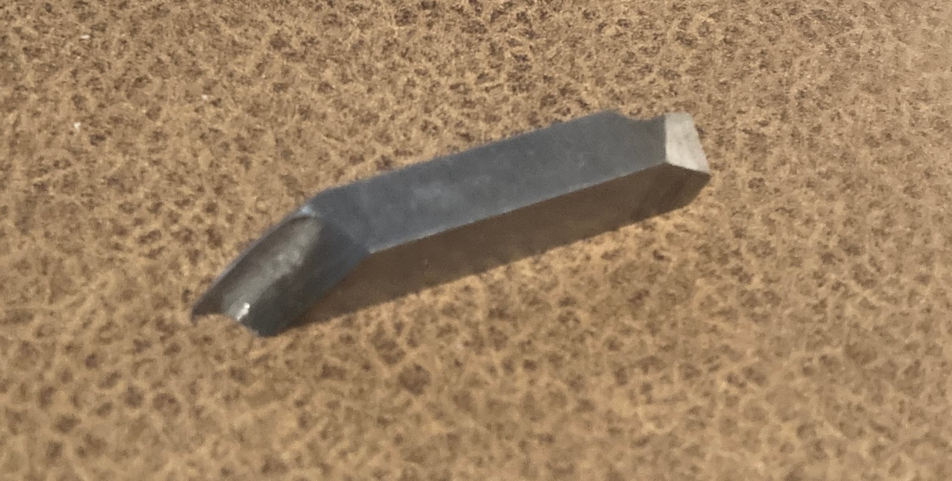
An actual fly cutter with a high rake insert and even a very large radius would be best.
This mounts in a flycutter head at 45° angle. The slightly radiused cutting edge means no sharp corners to leave ridge marks.
An insert facemill with round inserts may also reduce the ridges.
The bunch that I have right now to test my sanding on were done with a 1/4" downcut on the shapeoko pro XXL.
I’ve now sold that and got a shapeoko 5 + 80mm spindle and a tramming tool, so I ought to have a little more success on future surfacing as I will do that with a 1/2" downcut. I have a 1.5" surfacing bit but I suspect it’s more forgiving to me to use the 1/2" for initial surfacing test on this new machine to avoid blowing the items up by accident.
UPDATE (21/Dec/2025):
I have checked the tram of my spindle and it’s within 0.025mm in x and y axis.
My Jig for clamping them in place is clamped to the shapeoko workbed using the t-track down the center using the lowest torque on my dewalt drill of #1 so not to cause any uneven deflection of the 25mm MDF base
I ran for first time on new Shapeoko 5 (as mentioned above) just now @4000 mm/min, 0.25mmDoC and I’m still getting the same issues mentioned.
Question:
Do you think I’m getting these results because I’m using a downcut instead of an upcut when surfacing?
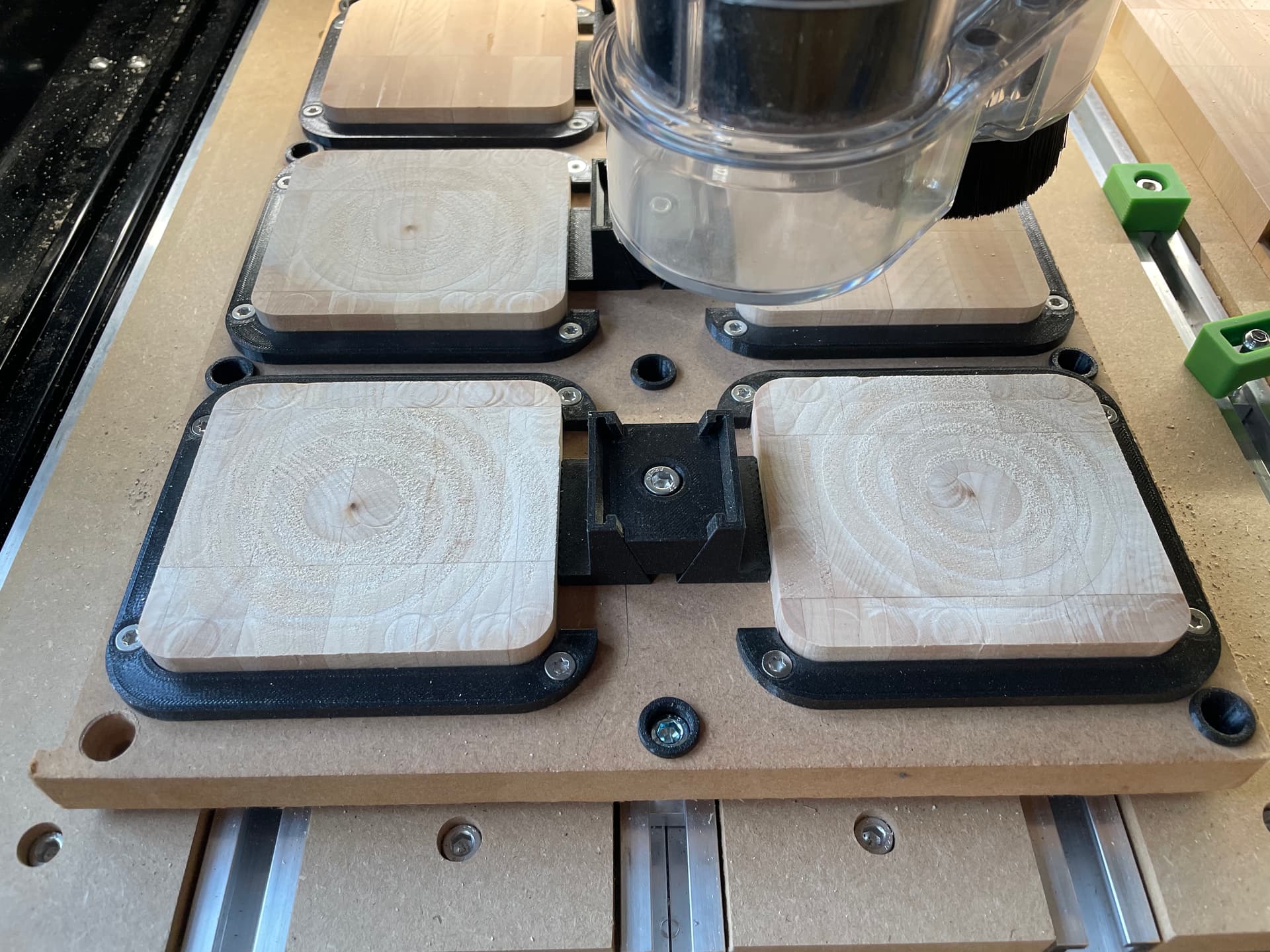
That’s a nice clamp set up but I think that’s part of the problem. The endmill markings on the surface indicate the pieces are moving ever so slightly. The repetitive overlapping swirl marks are indicative of this.
After looking more at the photo, you statement of clamping only down the middle I you can see the outer edges are not flat on your spoil board. This will allow the downcut bit to put pressure downwards while over the outer locations and ”relax” the pressure when the bit returns to the midpoint of the jig fixture where it is torqued in the T track.
I have a couple of recommendations for your clamping setup. The way you printed your wedge and spreader clamps has created the layered steps such that when you are clamping the wedge down the layer lines have to snap past each other. If you zoom in on it it’s like two sets of Lego blocks in a stair step fashion having to slide past each other. I recommend reprinting those wedges and spreader clamps on their side so that the layer lines are going up and down the ramp instead of across the ramp.
Also as @Redlander observed, it does not look like you’re mounting board is flat against your spoil board. I would get something like 1/4" thick aluminum plate and make 4" x 1" plates with a hole in the middle for your screw, and add additional through holes for the other t-tracks and thoroughly clamp your mounting board to your spoil board. You are correct that you don’t want to apply so much force that you warp your mounting board, but the other side of that coin is you need to have it flat and tight up against your spoil board.
Edit: also, PLA and PETG are very slippery Plastics. Even with your clamping they may still be moving due to the vibration and cutting forces. It would be worth you printing one more pair of clamping brackets with your 3D printed bracket slightly larger so that you could glue in a really thin strip of cloth backed sandpaper. Even something as fine as Emery cloth would probably provide enough grip.
I would also like to take this moment to recommend these Thorlabs aluminum clamps. They are the most reasonably priced aluminum clamps I’ve run across. If anyone has found decent clamps for less, I’m definitely interested
The CL2 clamps are the largest ones they sell, at 3" long, and I use them for larger stuff.
The CL3 clamps are the ones that I use the most for medium to smaller size things. They are only 2" long.
Both of those clamps are nice because they have a threaded hole where you can use another screw to adjust the height so that you’re always clamping parallel. And they come in 1/4" and 6 mm flavors for both sides of the pond.
Thanks everyone for all the advice! Cool ideas all around. All of you are correct that the setup is not the most rigid which most certainly is the core of the issue here.
The Latest Result: I want to update on my efforts today - I’ve significantly improved the results in the past hour or 2. Thanks @Tod1d for suggesting I could get better results and to continue to focus on improving the surfacing procedure. This has paid off.
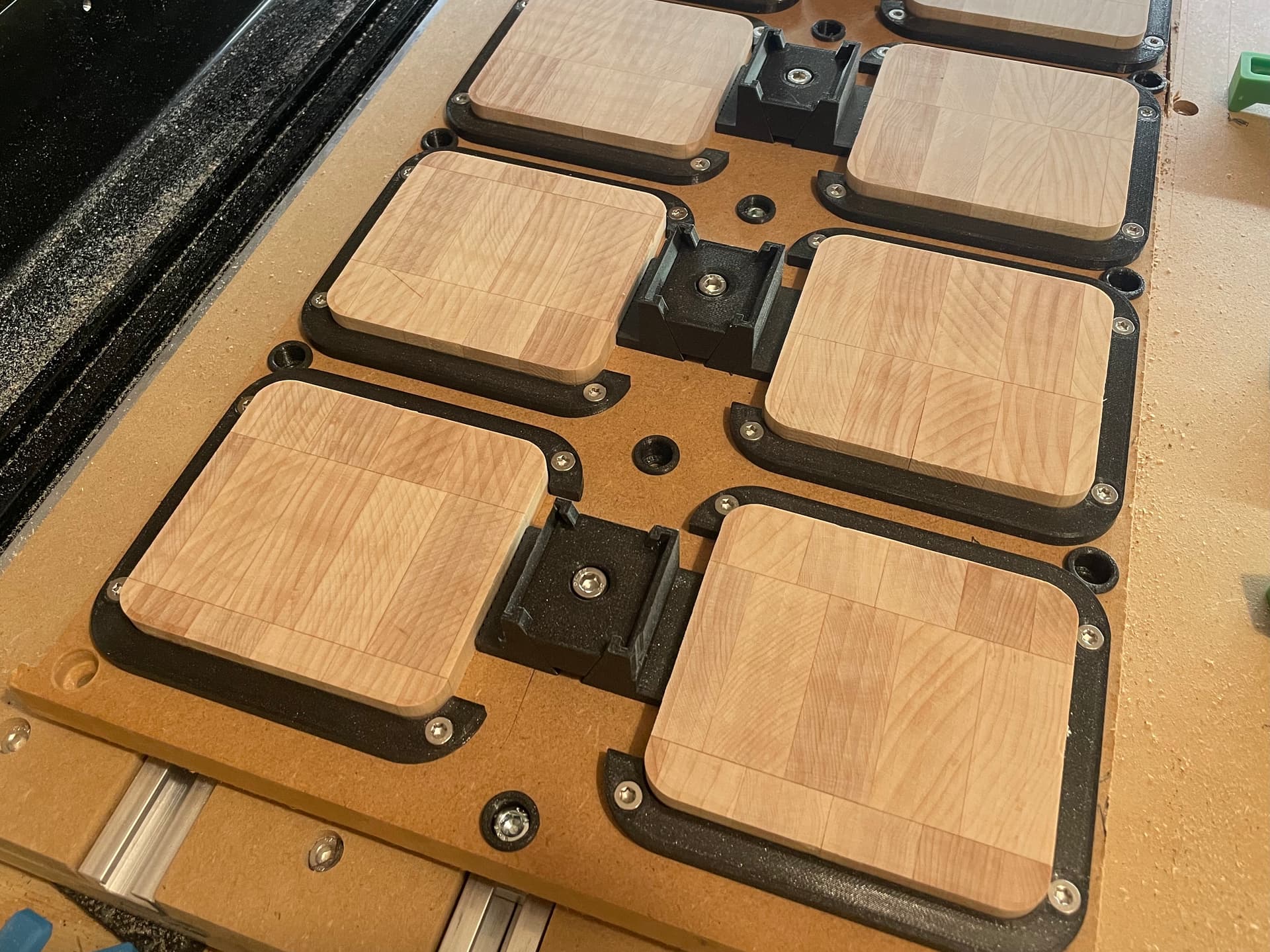
It is now the flattest it’s ever been: no deep ridges or swirls. There’s ridges but they are very, very minor and could easily sand out in a few seconds. I believe I can start with 120/80 grit instead of 40grit, a VERY significant improvement for repeatability and time saved.
I also have noticed for the first time that the upcut leaves a glass-like finish (picture below) compared to downcut (picture in previous message). Downcut was always my go-to to avoid forces pulling the stock out of the clamp or chipping the inlay - I totally had no idea how much it was costing me in terms of surface finish! Thanks @MadHatter@Tod1d for talking about rake angles or I would not have broken out of this silo.
The Rationale behind the improvement:
Thanks to noticing the swirl markings on the surface, pointed out also by @Redlander, it lead me down a road of thought.
The wanna-be pseudo-rigid clamping jig setup is enabling some deflection/movement. I don’t want to remake the jig though so I need to try to reduce deflections/movements
If so, what is the thing that would cause deflection/movement symptom in a not-perfectly-rigid setup that we’re seeing? Answer: Tool Engagement, as the tool acts as a force on the stock in xyz depending on the direction it’s travelling.
I’m seeing deeper cuts in the stock surface in very specific places. What is the common variable relating them? Answer: (a) where the tool plunges the surface and (b) where the tool changes direction while engaged in the material. aka, It’s abruptness.
Therefore, the main enemy of my wanna-be pseudo-rigid clamping jig causing these symptoms was ‘a lack of consistent directional tool force while engaged in the workpiece’, and ‘abrupt engagement into the workpiece’. Therefore, if I follow these rules, I should be able to maximally minimise the issues:
When the tool is engaged with the material, keep the direction of the cut consistently a straight line to keep forces consistent. Do not plunge vertically into the surface.
Therefore, if you disengage the tool from the material, (a) do the moves that change the direction of the cut and (b) avoid plunging vertically opting instead to attack horizontally.
Additionally, outside of this tool marking issue, use an upcut endmill instead of downcut for better finish.
What I Did:
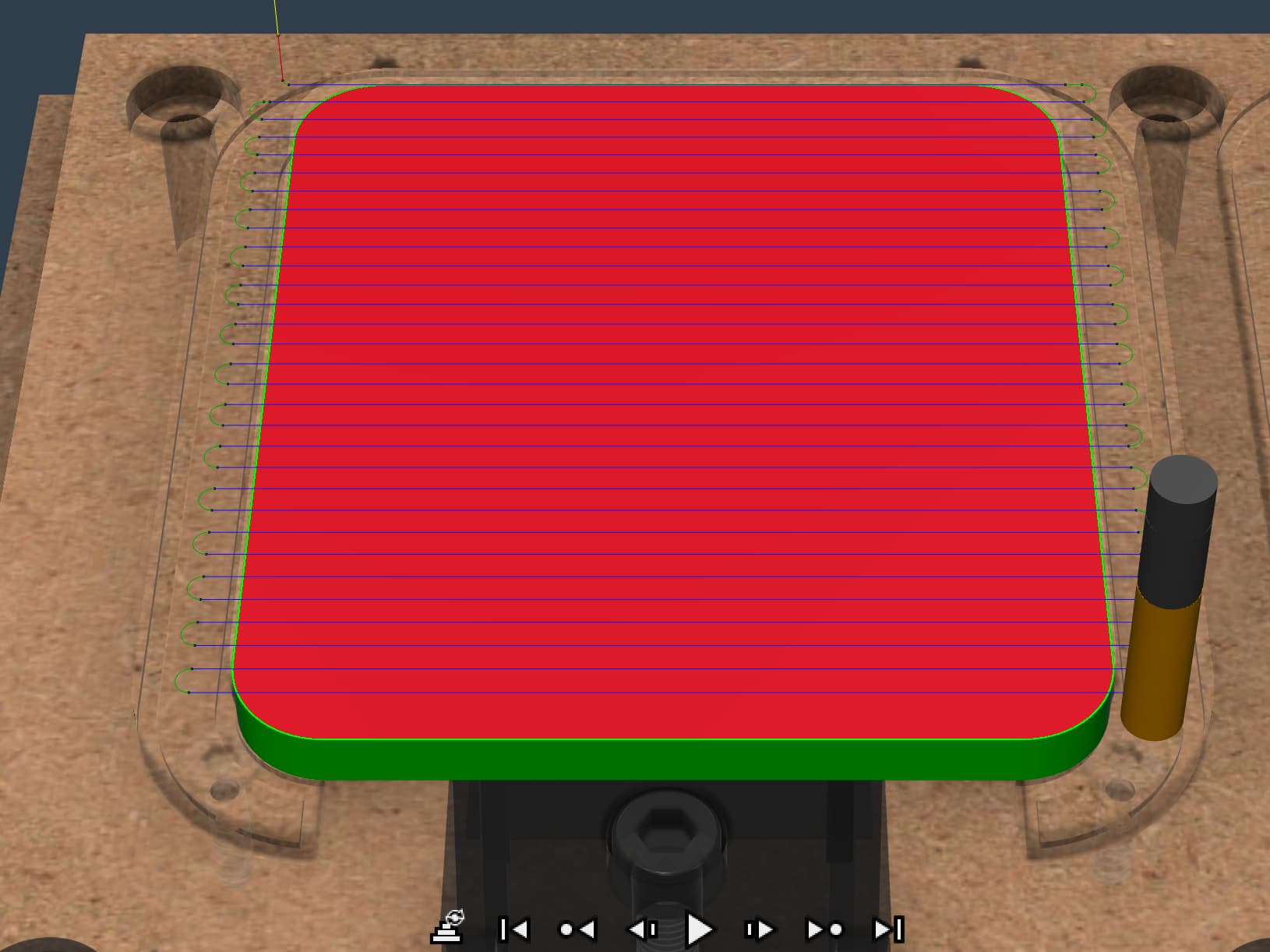
I therefore switched up my 2D adaptive toolpath (which was a directionally inconsistent toolpath of concentric circles) to a simple facing operation (straight lines back and forth engaging laterally from outside the stock boarders) where it does the change in direction off the material. Now, I’m getting a surface which I feel confident could be sanded out fairly quickly with 120grit and above. A massive improvement on my situation before