I recently started a project that requires a fair number of relatively accurate holes in brass and other metals.
The holes are ~2mm in diameter and would ideally be accurate enough for a light press fit.
I tried the naive approach of just pecking with an exact 2mm diameter end mill which (obviously ) resulted in an oversized hole.
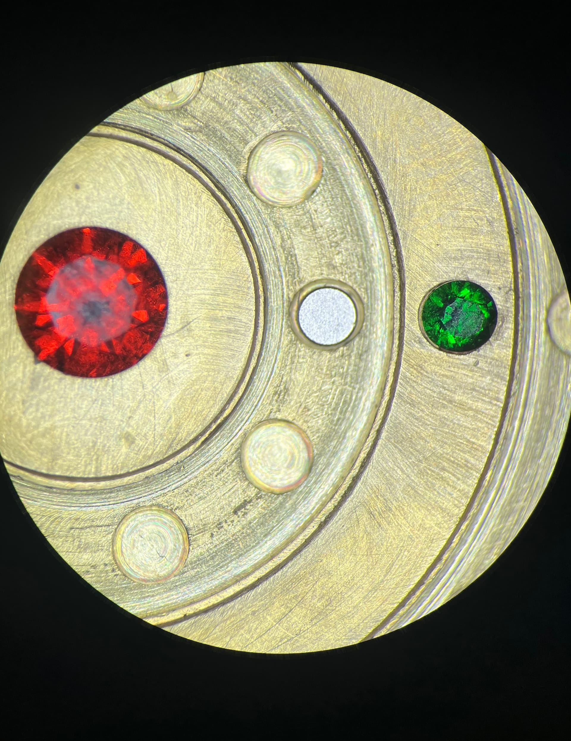
Fortunately, the recent purchase of a stereoscope makes it trivial to share exactly how terrible my holes are! I’m kicking myself for not picking one up sooner given all of the small-ish things I do…Need to get a real adapter for my camera though, only iPhone through the ocular for now but it’ll do.
So what would folks recommend for making accurate holes of this diameter quickly and efficiently?
It’s worth noting, the depth of the hole isn’t terribly important and neither is the bottom feature. It just needs to be deeper than 1mm but less than 2. So a twist drill would work out fine.
The position of the hole is not super critical either. I’d rather risk a tool walking a bit than go through the hassle of a tool change.
Thoughts I’ve had so far:
Plunge with an undersized end mill. I’m not sure how repeatable this would be. I imagine pretty good in the same material but I might have to characterize it for each new material?
Pocket with a smaller, more fragile end mill of say 1.5mm
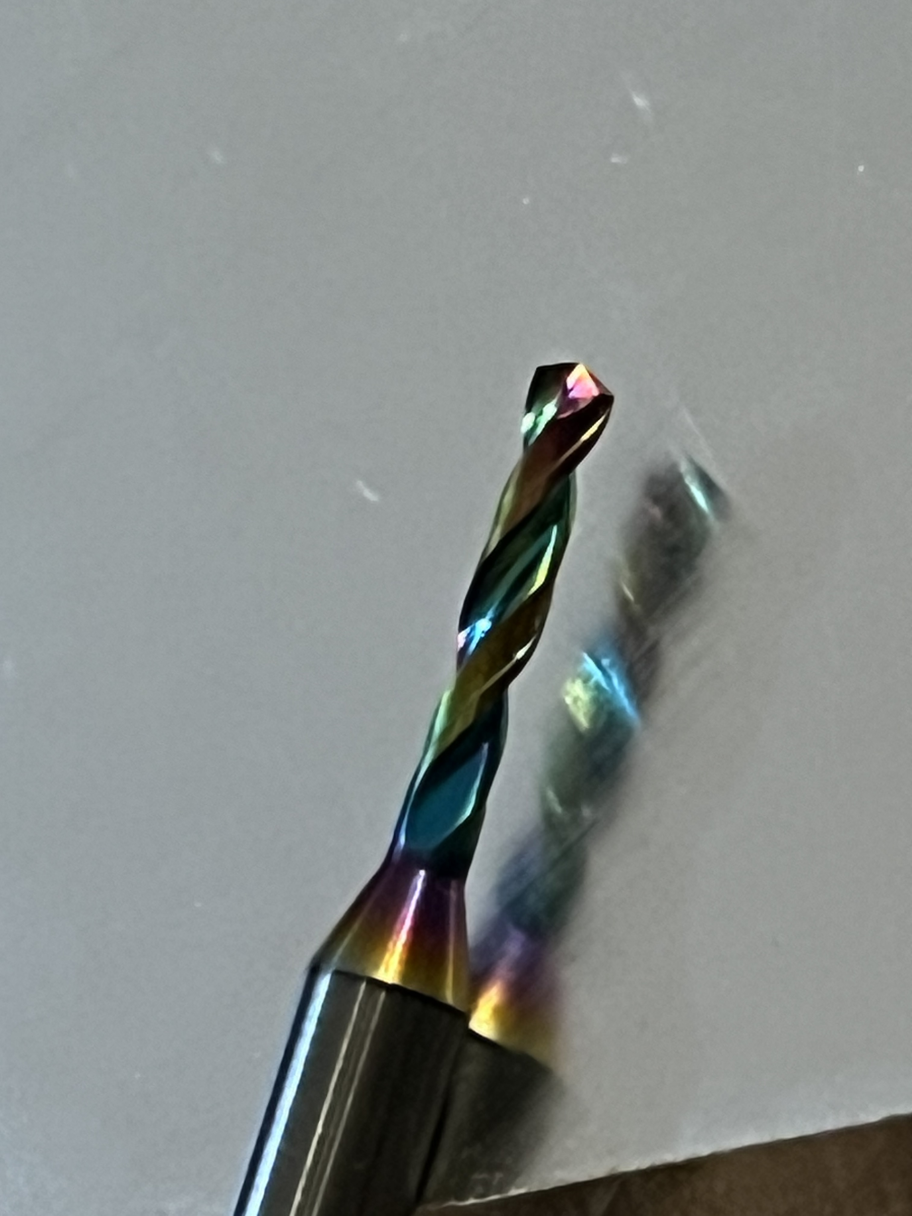
PCB Drill slightly undersized. I’m not sure how the tool would respond if it doesn’t have a spot to start in. I fear walking would cause tool breakage?
Suck it up and properly spot drill and tool change to an appropriate tool
Hope that someone knows of some amazing novel tool/technique that solves all of my problems
Obviously I can create really accurate, clean, round holes with the nomad 3 and other tools at my disposal…I’d just rather not go through 3 tool changes if all I need is “good enough”
Note that any sort of suggestion about this assumes that the machine is mechanically sound — please work with the folks at support to verify that before looking into other aspects.
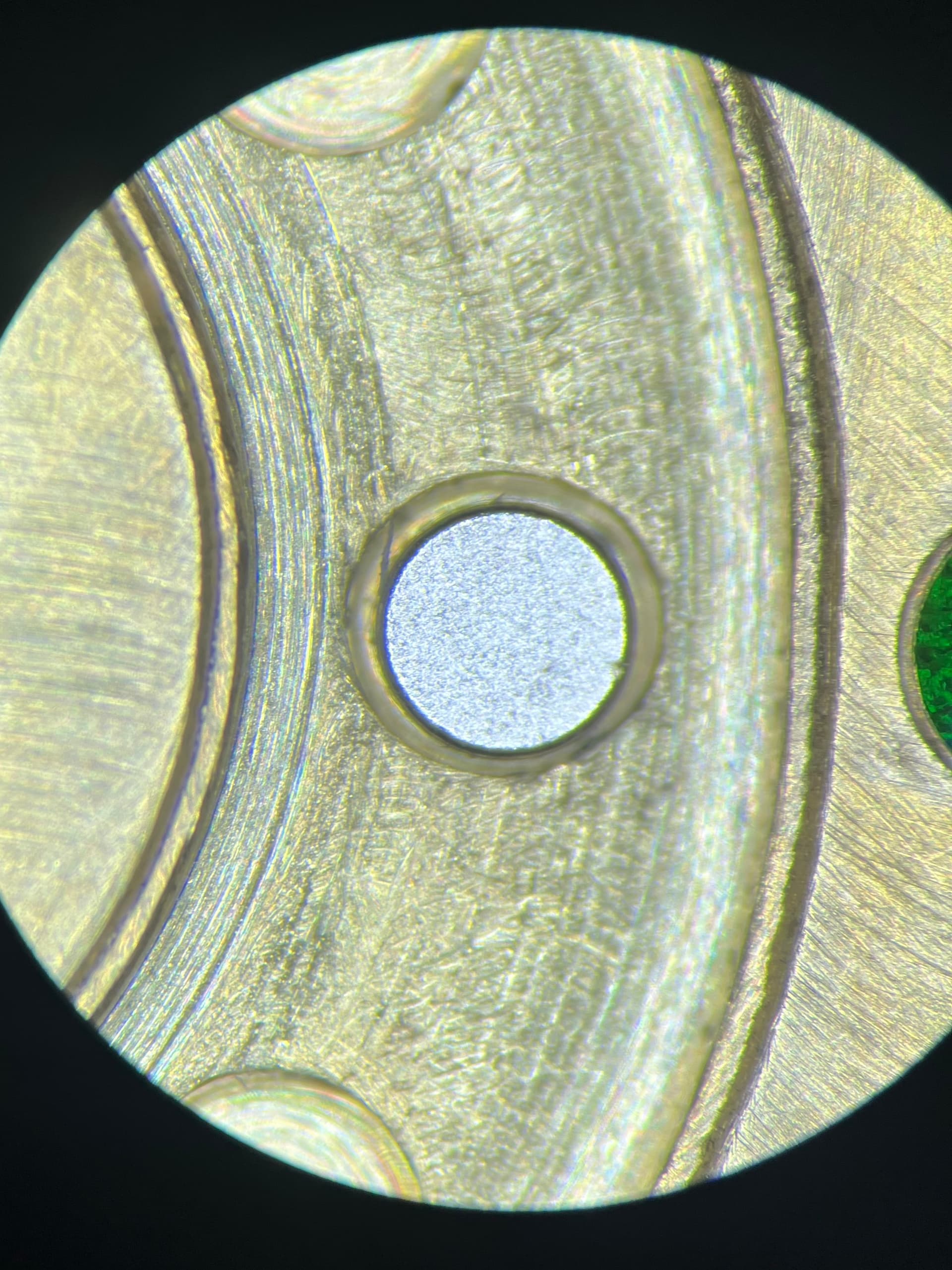
I’ll reach out to them after the holidays just to verify. I expect the machine is doing ok as it’s very consistent in its oversize cut of these 20 blind holes.
The end mill I used for that cut was 2mm with a plunge that was probably too aggressive. The resultant hole was maybe ~2.2mm.
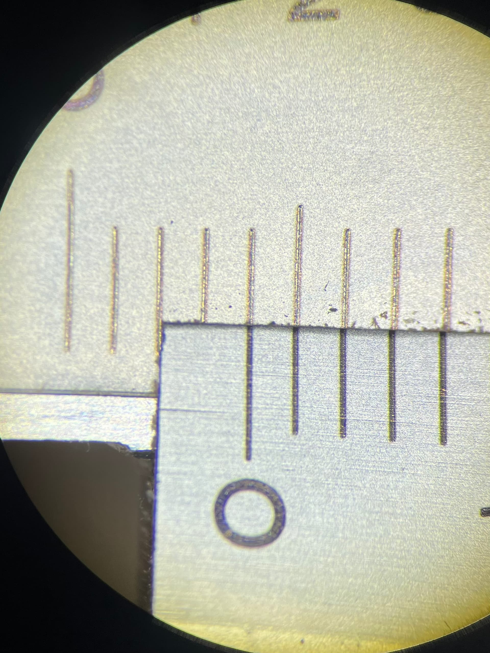
More evidence that the machine is healthy would be the slot cut in the same setup with the same tool before drilling. It was supposed to be 4mm wide and it is near dead nuts 4mm. Maybe 3.98 which makes sense considering I skipped the spring pass.
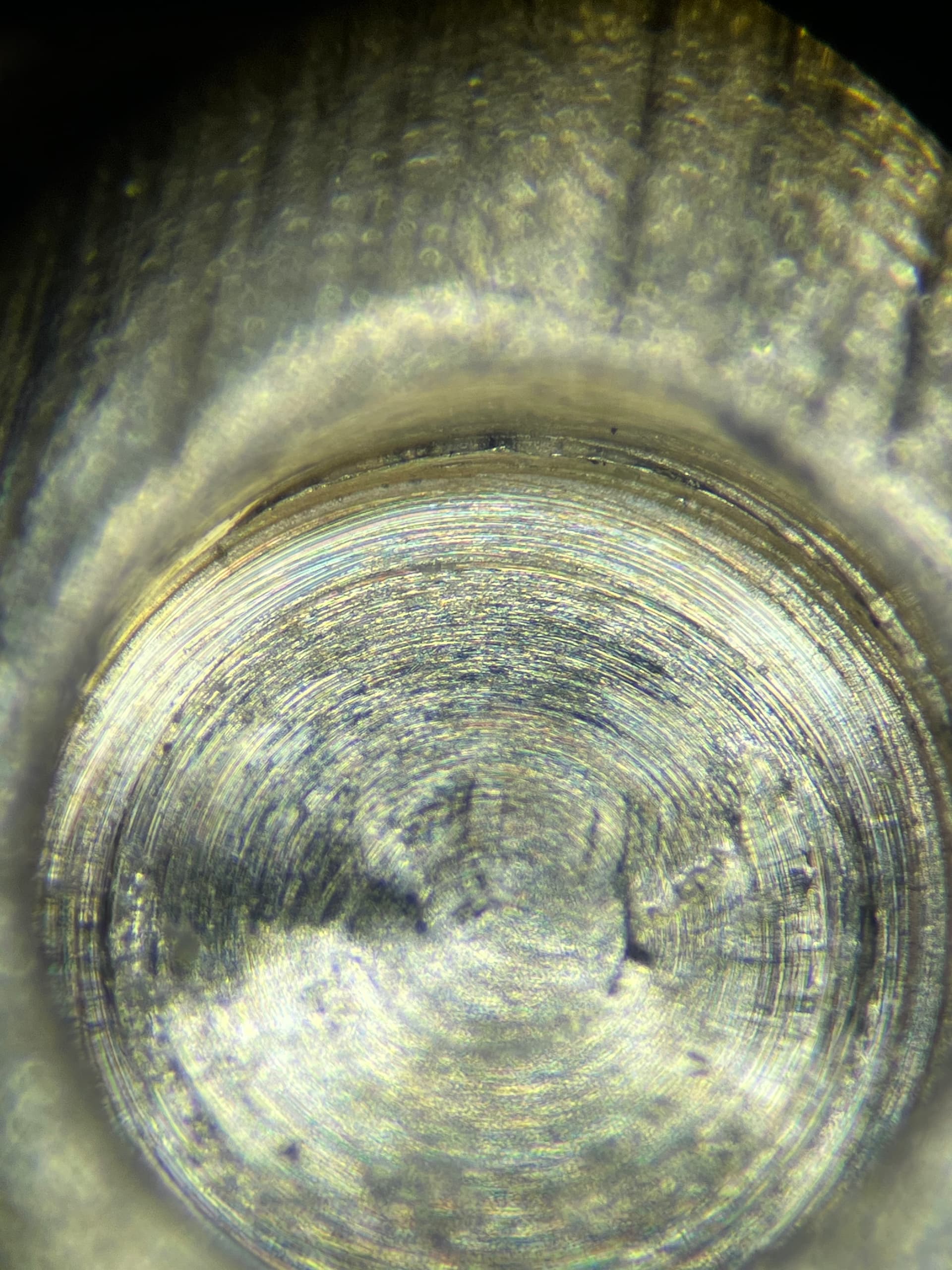
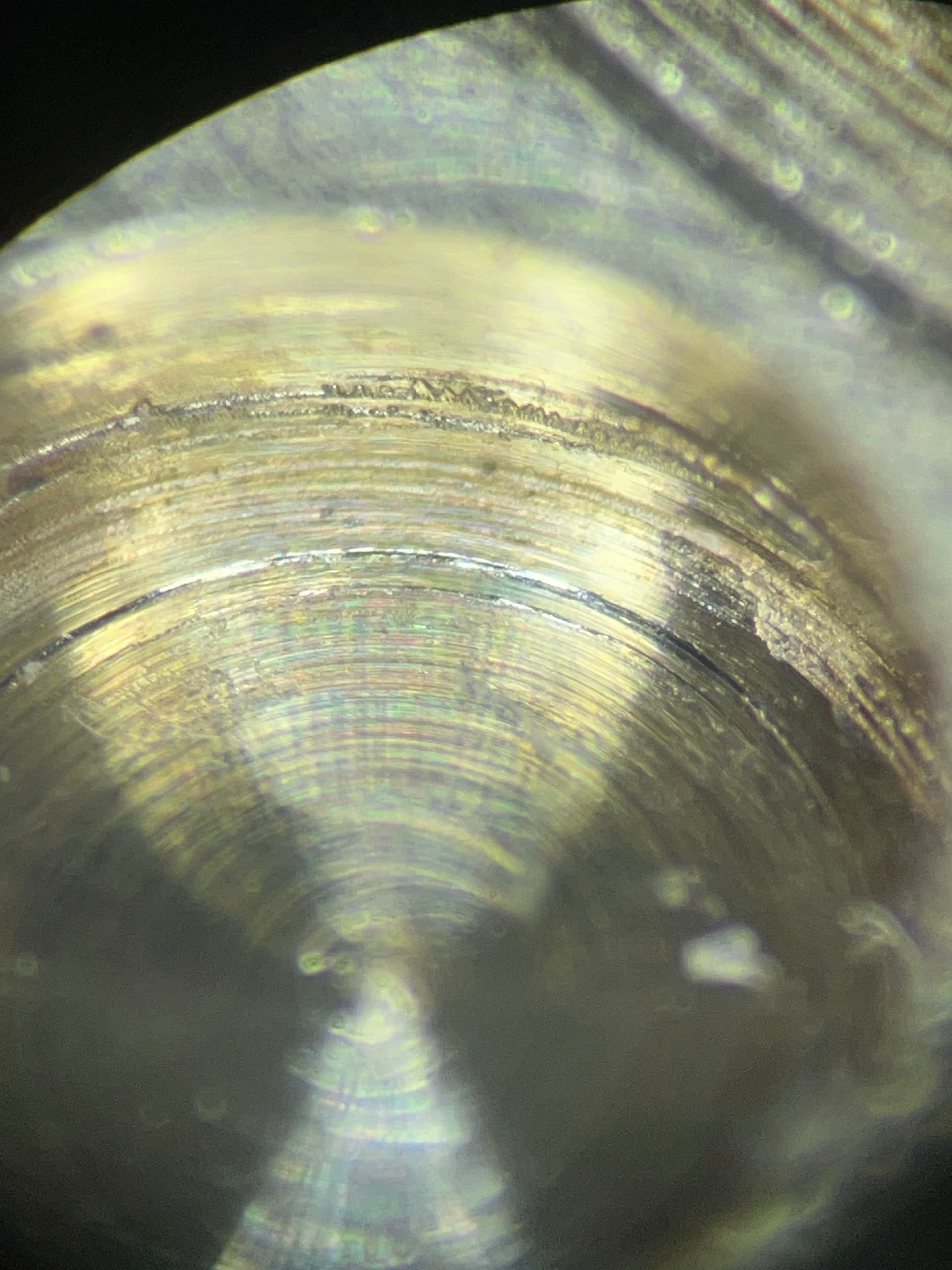
I tried to get a close up of the interior wall of a hole. I don’t know how useful it will be without any depth but we’ll try. It looks to me like the material was poorly sheared or maybe smeared from recutting.
Maybe an overly aggressive cut could “pull” a chip away from the wall instead of cutting it away cleanly?
Or maybe the smeared look could be a result of chip recutting. I was using a 3 flute end mill cutting dry with no assist. I was hoping the small depth would facilitate spitting the chips up and out but maybe that was too optimistic
It’s surpassingly difficult to find good close up comparisons of different cut qualities.
These photos are at a pretty extreme angle to try and get more of the wall in focus. Depth of field at 90x optical zoom is rough.
It also looks like the hole is a bit undercut, like it’s a bit wider at the bottom than the top. Unfortunately I don’t have the means to measure that, so it’s just a gut feeling for now.
I do have a 60 watt MOPA fiber. I’ve done some deep engraving but I’ve not tried to do anything that requires dimensional accuracy. I planned on cutting the gem seats with the fiber since they’re pretty forgiving but I’ll look into cutting these blind holes as well.
My worries about the laser are:
The time required to remove this much material compared to the mill
How many coins I could do in one setup without skewing the holes at the extremes of the work envelope. Marking the numbers is shallow so the skew isn’t as relevant, if it means I can’t mark as many coins in one setup it’s probably not worth doing. We’ll see though.
I’ll go ahead and do a side by side by side by side…by side comparison on the same piece and report back
1.5mm square two flute pocketing to 2mm, 1.8mm square two flute end mill straight plunge, 1.8mm PCB drill, 60w fiber relatively straight on, and finally the 60w at the edge of the work envelope.
Should be a fun to compare cut quality and time required to complete each. I’ll also outline if it would require additional setup or if it works with the current strategy.
I guess the difference here is that I’ve never had to try to optimise a process. I have used the Nomad to cut seatings for bezels in silver that is undulating after being reticulated. I have found fibre will give much finer detail (tight corners) in 3d reliefs than the nomad more quickly as the size of the bit needed for detail prevents removing material with speed. Both tools need a flat surface, but the laser is more forgiving. Work holding for the laser is less demanding.
Why not drill with a drill rather than an end mill? They are, after all, designed to do exactly what I think you want. The tip of a machinist’s center drill may well go deep enough for you without the wandering and breakage of a skinny regular drill bit.
And I’ve got a real center drill around here that I’ll add as well. I thought about this before and felt like it was a bit abusive using them as a regular drill but…carbide is carbide. Let’s try it out
Fair points.
I knew about the speeds issue, the pcb mills are rated for significant higher speeds and the dlc drill is rated for 24000 as well. So we’re safe on those fronts.
I hadn’t considered the tool geometry. Which is just silly now that I think about it, didn’t even cross my mind
Yeah, I see that as a fallback plan if none of the other tool-changeless approaches are acceptable.
Though it seems the majority of approaches will require at least one tool change anyway. That battle may be lost before it begins.
Still, it’s good experience (the discussion alone has taught me a few words. “Drill mill” writing that one down) and worth the effort in the off chance something sneaks a win
Why not using a 1/16 inch spiral cut router bit, not a drill bit, and have it cut a pocket? Use low feed rate (500mm/mon) and rather high (would think 18.000-20.000) rpm.
I do not have any experience with CNC of metal, but little with hand work with metal I did, and 2it wood I would use the abovementioned settings for a precise cut.
I’ll throw some tap magic in the mix, though unless it knocks this outta the park it probably isn’t worth the additional cleanup. I’d rather do another tool change and cut dry than have to clean each part when I otherwise would not have to. Certainly a good enough idea to be part of the shootout though, so thanks
Regarding the low rpms, I don’t think I can get away with that on the nomad 3. I think the minimum spindle speed is ~9000rpm. My experience tells me the smaller tools really want to go as fast as the can. Pretty sure PCB drills run at 25k at the lowest and can get into ludicrous speeds like 100K+. The sound that makes has to be wild.
Usual preface, I’m with PreciseBits so while I try to only post general information take everything I say with the understanding that I have a bias.
Didn’t see this until now as we were off for the holiday.
You should be fine drilling at the available speeds at this size in brass. SFM in brass even for HSS is around 150-300 SFM. Carbide ones are pretty much all over 300 SFM, sometimes greatly. 300 SFM on a 2mm is ~14,500 RPM. The type of tip and rest of the geometry will determine how much.
In fairness to the other posts, usually PCB drills are listed for speed in FR4. While the drill is fine running at those speeds it probably won’t match the material well.
DLC coatings can help but are relatively heat sensitive and depend on the percent of sp3. There are a lot of them that are only marginally functional. No idea on that one.
The thing is, with either this or using an end-mill as a drill you HAVE to feed it fast enough. If you don’t, even ignoring grinding the swarf in the hole, you’re generating a lot of heat, have possible melting, are getting a built up edge, etc. Probably going to need around 0.001" (0.025mm) chipload. That’s around a 29 IPM (737mm/m) plunge for a 2 flute.
More in general to doing this without a tool change.
You could find the right size drill. If you're feeding fast enough they should stay pretty true to size. However, you need to compensate for spindle and collet runout in addition to rigidity (tool and machine). One other thing that might be useful if you could find them in the right size would be "medical drills". They were used for making holes in medical needles and the like and are MUCH stiffer. I'm not sure I've ever seen one that large though.
If using an end-mill I would do a ramp/helical bore. That will let you control the size somewhat. However, to also control the chipload you need a decently smaller tool to keep from having to adjust for chip thinning and you will be limited in feed due to acceleration. So if trying this with an end-mill you are probably better off using low RPM to stay in the range of the functional feed at small segment lengths. Otherwise you fall into the same issues as cutting/drilling too slow
Hope that’s useful or you already found a solution. Let me know if there’s something I can help with.
Look up “Stereo Microscope” and you’ll find what I’m referring to. It’s generally a going to get you some reasonable zoom, say an upper bounds of ~90X optical magnification. I usually use it around 20X.
The “Stereo” part is important because it gives you depth perception even at magnification. This is great when you’re physically interacting with the item under zoom, as opposed to just taking a photo. For this reason, these stereo scopes are often used in electronics and gem work/stone setting. Knowing where you are in space with your soldering iron is mighty beneficial.
I ended up with an amscope something or other. They’re not cheap but man was mine worth it for me