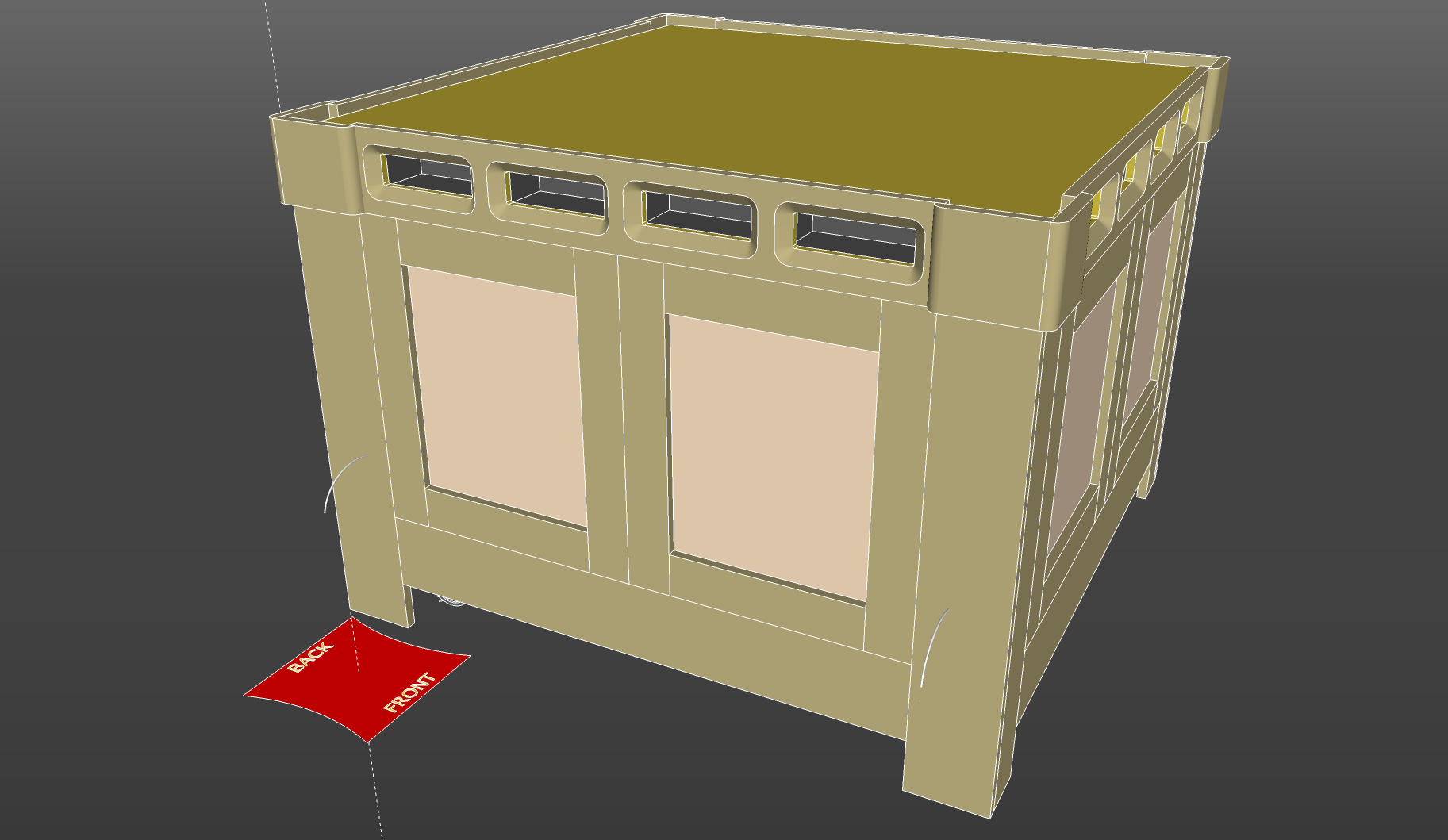
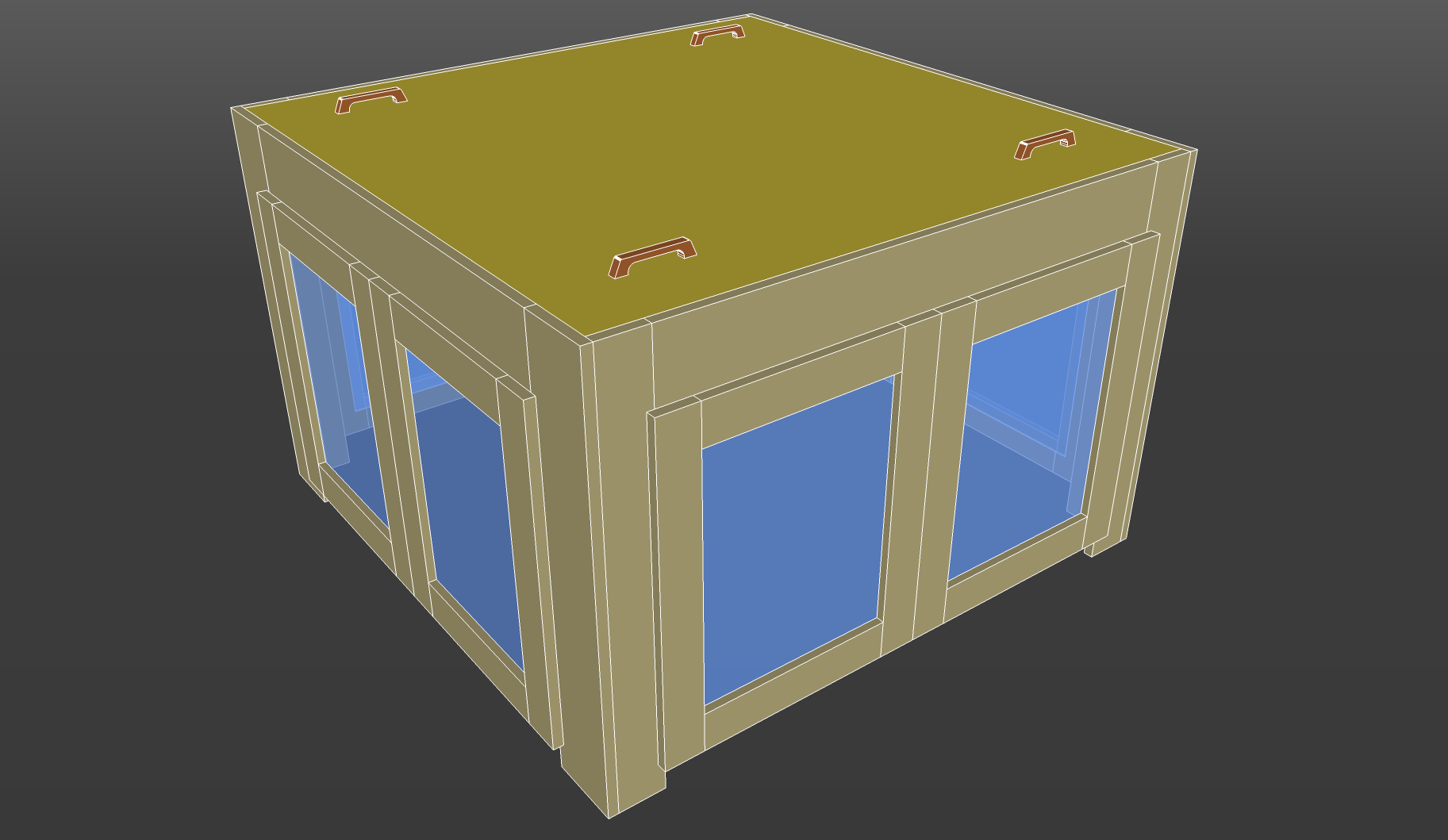
My inspiration here is from @JFischer911, and I have borrowed some basic parts from his enclosure. However, I have adjusted part sizes so the parts can be made from basic dimensional lumber and sheets of MDF.
My design creates a two-part enclosure for two reasons: 1) I need a base for my new router and 2) I need a way to keep the dust out of my shop. The first part will get me started, and the second part can be made as I have time.
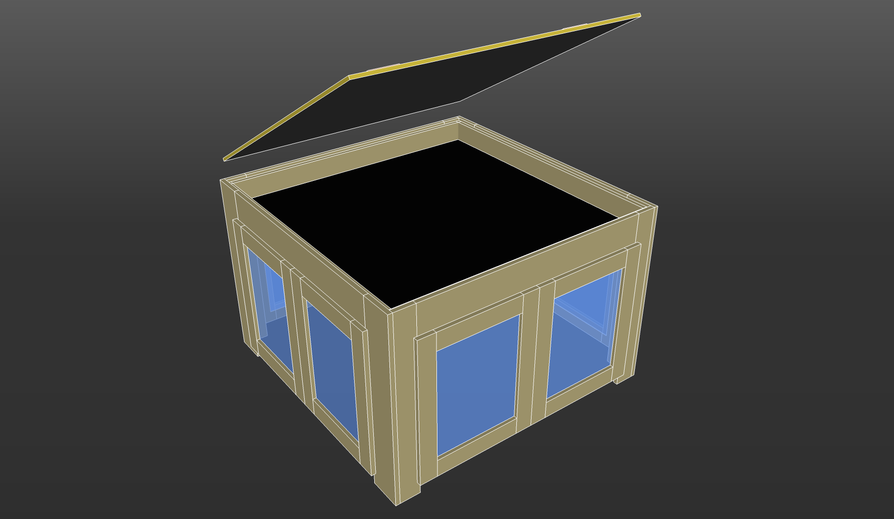
The images I’ve included are stylized, but I am working on dimensional drawings so that I can build this for myself. I’m thinking I’ll make those drawings available.
@JFischer911 got me going with what is called a “torsion box” for the base of the router. Then I just started using 1x4 and 1x6 lumber to build up the sections.
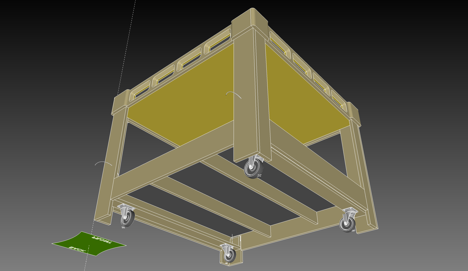
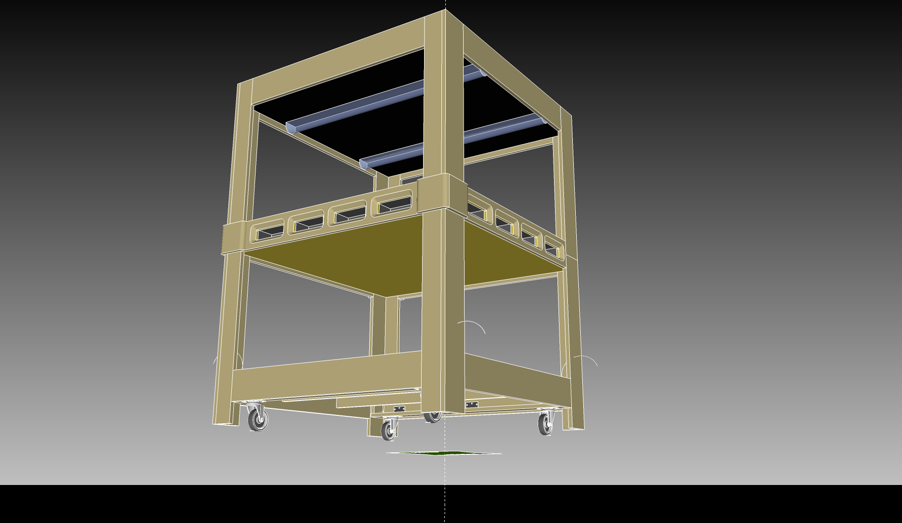
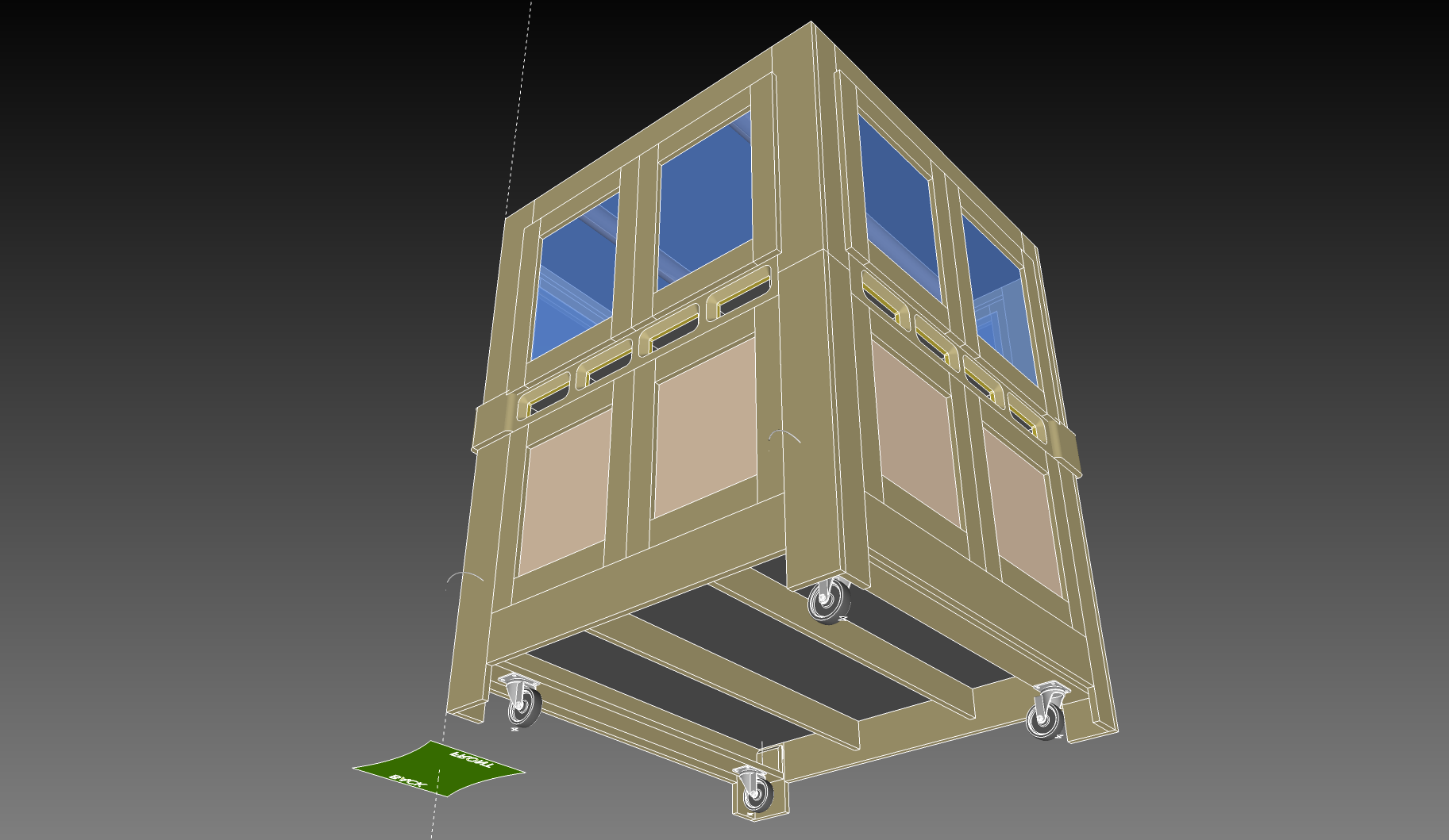
The enclosure/table doesn’t rest on the casters, it rests on the corner feet. In the interest of simplicity, I haven’t provided a leveling mechanism. (Simple shims will certainly be enough in my new workshop, but there’s plenty of room for improvement.)
The mechanism around the casters simply provides a way for moving the enclosure/table around. Visit this New Yankee Workshop Episode 1407 summary to see where this comes from. The caster system “falls” into place when the enclosure is lifted on each side. Most of the time, it is tilted up out of the way.
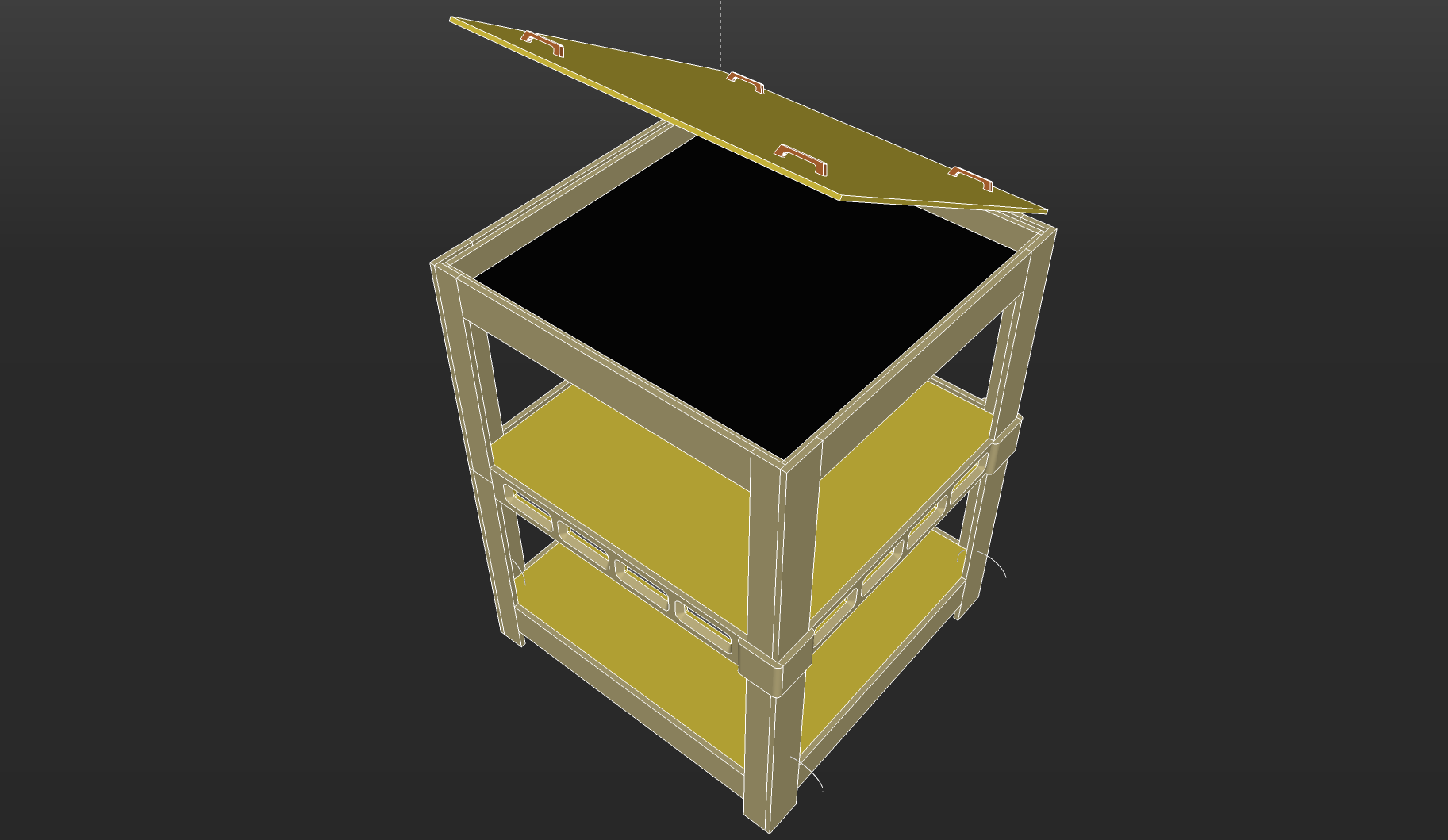
Another, sort of hidden, feature is the area at the top of the enclosure.
I’ve included a space where my super LED lights can be mounted, and the wiring can be done in this enclosed area. The panel here is perforated hardboard so there are plenty of holes for bolts and wires. The top MDF panel is easily removed for access.
Also, I intend to experiment a bit with adding vacuum hoses to this area. My original intent was to draw “floating” dust up into the box to keep the enclosure free of small particles (perhaps a bit optimistic. Perhaps some of the perforations would have to be closed to get the proper draw.)
Then I got to thinking about making a small diameter vacuum hose “loop” in one accessible front corner for the hand-held vacuum detail hose. Placing the hose back up into a magnet-aided holder provides some vacuum for that boxed in area, too.
I would consider either adding an overlap along the top cover edge (maybe with hinges), or modifying the top cover to overlap the top edge of the sides. My concern would be that it might easily fall down onto the Shapeoko when trying to open or close as you added that you might want dust collection, which makes the cover awkward (already because of its size and relative height from the floor. let alone the the hose and stuff), and that would probably need to be disconnected prior to removing the top cover? There are some quick-disconnects available to make this less of an issue. Then would you hang this top cover on the side of the CNC enclosure or just lean it against it on the floor? Otherwise, it looks interesting.
Of course your thoughts are significant to me, but I have not really thought through all the possibilities. (It was really easy to push that top open in Sketchup!
I have even considered pulling that lid up to the ceiling about a foot so the area could be worked in or vacuumed out of leftover dust.
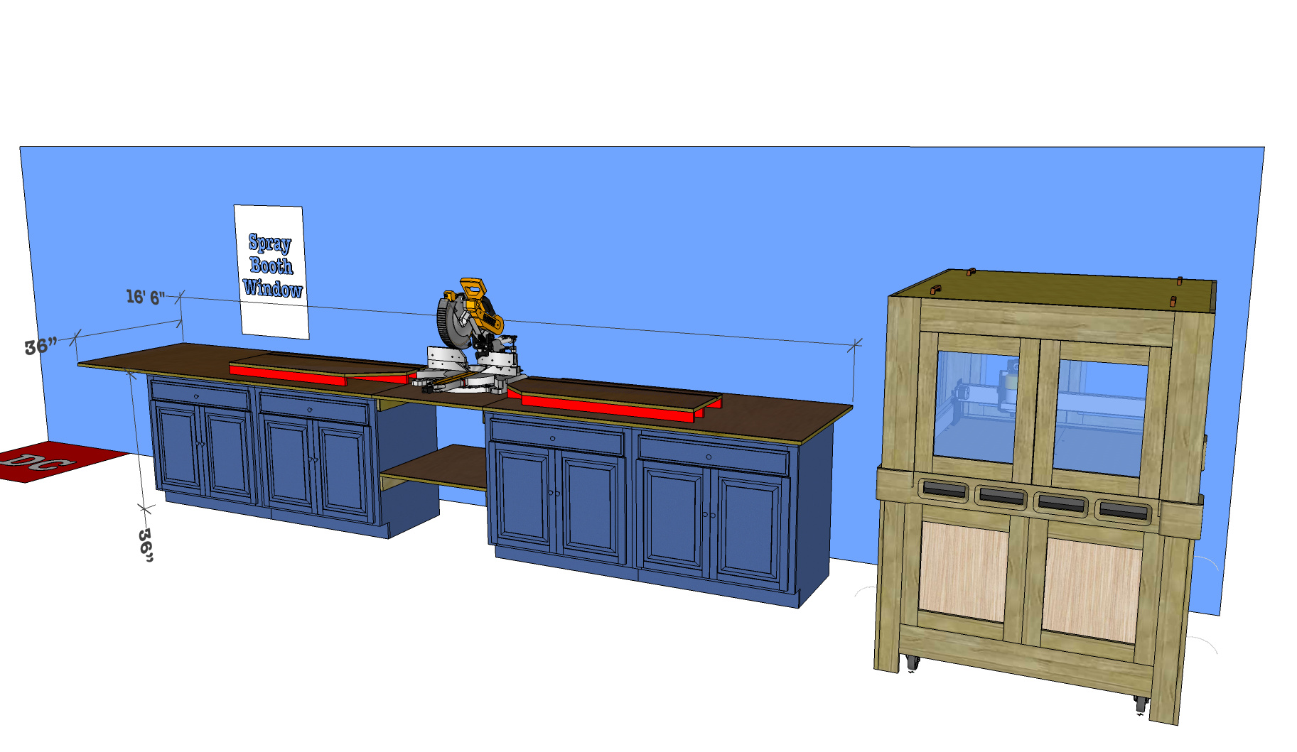
Here is what I’m currently working on while the rainy season is keeping me from continuing with the construction phase of my new shop.
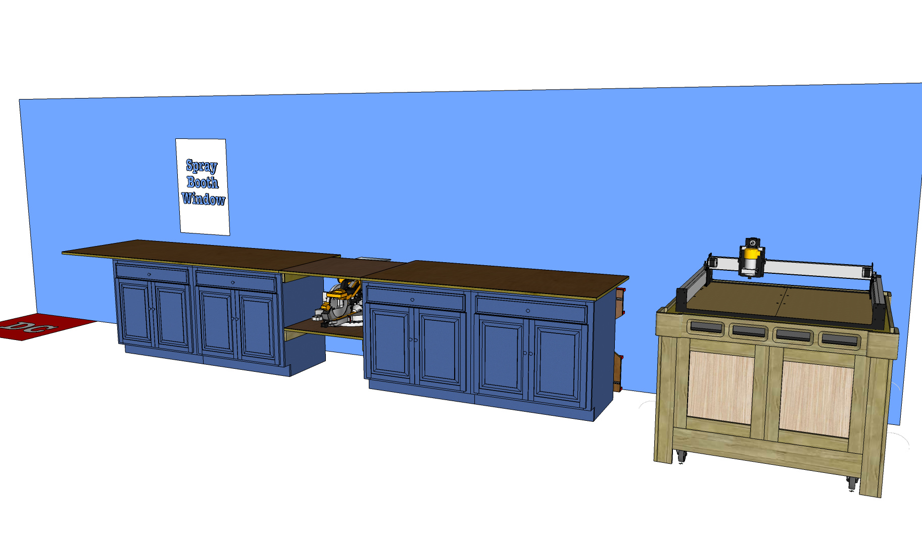
The base and enclosure for the Shapeoko will fit into a corner area while my miter saw table will fit along the north wall. I have about 30 feet of wall space to work with. I’m thinking on making the left side overhang into a down-draft sanding area since my spray booth suction will be on that wall over it. (That’s why I haven’t finished supporting that overhang.)
The miter station design allows me to use standard base cabinets and a way to convert that table top into a work and assembly table.
The DC in the left corner is positioned well for that north wall, but may create a challenge to get suction to the center of the workshop for my table saw. Won’t be too difficult; perhaps a suspended duct.
Anyway, suggestions and thoughts are always welcome!
Yep, I put that window there for just such a purpose. I’m tired of my benches and tools looking like a damn speckled rainbow!
The workflow is a little off, but I’ll get used to it. I’ll have french-cleat walls for hanging stuff. The cabinets have flat shelf/drawers for tools and equipment.
Regarding the adjustable casters mentioned above, I took a slightly different approach.
My XL cart, currently under construction, is about 53 wide by 34 deep. It’s a stout 3/4" plywood box with a 3" thick top of laminated MDF. No torsion box. I did try 4 standard 3" casters from HD and discovered just how out of level our tract house garage floor is. The cart’s primary location is the only spare space in my shop, up against a wall, under a window. Rolling the cart anywhere else resulted in one wheel or the other lifting off the ground, which would no doubt lead to some sort of wracking or instability.
After toying with the idea of a 3-wheeled cart, I expanded on this with a design I first noticed while delivering appliances in my college days. Some washing machines used a pivoting beam across the rear of the unit, with the rear feet at the ends of a beam which pivoted at the rear center of the unit. The effect was a unit that automatically compensated for unlevel floors. The pivot point acts like a phantom “3rd wheel”.
So I built one. A 42" laminated plywood beam, pivoting on a piece of 1 1/2" galvanized pipe. Single castering wheels at each end proved a bit unstable as the castering action placed them off center, so I switched to a small metal plate at each end, mounting two smaller casters set as far apart as possible. Now I realize this doesn’t assure the cart top will remain bubble-level, but I figure the main concern is a top that wracks, twisting the spoil board. As long as the top and spoil board remain in the same plane we should be OK.
And it works. I can run any wheel up on a 1" thick wood chunk and the cart won’t wobble. Now as built, it was possible to force either end down at a funny angle with enough weight, so I added a rude damping system to the tops of the ends of the beam, by gluing on a small pyramid of foam made from a cut-up HF floor mat. They barely touch the underside of the cart, compressing increasingly as the beam moves. This greatly stabilized the cart but doesn’t detract from it’s ability to remain flat-footed on the wavy floor. With two locking casters in front, it seems like it should work just fine. I say “Should”, because I haven’t remounted the XL and cut anything yet. At the rate this cart is evolving, . . . and then there’s the enclosure to finalize . . . . Someday soon. Maybe.
I lived in a “garage apartment” in my college days; literally a “garage”. In the back yard of the owner, and he still parked his car in the bay next to our bedroom! He threw a wall and a floor together to make that apartment, so I know what a wavy floor is like.
The design that I presented doesn’t include the casters to level it. Once the enclosure is positioned, the casters are lifted out of the way, and the unit sits on its legs. I’ll most likely have shims to adjust level where the legs meet the floor, but I could add leveling adjusters.


 Perhaps some of the perforations would have to be closed to get the proper draw.)
 !!!
!!!