3/4" is a lot for this size in metal. But probably isn’t the whole issue. That size tooling in metal I try to keep no more than 0.400". Difference in rigidity between 0.75" and 0.40" is ~3.83lb to deflect 0.001" (0.025mm) vs 6.52lb for the same 0.001" (0.025mm). Only way that would effect it that much though is if you were cutting a LOT more than the 0.0014" large chip chipload.
Masking tape and CA is good at these forces as long as it’s not gel CA.
Any weird noises? Did it sound fairly smooth or was it constantly up and down in feed?
I’ve never had that happen as long as it’s completely set. Probably depends on if there’s any additives too. At least in theory it shouldn’t do anything to fully catalyzed CA.
Might also be an issue if the tape is absorbing the water.
Great little tidbits of wisdom here, that lubricant/tape interaction is getting filled away for sure.
I’d like to think that reading it here would be enough to never cause the issue myself, but I’ll be happy to just remember this post after I launch a small piece of shrapnel at Mach 3
@Ed.E I did consider that being the problem for a moment, but I have had no issues with the part moving when going slower and thus more IPA being applied to the part. As such I doubt that is the issue. Among other things I am making sure to adjust the IPA so just enough is being put down to evaporate but not soak the part. Also the features are radially distorted around the part. I do not think the tape loosening would cause that.
@TDA no weird noises. CA glue is the thin watery kind and had cured for 5 minutes before I started the cut. I will see if I can reduce the stick out. I have had issues with the S5 Pro and Carbide Router not being able to go to Z = 0 with smaller endmills in the past. Though my fixture is higher up so that probably wont be an issue here.
I did the math and I think I figured out the bigger issue.
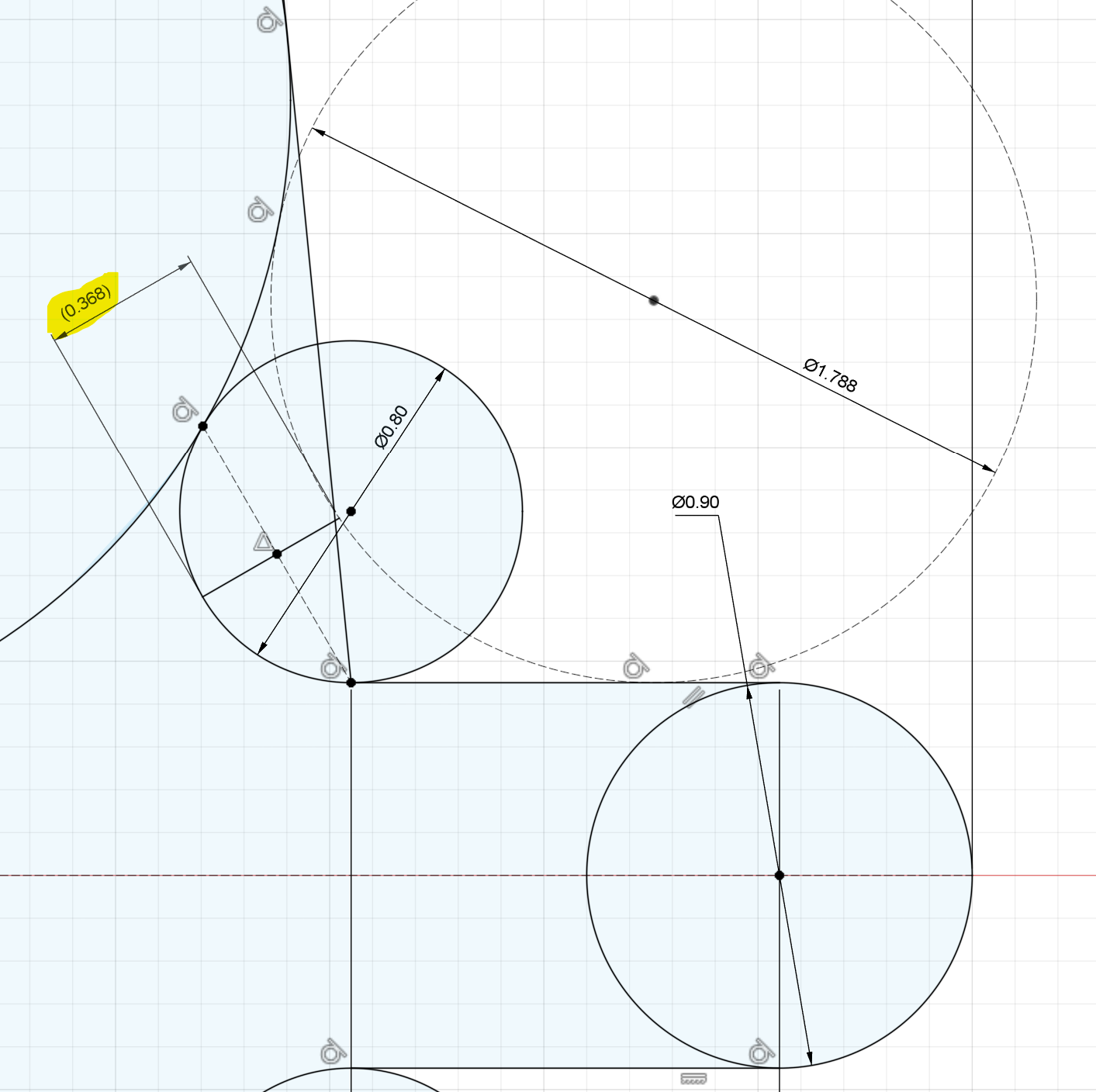
The previous toolpath is a 1/16th endmill doing a contour pass with 0.1mm stock to leave. The inside corner radius of those teeth is 0.8mm. Assuming I understand how Fusion is calculating STL in this instance the 1/16th endmill is being effectively treated as a 1.788mm ( (1/16 * 25.4) + 0.2) endmill. That means that there is around 0.368mm of material still in the corner for the 1/32nd endmill to chew through.
I am trying to figure out a good set of toolpaths to deal with that.
I am usually .2mm off when doing holes in carbon fiber when using 1.5mm or 2mm bits. It’s a combination of tool deflection along with the conventional cutting forces. The tricky part is to retain tolerances on outer cuts like that. I usually just add a tool offset of .1mm for whatever bit I am using to account for the inaccuracy (1.4mm or 1.9mm). If you go this route, your overall diameter of the gear will shrink but your cogs will be closer to actual dimensions. So you may need to make a separate toolpath to do the cogs with the offset tool and another for cutting the gear out at the end with the actual tool dimensions.
I have tried climb cutting but it usually leaves a poor finish. So I stay with conventional cutting.
It would be hard to tell if you were having the same issue with previous cuts going slower. While it is true that it would be exposed to the IPA more the cutting forces are not the same. At least not with the 1/32" tool. I don’t know what your settings for the 1/16" are.
Still don’t think that the entire issue can be stickout. Looks like something is moving or not keeping up. It could be that the tolerances in GRBL is allowing more clipping of the dims to try and keep speed up. Could also be the momentum of the gantry causing unintentional movement. Along with about a thousand other things. It’s why I was going after the “easy” options first.
If you are looking at trying to change the code the biggest issue to me is the corners. That’s the sharpest angle and the most likely place to run into an issues with remaining material, loss of feed, and potential clipping. If it were me and I needed a very accurate part I would either drill or bore out the corners first. Then mill the rest of the outside of the part. This would allow for much smoother transitions in the rest of the cut. Obviously the biggest issue there is matching everything but sharp corners in general are a pain. If you did it right you could also switch to finishing with a larger tool giving yourself more options and rigidity.
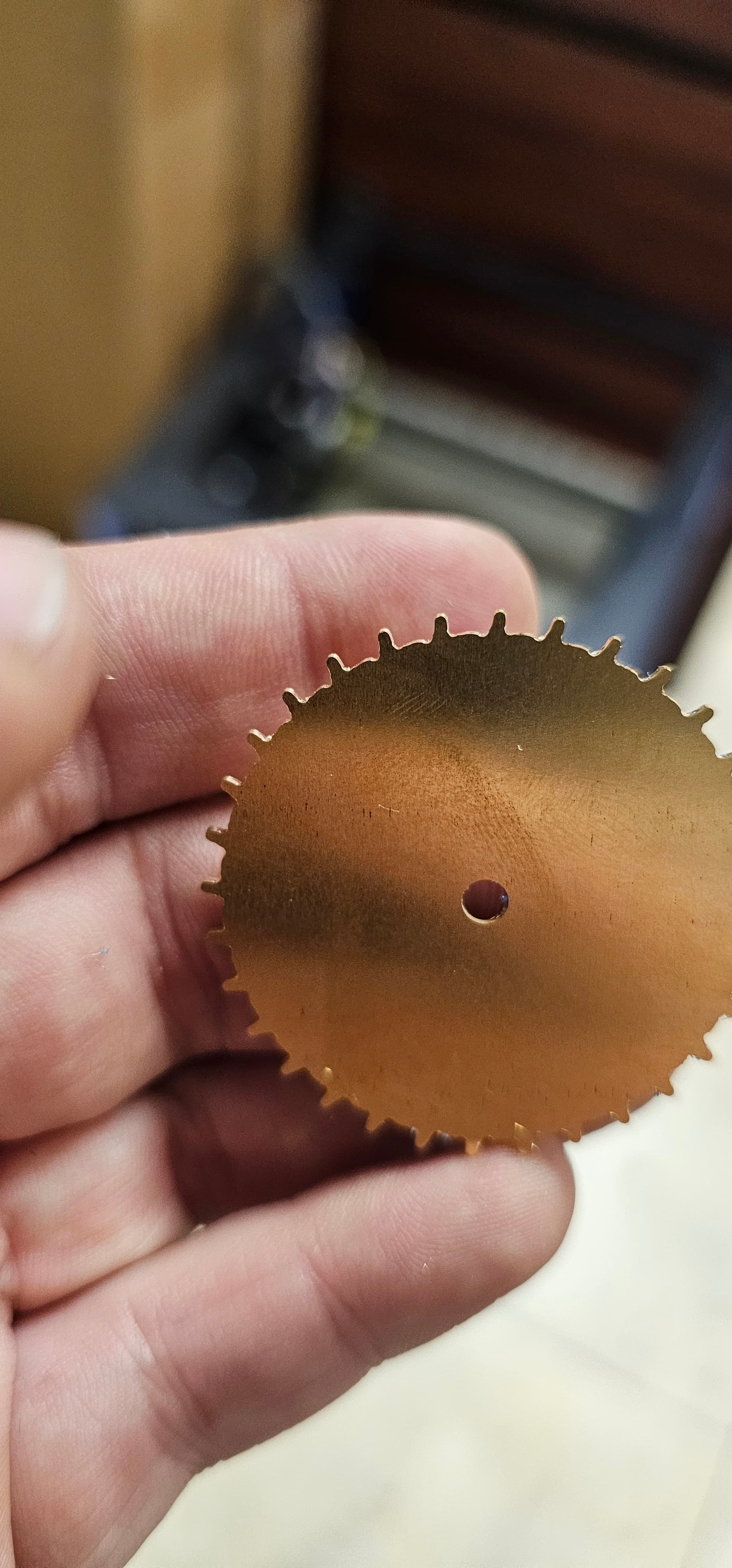
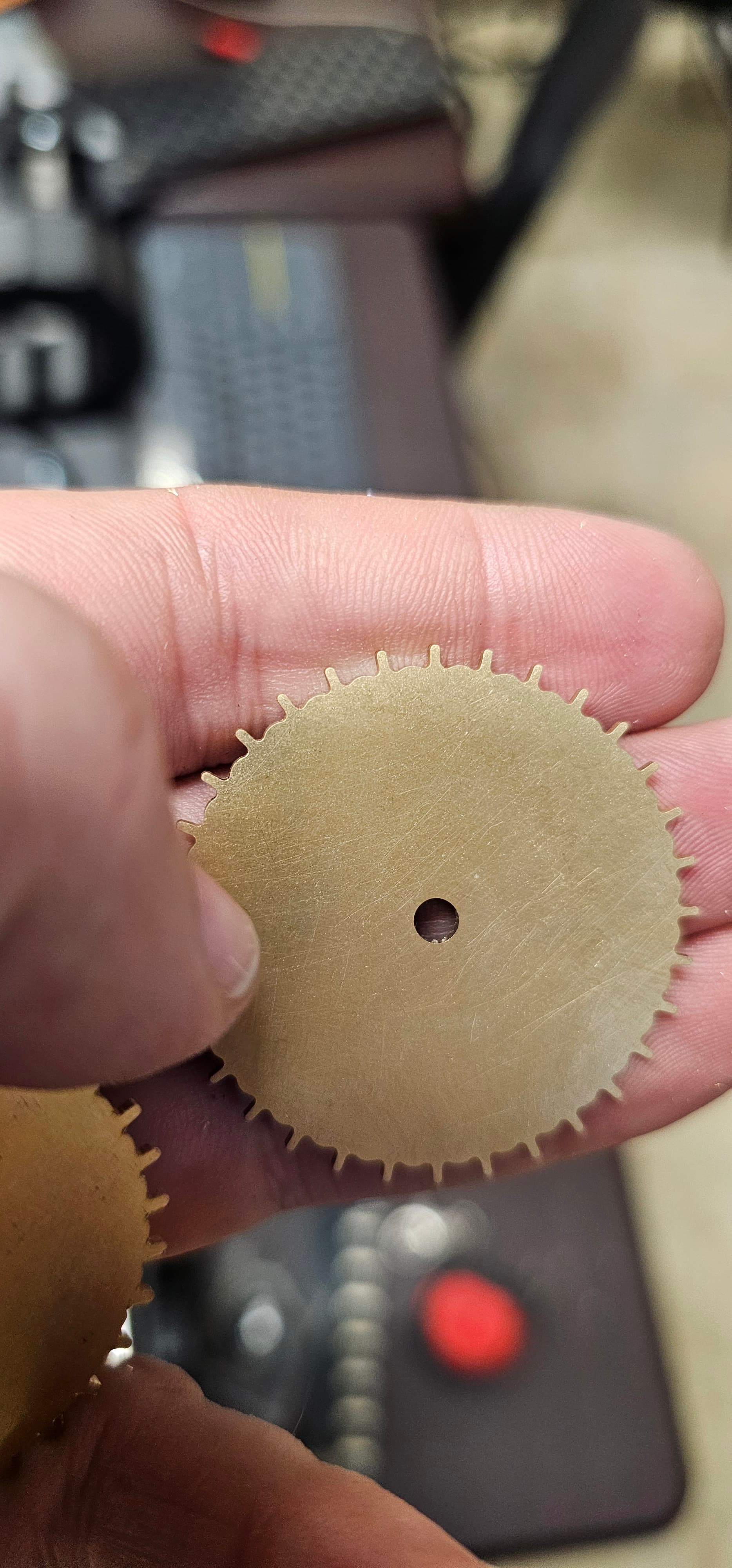
I added several 1/32 contours each with progressively smaller stock to leave (0.3, 0.2, 0.1, then 0) and the part came out with less of the “twist” to it but it is still there. When removing it I did notice something. The painters tape has a slight elasticity to it. So when forces are low like when I had the feedrate at 150mm and 32KRPM it did not move much. Now that I am up at 818mm the part is twisting. I am going to see if I can add some tabs to keep it attached to the parent stock till the very last operation.
Hard to tell what the cause would be just based on that. Once the piece can’t move out of the way the low flute volume of a steel cutter or high/low chipload due to runout might be an issue. Alternatively, it could also just be that the piece still isn’t rigid. If it’s flexing then it can flex back causing a sudden increase in chipload.
Anything notable in the cut before it broke? Where in the tool did it break?
I think to better understand this a dial indicator should be used with a carbide pin, a load applied using a game scale or something you can record or at least estimate the force, record deflection at 1-25lbs front to back and then side to side (WHILE POWERED ON) and if it is negligible enough then you know it probably isn’t the gantry.