I have been making brass indexing wheels for a Pick-N-Place system on my S5 Pro. My initial wheels had near perfect dimensions. I have to make 100 of these so went into production. After making the first 45 of them I decided to check my measurements. The cogs on the indexing wheel are supposed to be 0.9mm wide. They are coming out 0.7mm wide?!! The only thing I can think of that would cause this is that the endmill I am using for the last operation is too wide, but I was wondering if there is anything else I should check.
1 Like
Tool deflection because the tool/carriage/gantry is being pulled into the cut?
Could the stock be getting pulled into the cut?
What size tool is it? What cutting geometry?
Feeds and speeds? What sort of toolpath? In what CAM tool?
1 Like
doubt there is any pull strong enough to move the gantry but not strong enough to destroy a 1/32nd endmill. Losing steps is unlikely too.
Toolpath possible but unlikely given his experience. F/S would be more partial to sending the endmill to god. Maybe it was just ignored by QC, I’ve had tonnes of SPEtool endmills blatantly ignored eventhough they were burned during grinding and not cooled appropriately? Best guess would be to do a peck plunge deep enough to throw a 1/32nd gauge pin if you have them (also not a bad time to pickem up given your work)
Using Fusion360
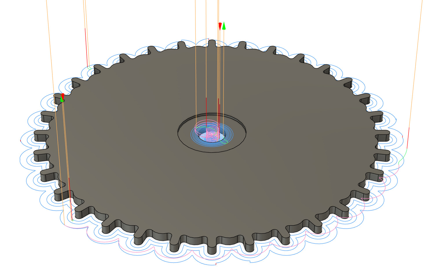
Tool is a SpeTool 1/32nd endmill 3 flute endmill doing a 2D contour. Previous op is using a 1/16th endmill with 0.1mm stock to leave.
Maybe tool engagement being at 50% is not giving it enough time to remove the material in the corners? Also effecting the leadout? would be super hard to identify without making a mating shape to between those teeth and seeing if one side or the other fails to match up rather than both.
If it’s both it’s probably the tool if it’s one its probably the toolpath
I appreciate the vote of confidence in my experience, but I have very little experience in metal or with tiny things. I have mostly been making large pieces out of plywood where 0.2mm is not even perceivable.
1 Like
I’d guess based on this spindle runout but it would be about 4 tenths out at 1" stickout which will be ridiculously hard to measure accurately and fix. I think I’ve got 5 tenths or so on mine. I’d also expect you to be breaking more endmills though, albeit carbide is strong as hell even with that amount of runout.
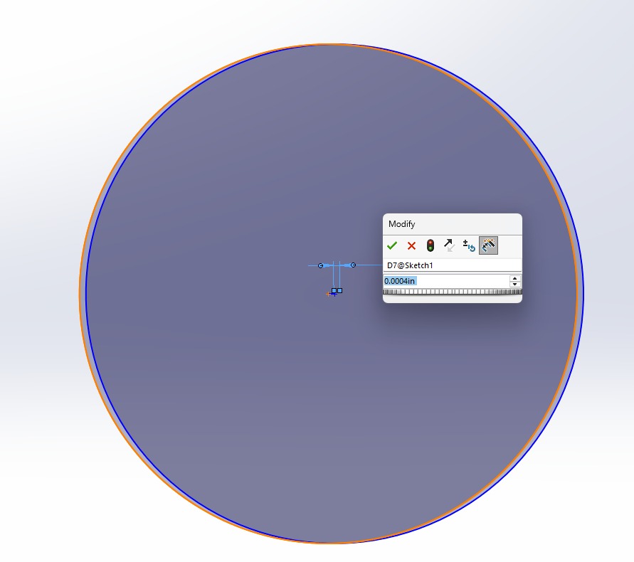
This should visualize how it’s just minor enough to not snap that endmill but your holes should be about 0.01602475" instead of .015625"
THAT SAID instead of fixing the runout if you are already having success with this endmill why not up it’s size to .01602475" in fusion and run the part again if you have the stock. If it comes up correctly we know the problem.
I should note that I used the https://map.harveyperformance.com/ tool from Harvey to get rough speeds and feeds to use in Brass based off similar Harvey tools. I know that they are not 100% equivalent figured it would get me in the ball park.
Would it make more sense to adjust the stock to leave instead?
Making your own huh, the beauty of a capable home shop ![]() (most folks I know would just get them cut out of fr4 from a board shop, no fun at all)
(most folks I know would just get them cut out of fr4 from a board shop, no fun at all)
I would probably start by backing off the stock to leave and sneaking up on the dimension. Though there may be some merit in adjusting the actual tool size if that’s the real issue.
I’d also second the issue with inconsistent sizing of spetools. At those sizes I’d recommend a reliable tool like Harvey or PreciseBits. (Or drillman1 on eBay if you’re on a budget. I’ve used their tools for years without a single problem)
Three flutes at that size also seems pretty sketchy in terms of chip evacuation. I usually run two flutes so I don’t have any real experience to say three would be a problem, it’s just a hunch.
What kind of brass are you running out of curiosity?
1 Like
H62 Brass
(extra words and stuff for the character limit)
1 Like
This. I won’t ever buy SPE cutters again. I think the shipping dept. mixes mm w/ inches and mis-lables stuff.
1 Like
Usual preface, I’m with PreciseBits so while I try to only post general information take everything I say with the understanding that I have a bias.
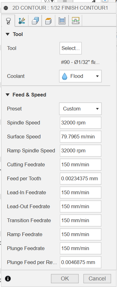
Assuming I understand this correctly you are taking a full depth cut of unknown depth with a more or less 0.1mm stepover at 32,000 RPM at 150mm/m… If that’s all correct you are burning the tool alive. That is definitely rubbing and you are almost certainly building up a edge even at that RPM. Then add dulling the tool on top of it and you are greatly increasing the force and therefore deflection with very little linear inches. Depending on the geometry, length of cut, and stickout of the tool you could EASILY get it to deflect enough to eat 0.2mm. That being said, if you are climb finishing than you would be deflecting away from your finished part and therefore it should get bigger. If you are conventional finishing than this could be your problem. Although there are some weird changes in this based on the stepover.
Even with Harvey’s in my opinion too low of chiploads, this is outside their range. From their own feed and speed sheet (Link) that tool would be:
- 500SFM (Over 61,000RPM)
- 0.00036" (0.009mm) chipload
- 0.093" (2.36mm) cutting depth
- 0.0025" (0.0635mm) stepover.
I’m assuming that you are maxed at your 32KRPM. So using that if you are going by their numbers you should be at 34.6IPM (879mm/m). Doesn’t look like you are going that full 3x axial so you can swap that for the radial. Although, you might not be able to maintain this in your direction changes (acceleration). So you would probably need to cut RPM and feed to keep it actually cutting at your programed feed.
Could also be runout, or tool diameter. But everything else aside you are starving the tool and that has consequences. If you do have any significant runout (relative to chipload) that’s going to make all this worse.
I’d take a stab at it but I don’t have enough information. I’d need to know the tool geometry (at a minimum the cutting length), how deep you are trying to go, if you can go in multiple passes, and hold down method. You also need to be taking enough chipload to compensate for your runout. So if you don’t have that I’d have to take a guess. So either runout, or spindle/router and collet source/grade. Even given all that this may not be possible to make a good cut with a 3 flute in this material. Probably going to have to sacrifice a lot of RPM to keep it at a reasonable feed to account for acceleration.
Hope that’s useful. Let me know if there’s something I can help with.
5 Likes
Material is 0.9mm thick. Here is the tool:
I was mistaken it is a 2 flute.
Helps that it’s a 2 flute. A steel cutter doesn’t though. Those are low rake, low flute volume, large edge radius tools. Not that you CAN’T use them for other things, just non-ideal.
If you are wanting me to take a crack at something I really do need the other data points. Just as a quick example if I gave you a 4 pass cut with a 0.01mm chipload that would fall apart if you had half that in runout. You’d end up sometimes cutting 0.005mm with it and that could kill you. To be clear. I’m NOT saying to try that, I’m just making up an example with a easy number. Would also be worthless if you needed it as a single pass.
Let me know.
1 Like
speaking of this they just shipped me an empty package and im fighting with amazon to receive my backup 1/16th downcut
I’m running the carbide 3D compact router and using their precision collets. I’m am doing a single pass at full DOC.
Oh I am running mist coolant too
My understanding is that collets are ~consumable. I’m not sure how they fail but if it’s a slow death I could see that as increased runout over time?
Which is to say, I’d recommend actually measuring your runout instead of taking any manufacturer provided numbers (especially so if it’s an older collet)
1 Like
That’s a tall order. I’ll try my best with this but I’m not sure it’s possible to get there.
So a bit of background. In most cases with a tool designed for non-ferrous metals in this size you can get down to around a 0.0003" (0076mm) chipload and not be rubbing. They will like higher numbers but that’s our floor. This is exacerbated in this case by the steel cutter design and runout. In order to actual cut and not grind away material we have to have a chip that’s at least bigger than the chip we are making. A steel cutter typically has a bigger edge radius to strengthen the edge. Runout gets added and subtracted from different flutes at different rotational positions, more so with a helix (flute twist). So we have to assume that we are going to both take a chip plus the runout and a chip minus the runout in each cut.
This is not meant as derogatory to the Makita or Makita clones. But one of the areas they are not great in is runout. There’s too steep of an angle with too little engagement length of the collet for consistent low runout. At a minimum I have to assume 0.0005" (0.013mm) runout regardless of collets. With customers we have tested with it’s a bit variable but it’s usually over double that.
So let’s assume that you have a really good router and collet with only 0.0005" (0.013mm) of runout. We’ll also assume an aggressive steel tool that we only have to hit a 0.0004" (0.010mm) chipload with. That would make our feed based on a 0.0009" (0.022mm) chipload and give us a big chip of 0.0014" (0.036mm) and a small chip of 0.0004" (0.010mm). If we convert that into a feed we get 54IPM (1371mm/m) with the 30K of the router. If we go down to the minimum of 12K we get 21.6IPM (549mm/m). But that’s only if we are taking at least a 50% of the tool diameter in radial (stepover). In the case of an 0.1mm cleanup pass we are only taking about 13%. So our actual chipload drops to 0.0006" (0.015mm). To compensate we need to increase our chipload up to ~0.00134" (0.034mm) to actually get our 0.0009" (0.022mm) programed feed. That works out to 80.5IPM (2045mm/m) at 30KRPM or 32.2IPM (818mm/m) at 12KRPM.
With those numbers there’s no way the machine will be able to keep up in that tight of a space with the 80.5IPM (2045mm/m). So our best bet is probably the 12KRPM at 32.2IPM (818mm/m). To be clear I can’t be sure that it will be able to maintain that feed either but we have much better odds there.
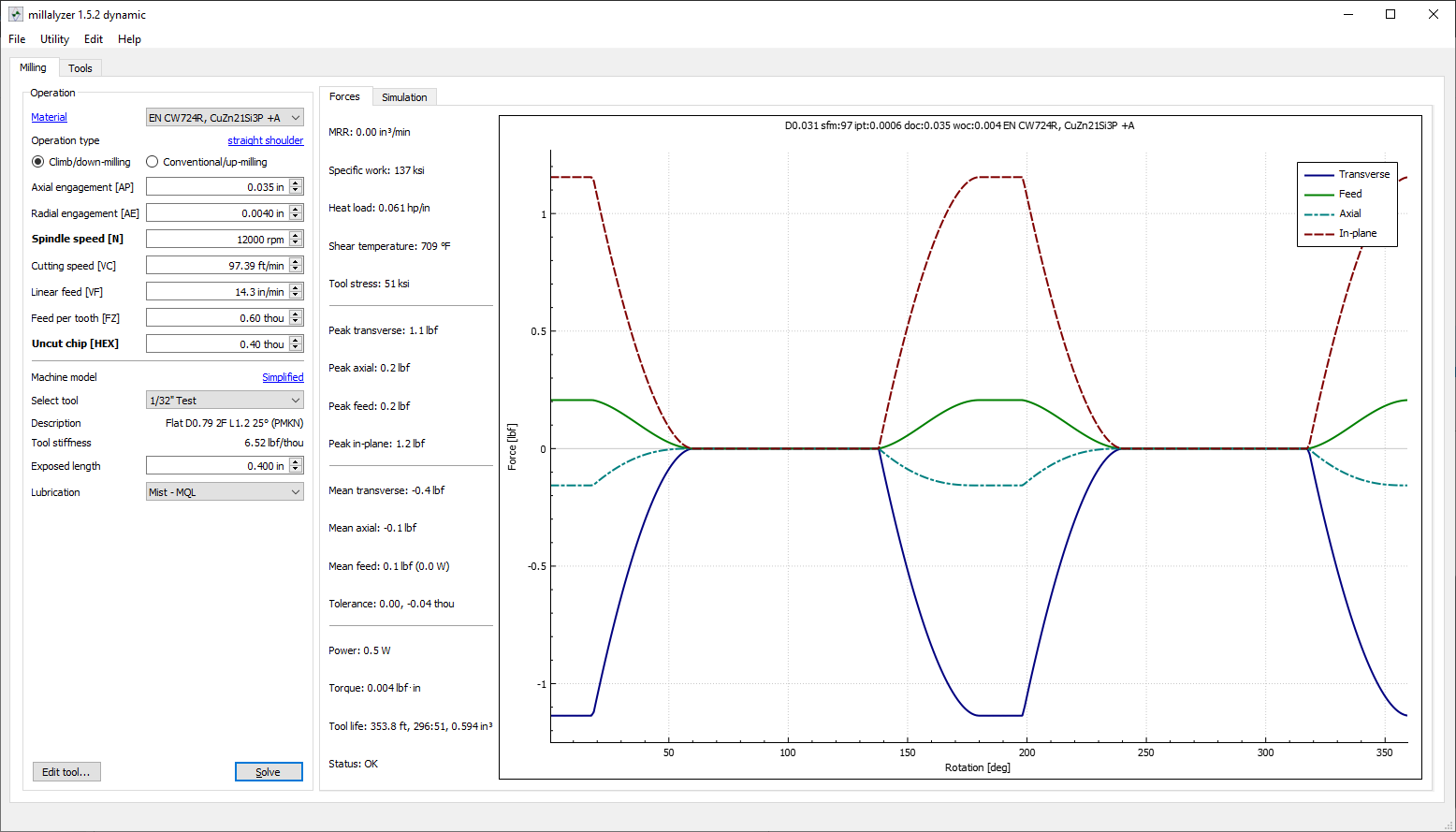
Let now look at Millalyzer to see if we are crazy. Have to use a silicon brass as it’s the closest thing there. Your H62 should be slightly easier on forces but want slightly more chipload.
Small chip:
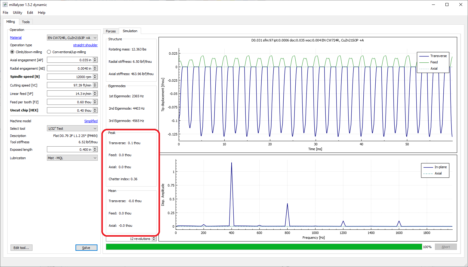
We are mostly ok here and we expect a peak deflection of 0.0001" (0.0025mm) into conventional.
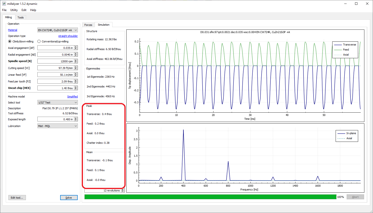
Large chip:
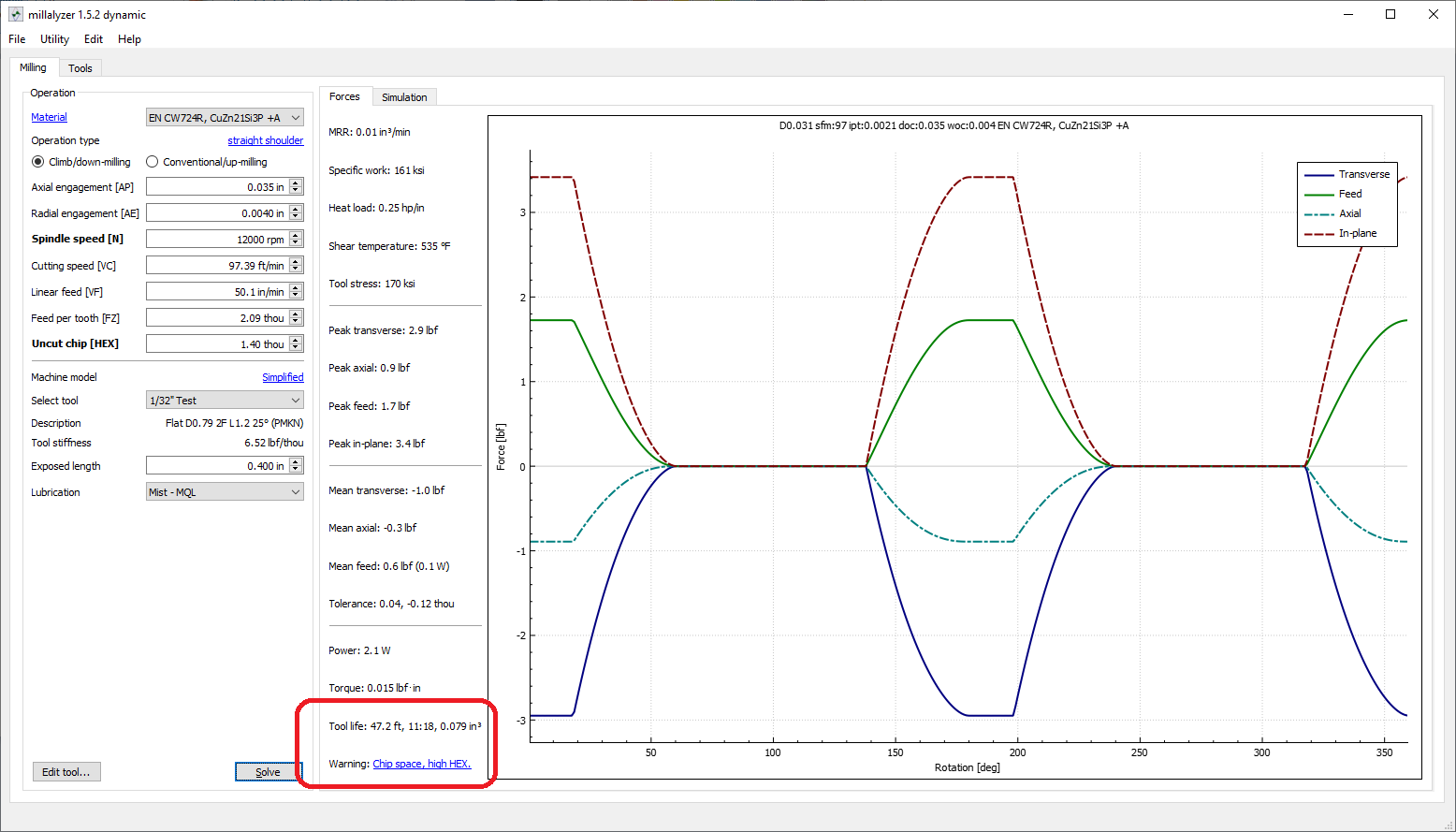
We do have some potential issues here. It’s warning us we might not have enough room in the flute of the cutter for the chips we are making. This being a steel cutter that may be true and we might compress them some. Might be ok as we are ejecting them out the back since this is a cleanup pass. Additionally, we won’t have this chipload across the whole flute as the helix will change the amount of runout across any single flute. Can’t say completely as I don’t have one of those cutters to inspect.
We have also increased the deflection on the tool up to 0.0004" (0.010mm).
If we have to assume for more runout we probably don’t have enough room to actually use the tool as a cutter. At least not with the steel cutter geometry and a full plunge. If you have to use the tool as a grinder you will actually have more forces and therefor more deflection even though you are removing less material. Keep in mind too that whatever your runout is will add to both sides of the cut.
Other solutions to this would be a single flute tool as they only have to deal with the runout in plunge and certain direction changes. Lower runout but that’s not an easy ask. A more aggressive cutter geometry to give us more space and a lower minimum chipload. Multiple passes to lower our forces and let us take larger chips.
All of the above is me assuming a lot. I used a fair generic steel geometry with a fairly aggressive edge radius just to make it work at all. If it’s a big blunt edged tool it will still grind as the edge can’t get under the chip.
Don’t know what kind of coolant you are using in the mist setup. If it’s a proper oil based one with a surfactant that will actually give you a smaller possible minimum chip. If it’s just a “chemical” fluid or alcohol/water that will just lower the temp. Though, those will let you use the tool as a grinder more without melting.
I hope that’s marginally useful. Let me know if you want me to expand on something or have any questions.
5 Likes
Coolant is just 50/50 IPA and distilled water.
I appreciate the in depth analysis. I will give 818 @ 12KRPM a try and cross my fingers.