There’s a reason that I started that with “my understanding is”. I don’t like the lack of data on it or the answers I get. Real world, in my experience it does play out that way. The minis do not require as much force to hold a tool in the same collet. Why it’s that way I still don’t have a good data backed answer for.
Now I’m going to do something stupid and go through some of what I’ve found where I don’t have conclusions or answers and could just straight out be misconstruing things. But maybe I’ll get some answers this way with more eyes on it. Worst case is I’ll look like an idiot…so nothing new.
Here’s what I do know. Like for like a smaller bolt with the same torque applied to it will result in more axial load. You can use the link you have there or this is a little easier to work with (Link). That doesn’t explain the differences though. Take the ER16 standard and mini nut as an example. If we throw those into the that calculator using the defaults other than lubrication to SAE 30 we get:
ER16M:
M19x1 18ft-lbs = 2406lbf clamping force
ER16:
M22x1.5 41fl-lbs = 4734lbf clamping force
Both of these don’t take into account the thread (they even say so).
Easiest free source I can find for this is an excerpt from Kyokuto Seisakusho on minsumi (Link). Not going to go through all of it but the functional part is:
Axial force = max yield percentage x tensile strength x effective sectional area (also called the Nominal Stress Area)
Again short version look here (Link) for the areas on course and fine thread. This doesn’t get us there completely as we don’t have those threads and pitches. But it’s enough to see that we aren’t going to pickup that much from the thread. Maybe around 10% more.
So now let’s go to MIL-HDBK-60 (Threaded Fasteners - Tightening to Proper Tension) - (Link)
We’re going to start by throwing all our numbers into a +/- 25% using a torque wrench on 6.1 table I. So that’s fun to start with… Then we get to the part that might matter 50.2 axial load applied talking about bolt elongation etc, etc. Then 100.2 where we talk about axial load related to thread helix and torque load.
I’m not going to pretend that I have gone through all this or understand it all. The short version that might be useful here is that the axial loads are relative to the elongation of the threads. Where functionally the the metal is stretched to create the load based on tensile strength, thread helix, modulus of elasticity, etc. Is that right? I don’t know, it’s on the back burner and the best I’ve been able to come up with in what little time I’ve had to spent on it. The problem with this is that I don’t really have a way of calculating it as we can’t use the bolt/screw numbers anymore as our mass isn’t even close to the same. We know it’s a lot less metal there (ER16 example again M-nut OD 22mm, standard nut 28mm). But the area the force is being applied to is still just the thread.
It would be nice to have a graph with X load on nut results in X clamping load on the tool. But those are few and far between and usually not sourced well. For those that want the one I have that’s still online (Link). Scroll down to clamping forces, short version, on an ER32 collet at 140Nm we get 20ish Nm on a 6mm tool.
If anyone has some other sources or some other way to calculate these or reasons why I should throw out any of the above I’d be grateful for the info.
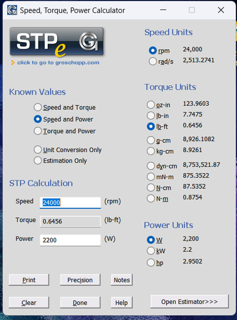
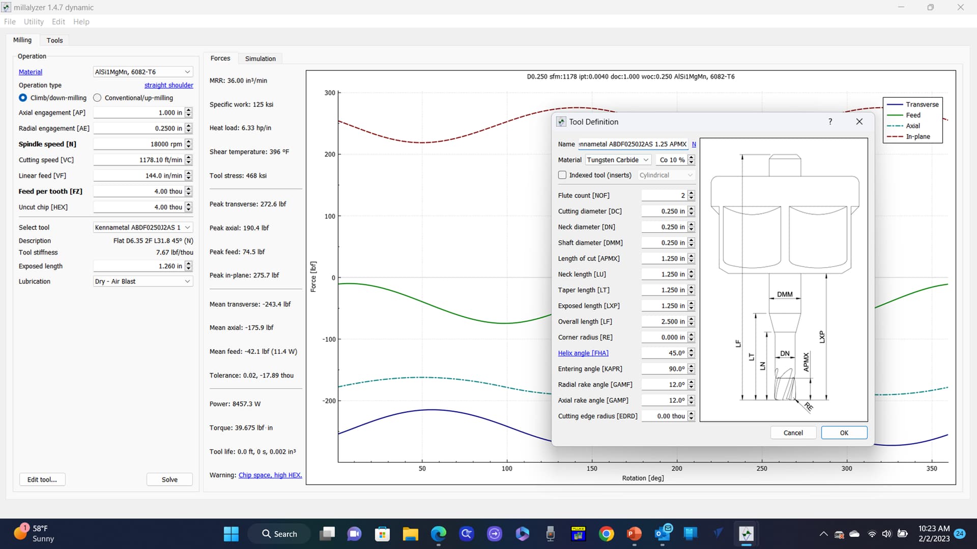
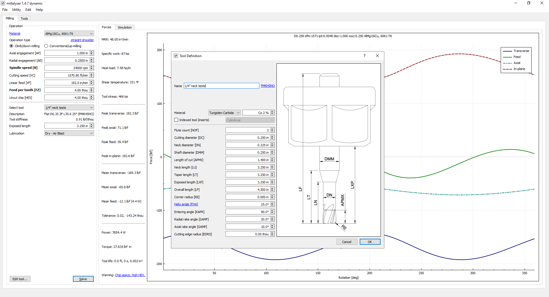
Short version to your follow up. Spindle torque doesn’t follow along with tool forces. e.g. here’s a mechatron 9hp spindle made for metal machining (Link). Torque tops out at under 6nm. The forces on even a 1/4" tool slotting 1" at a 0.004" chipload is over 60ft-lbs of axial force (depending on helix, rake, etc). No, the clamping force transferred to the tool is not 1 to 1 (see previous). From the data I have it gets closer the closer the bore diameter is to the collet diameter though. Still doesn’t matter for this as the clamping force isn’t a 1 to 1 to the collets ability to hold the tool in the collet.