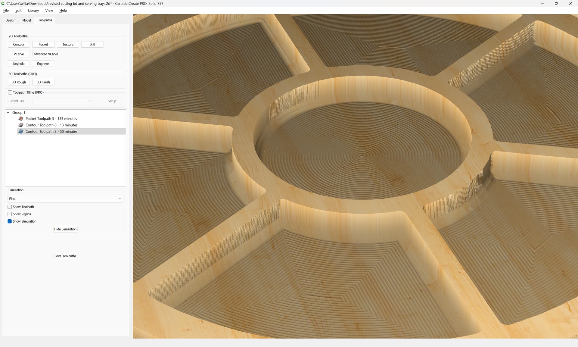
In the attached file, the “blue” straight line in each section of the tray is cutting about 1/16 or so deeper than the rest of the tray bottom. Why? It doesn’t show up in the design nor in the simulation.
revised cutting bd and serving tray.c2d (1004 KB)
Post a photo of how things cut?
You are pocketing with a ball-nosed tool — better to do this with a perimeter pass (for the rounding) and a square tool for the balance.
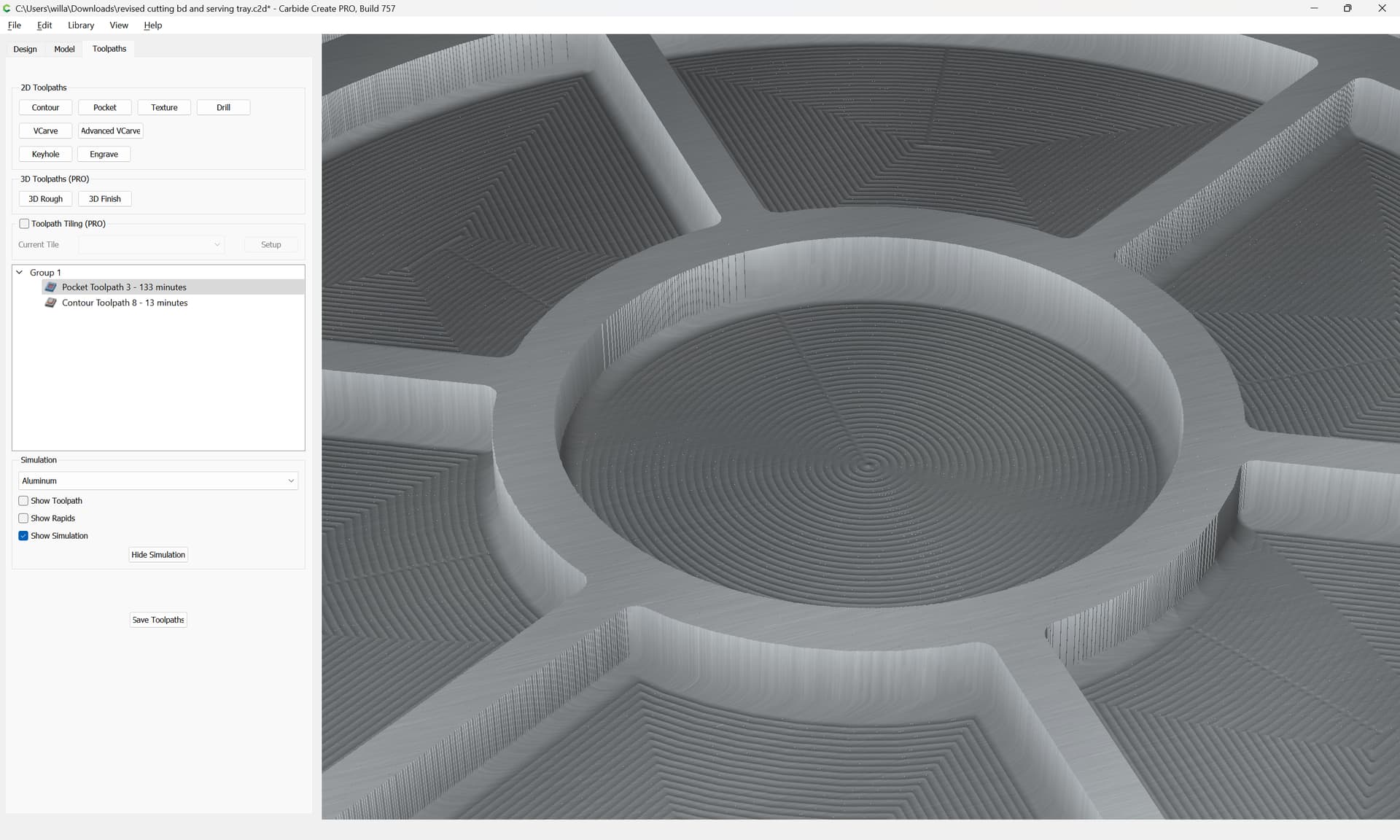
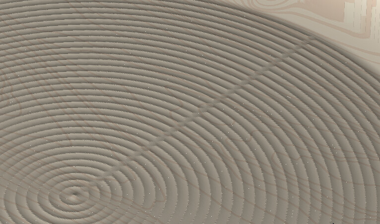
The lines do show if you angle the preview a bit:
If you want a smooth bottom see:
Otherwise, to achieve what you seem to want you will need to leave the bottoms uncut, then nest a series of geometries to which you will assign a No-offset contour:
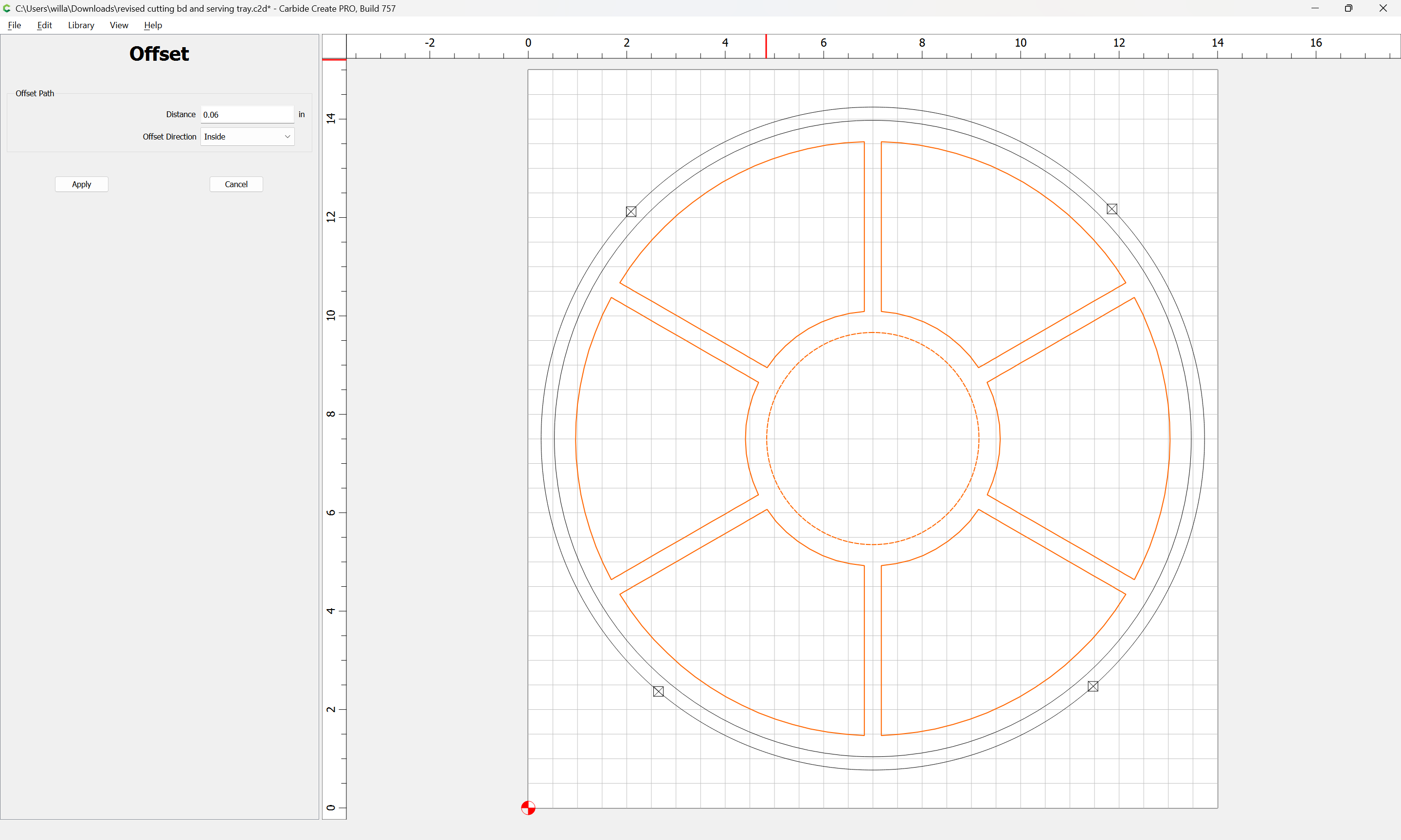

(adjusting the distance so as to arrive at an even distribution w/o a central point is left as an exercise for the reader)
Not sure I’m saying what the problem is. The “fine grooves” left by the ball mill are not the problem. In each tray section, in the toolpath view, not the simulation, there is what appears to be a solid straight blue line emanating from the center outwared in 4 of the sections and from the outside inward in the other two sections and the center circle.
These are not on the design and do not show up as a separate cut in simulation, but are cutting into each tray section. I don’t have my camera at the moment, and not sure it would show up anyway.
Again, not the individual stepovers, but the solid blue line showing in the toolpath view.
Thanks anyway.
I’ll just sand it out.
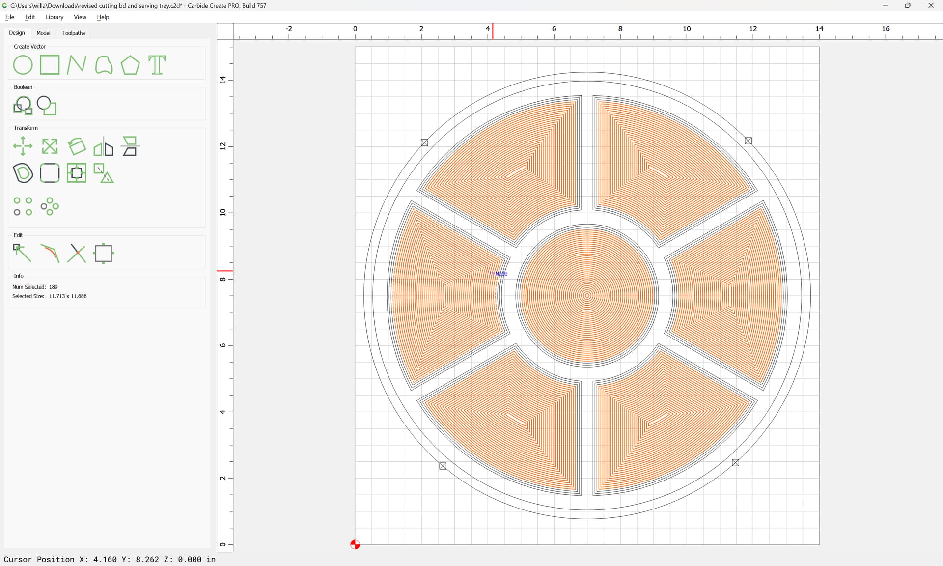
If you’re talking about these lines, they are the stepovers from one pass to the next.
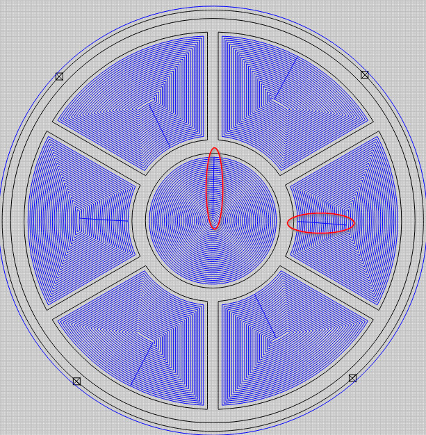
And they do show up in the simulation. They are not cutting any deeper, they are just cutting across the scallops left by the ballnose tool.
3 Likes
They are cutting deeper, by about 1/16". Not sure if I can make a pic show it up, but will try.
You are correct, I’ve never had a problem with those rapids, but this is defiantly different.
They should not be rapid moves, they should be cutting feedrate. And if they were cutting deeper, then that would mean the machine lost steps in the Z axis and the next pass would also be deeper.
They may 1/16" from the top of the scallops to the bottom of the stepover, but the bottom of the stepover & the bottom of each pass is your part surface, and they should be the same depth.
If you lay something straight, like a then scale or the edge of a piece of paper in the bottom of the scallop on one pass, so it crosses the stepover, the bottoms should line up.
2 Likes
That certainly should be the case.
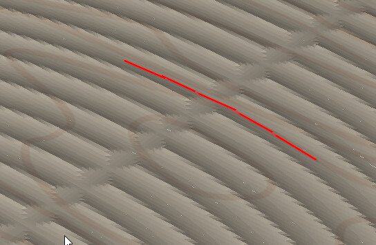
Attached is the best pic I can get to try and show the extra groove being cut. I have sanded out the concentric grooves made by the ball mill, but these grooves remain at now about 1/32"+ in each tray section.
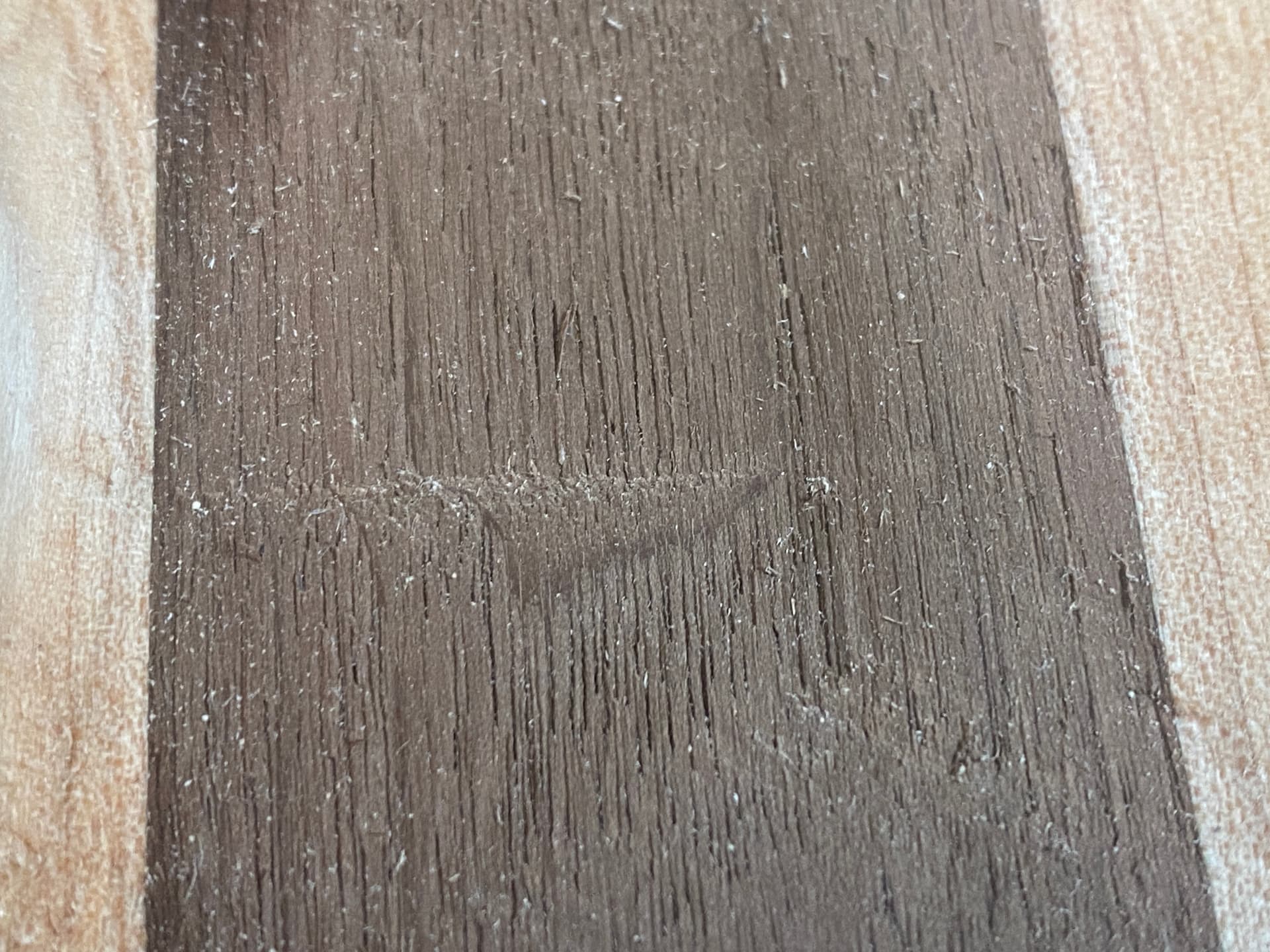
Wood is a natural material — that looks like tearout from a section which is aligned with, and caused by the movement transition.
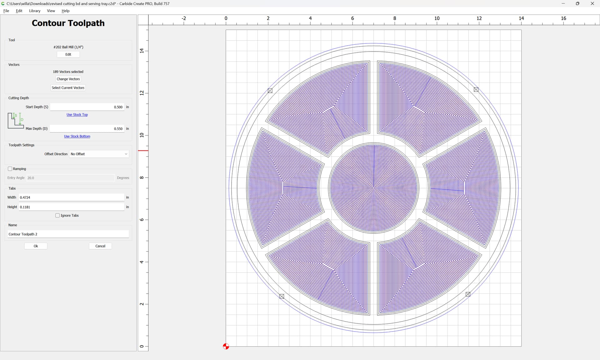
You may be able to address this by re-running a full-depth finishing pass, or adjusting the depth per pass —
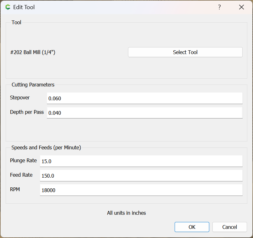
0.5 / 0.04 == 12.5
the machine is making 12 full depth passes at 0.04" and one final pass at 0.02"
0.5 / 13 == 0.0384615385
so if we set the depth per pass to 0.038
0.038 * 13 == 0.494
so 14 passes would be made, and the last pass would remove only 0.006" of material, resulting in a finishing pass, which if the defect was less than 0.044" should have effectively removed it.
Interesting that it might be tear out aligning with each tray section and exactly in the position of the blue line in the cut path. I have sanded it out, after an hour of 80/120 and while there is still a slight depression in each section, I’ll just tell them it is a “design” decision ![]()
I’m going to glue up another and try again. Not sure what will change, but will use a 1/4 end mill for the tray sections and then change to the ball mill and start just about the previous cut and get the "rounded"bottom.
Not sure it will change anything, but nothing ventured…
1 Like
Will:
You have always been very good with advise and while it makes no sense to me, I’ve glued up another maple/walnut/cherry cutting bd. and will try what you have suggested.
I must admit I can’t see how that would make it better, but again, nothing ventured …
Hopefully I can cut it tomorrow.
I agree with Tod1d. This seems normal because you are using a ball nose bit. If you were using a flat bit you wouldn’t see these. If you don’t want to see the concentric groves just use a flat end mill.
4 Likes
Well, cut another board with just a 1/4" end mill and everyone was right. Don’t understand why the ball mill does the extra groove, but that’s all for it. Threw it away. Don’t need all that extra work for sure to sand it out.
Thanks again for all the input.
1 Like
Don’t throw it away. The ball end mills are great for 3D work or edges where your want a rounded effect.
1 Like
This topic was automatically closed after 30 days. New replies are no longer allowed.