I’m working on a 2-sided project, which (for the sake of this discussion) resembles a top hat. With stock 26mm thick, I need to cut down about 20mm from one direction. But when I flip, I really only need to cut a few mm on the other side (under the “brim”). But in order to go through the whole process, I have ot let the roughing operation air-cut all the way down to 20mm, even though most of that is wasted.
Having the ability to set different depths (per side) for “Max Depth” in CM would give about 30% efficiency gain to my run time. Is this something that can be added easily?
I guess I can probably figure a way to export two completely separate “top-only” jobs with these different depths, but it seems risky for a flip job, since it’d be really easy to accidentally set a different parameter for the second job, and both the whole thing.
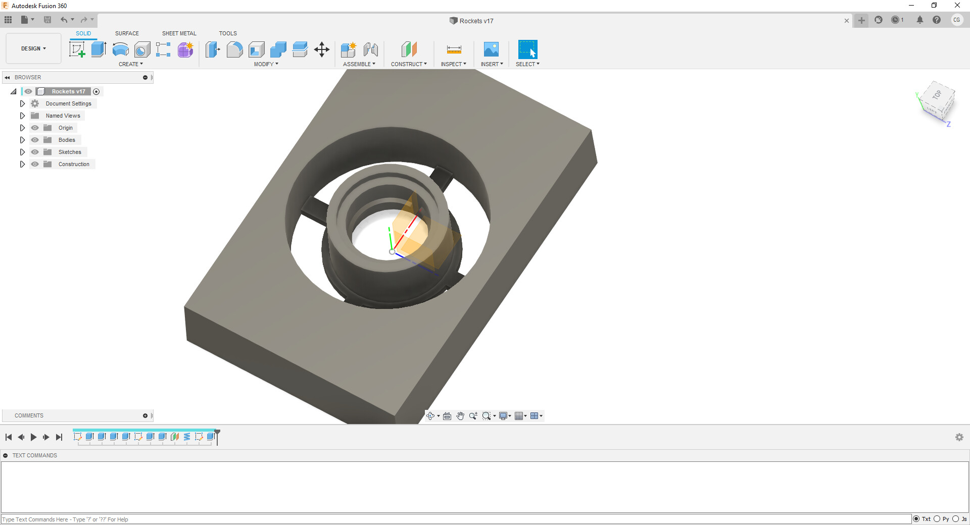
@WillAdams Here’s an example. The internal thread means I have to cut about 48% deep from both sides. But the inner rim around the bottom mean I need to cut 95% deep from the second side. But since CM only lets me set this depth once, I’m cutting to 95% from both sides, which is a waste of about 25%.
No - I’m saying that CM makes me cut 95% deep on both sides, even if I want to cut 95% on one side, and only 48% deep on the other.
I want to cut 48% deep on Side 1, and 95% deep on Side 2. But since I have to cut the same depth from both sides, Side 1 cuts way more than is needed, since I need Side 2 to cut so deep for just a few features.
Essentially, my “parting line” isn’t centered in the stock - it’s most of the way toward the bottom.
Put another way…
Suppose I want to cut out person’s face, with a flat back, positioned in the stock so that this flat face is 1mm from the bottom of the stock.
In this example, not a big deal, unless something makes you cut the flat side first (as in my case). If that happens, then the first cut not only flattens the back, but also cuts out the entire perimeter around the face, all the way through the depth of the stock, which is mostly wasted cutting. When you flip, the actual face is cut, overlapping most of the passes from the first side.
Carbide Motion cuts out the G-Code which is sent to it — why can’t you move this parting line in Fusion and make the G-Code there to match how you want the machine to move?
Sorry - I may have been obscuring the issue… I think it’s more a problem with MeshCAM than CM. That’s where the STL becomes G code. MeshCAM is the piece of the process that limits my Max Depth to be identical for both sides of the flip setup.
Will do - thanks. Sorry if I got off topic… I though MeshCAM was somewhat integrated with the rest of the tools used. I saw the “Carbide 3D License” and figured that it was a Carbide software package.
And thanks for the link. I’m exploring CAM in Fusion now, and will have to get it figured out. But it’s going to take me longer to learn than the hour of extra cutting happening now
Sort of, MeshCAM is bundled w/ Nomads, and developed by @robgrz who is one of the partners at Carbide 3D.
Please refer to support@grzsoftware.com for anything specific to MeshCAM, but check in w/ support@carbide3d.com for your Nomad and its software (aside from MeshCAM, and if you have a 3, Alibre).