As an old newbie, I am really liking CC in general. But I do have a major problem that prevents me from using it to do my first “real” job with my new Nomad. I want to engrave some text on an existing part.
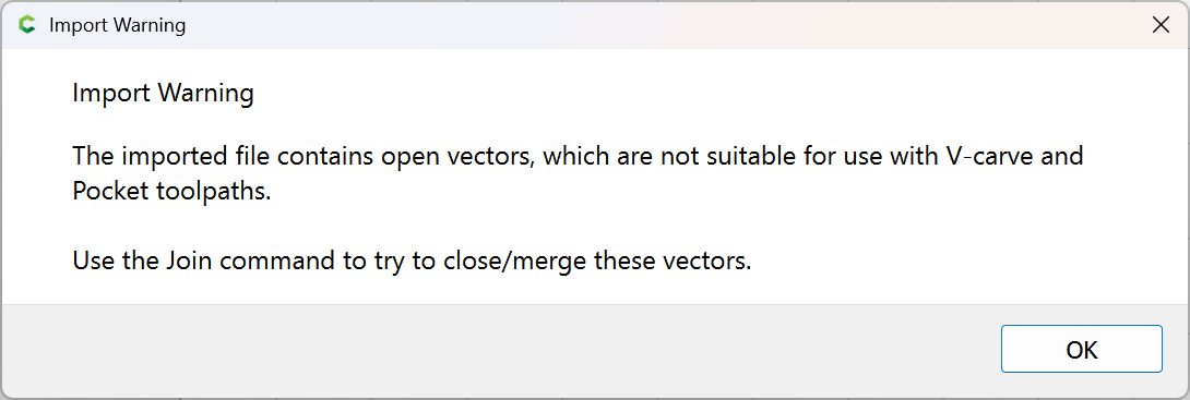
I know that this issue goes back at least a few years, but CC does not import DXF’s with arcs intact. But new day, new rev, new possibilities!
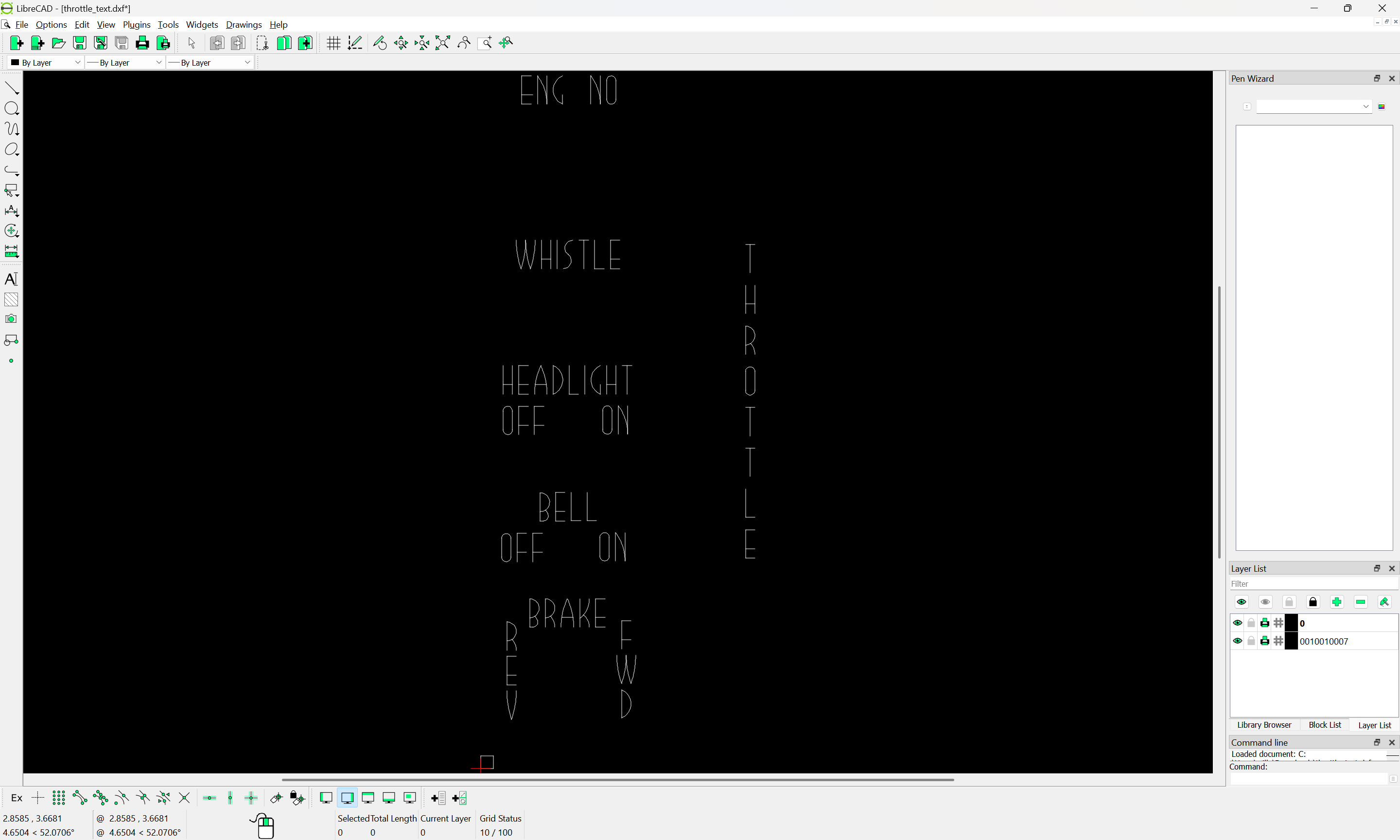
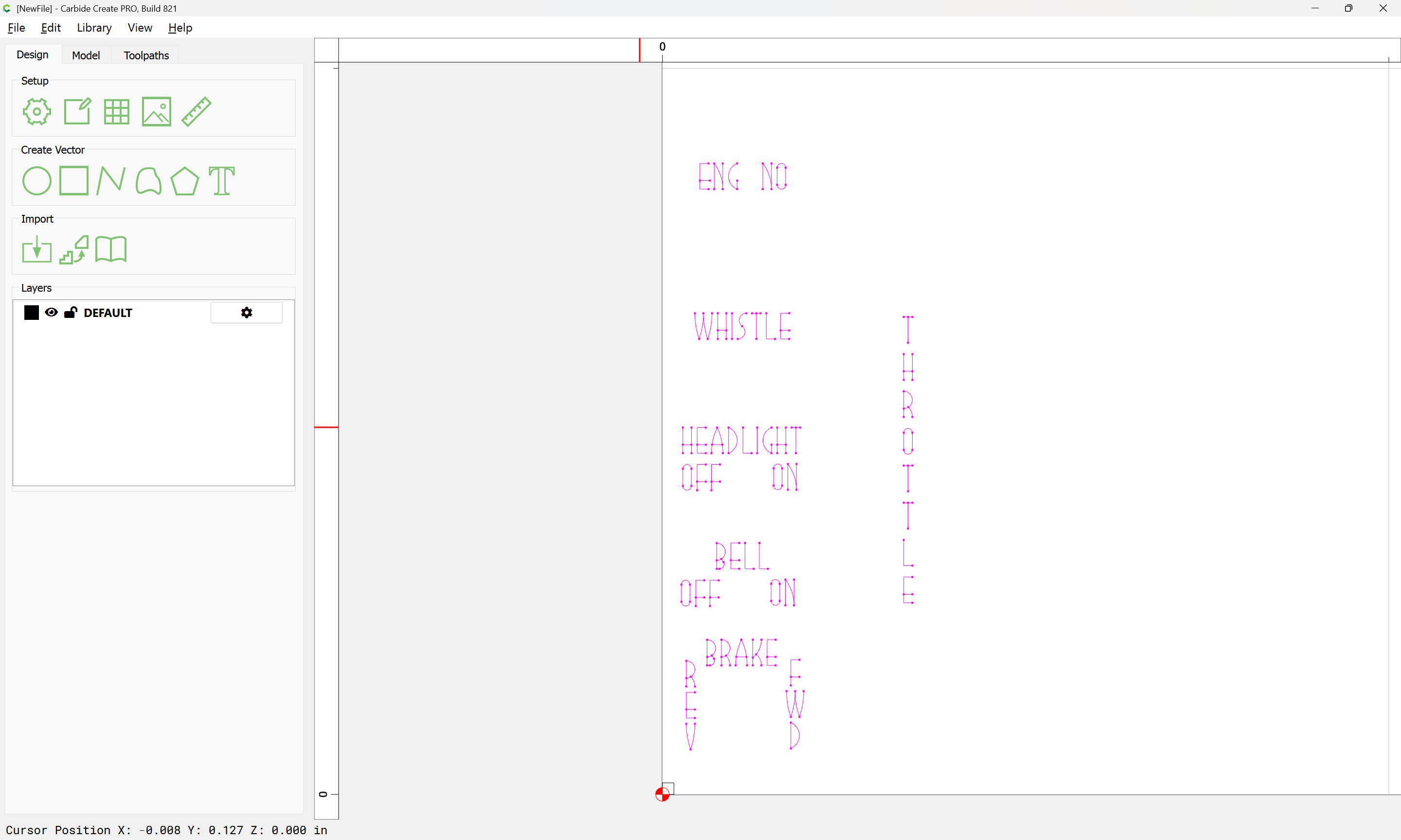
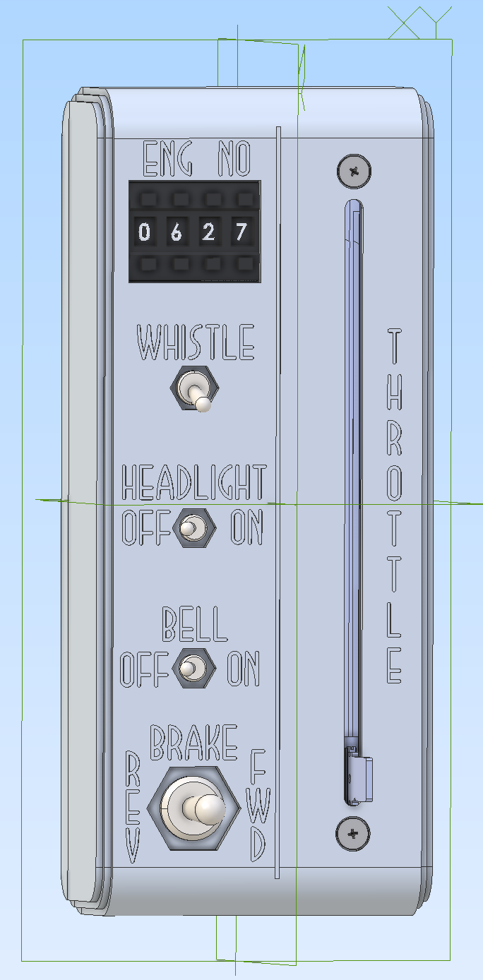
Please import the attached DXF with the arcs intact. I designed the single-stroke Art Deco font especially for the workpiece (a wireless model railroad DCC throttle) which I want to appear as a 1930’s artifact itself. It does not work with “polygon” arcs, much less the W which is rendered with straight lines.
Thank you Rob and team for any attention you can give this.
Plus why no G2/G3? CM handles arcs like a champ, going way way back.
BTW the little square in the southwest corner is there just to be able to align the DXF with part zero, because for the life of me I cannot export a DXF with a stable origin…
OK, per a suggestion in a similar thread from Will, I downloaded and installed LibreCad and washed the DXF through it. The LibreCad DXF does produce more nodes per arc than the native CAD file I uploaded above. I will make a test cut and see what it looks like in the Renshape… Thank you for all your help on the forum, @WillAdams
I machined the throttle case (without text) years ago, and am happy to be getting back to the project. Thanks again for your help. I still need to do a handle for the throttle slide pot. I may need to 3D print it because of the aspect ratio of the deep, narrow slot it will need.
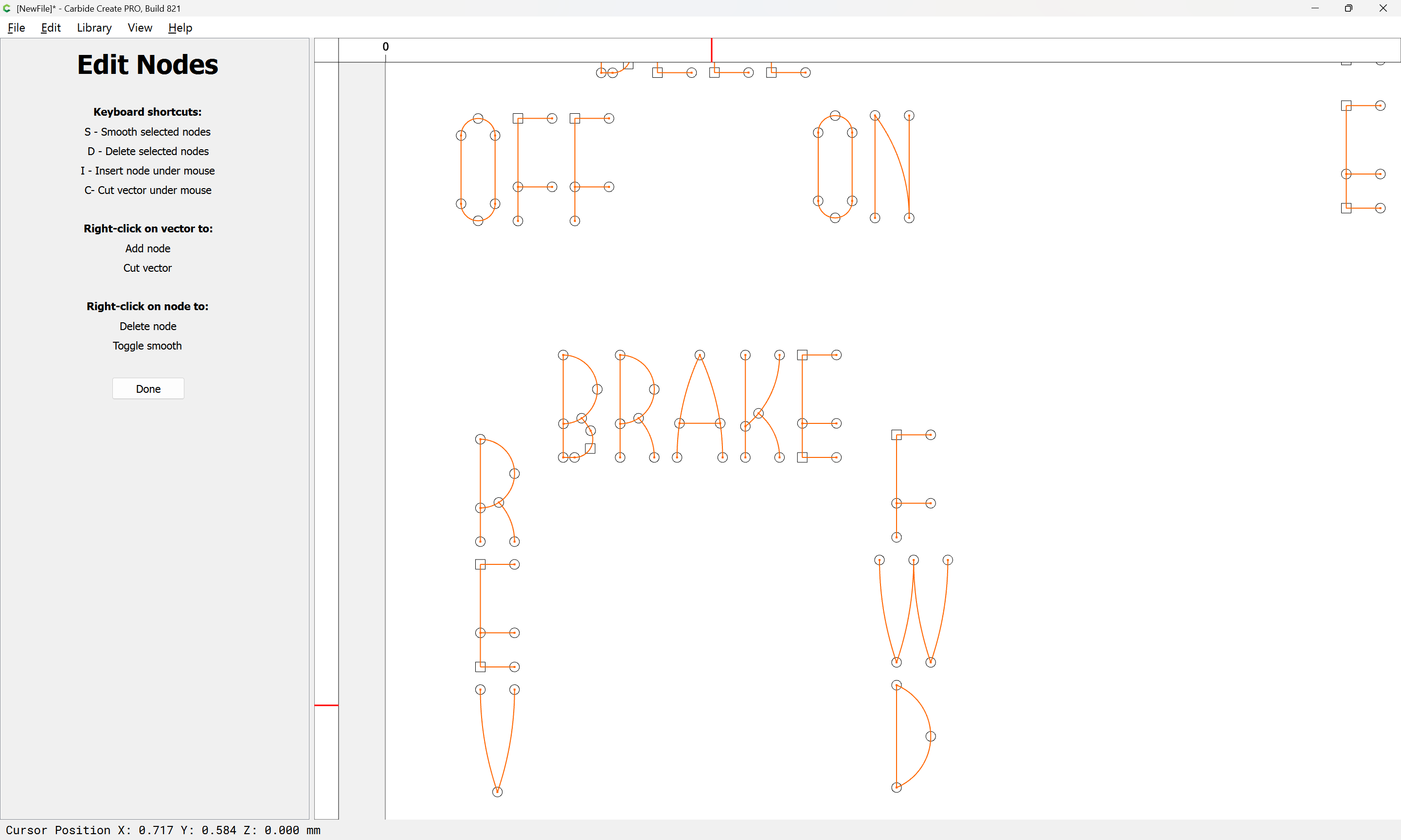
@WillAdams, how important is it to join things like the O and the W into single elements?
Thank you, Will. CC does seem to keep the cutter down in the material for “tail to head” adjacent elements now that I’ve looked more carefully at the simulation (aided by my first cup of coffee of the day…)
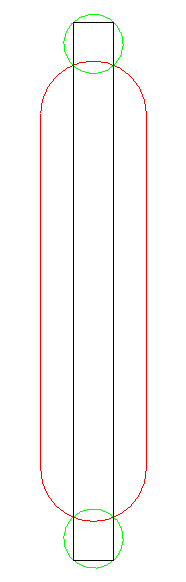
The black is the handle blade. The green are holes I would drill first. They don’t need to be as skinny as the blade. Then the red is a slot, which doesn’t need to be as skinny as the blade either. Where the blade touches the holes at its corners, plus the intersection between the holes and the slot, create contact points which should allow the handle to fit down over the blade and be located. A little Loctite and it should be secure. The operation forces, small as they are (this is for a slide pot, after all, and DJ’s operate 20 or 30 at a time with two fingers… ) are vertically in the plane of the paper.
Having a hard time understanding the holes needing to be drilled? Are they for the screw mounts based on the photo above?
It seems from your photo you just need the blade dimensions and 3D print out what you need for your style of handle. It seems I remember some style of T handle control we used to have.
Can you label the colors again?
Black = the actual controller “blade” which varies speed control
Green = Holes for what?
Red = Slot? The existing slot the bade to be in from the photo above?
My confusion may be that I think the “slot” is already machined into the throttle case?
Tim, the handle will be shaped like the BRAKE handle, just larger. Sorry for the “sketchiness” of my diagram. The diagram does represent the cavity machined into the handle to accept the slide pot’s blade.
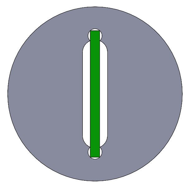
Here’s what a cross-section of the handle on the blade would look like
Blade is green and handle is gray. The drill holes and intersecting slot between them create the pocket for the blade. Both the drill diameter and endmill diameter can be larger than the blade, just as long as their location in the vertical axis is good and precise. The drilled holes are first so they don’t wander. The slotting endmill is larger enough in diameter that it shouldn’t wander (much…) when it hits the perimeter of the drilled holes. Any burrs raised might help the press-fit… [where’s the tongue-in-cheek emoticon?]
I do have silver colored PLA for my printer, but it wouldn’t be quite the same as machined and patinated aluminum to match the rest of the throttle assembly…
A picture is worth a thousand words, completely understand now. I didn’t realize you were illustrating the cross section of the handle itself.
Good thing with 3D printing is you can prototype the handle to ensure a tight fit. I would think you could print the ID of the handle to fit the OD of the blade. The current design although would fit tightly on the longitude of the blade it may wobble side to side if there is no contact points between the end circle cutouts. You could just replicate the circle cutouts along the length of the blade to shim it up. There will be allot of force on the handle/blade interface that we often don’t realize based on the fulcrum of the handle itself. Will this be a “T” handle or traditional “stick” handle?
I would still like to see the final product, I think the silver PLA will work fine.Add some grooves or ribs into the handle for effect.
Thank you, Tim. The handle will be a circular “bat” type of handle, like the bottom toggle switch handle, just larger.
Another option would be to 3D print a bushing that would fit over the blade and fit into a plain circular bore in the handle…
But first, I have some text to engrave! I can’t find my DTI from storage (I’m sure I put it somewhere really secure…) so I’ll need to figure out a different way to make sure my actual throttle cases are level when I go to engrave them. They might need some shimming to make them really level to the machine.
I found in my test cut, that it is really important, otherwise the cutter retracts at the end of each individual stroke rather than staying down in the material. Joining the elements lets the cutter stay down in the material. Even the B is able to be done in a single pass!