Feed Hold Switch

Different pins on the pro. They are different connectors.

2 Likes

Thanks!

Understand that C3D donā€™t want to publish wiring diagrams unless there are products sold by C3D due to responsibilityā€¦

That said, a simple standalone switch in a plastic box would have been a VERY valuable extra feature to be included in all future Pro shipments. With a breakout extension connector to enable future BitZero connection though.

1 Like

Is it common knowledge that the free hold button installation will do the following:

Pause the intialisation process, then restart it next time the free hold button is pressed.

After initialisation completes and itā€™s waiting for a bit to be installed, accidentally pressing the free hold button - not having done so up until this point - will start the BitSetter process going?

Thanks

Slight addendum:

While machiningā€¦
Feed Hold pauses.
Feed Hold again brings up the resume button on screen.
Hit on screen resume to continue.

Thanks, @SLCJedi

I knew about the ones youā€™ve mentioned and expected that to happen, but I wasnā€™t expecting the things I mentioned :thinking:

1 Like

Thanks Mr mingle for bringing up this subject :slight_smile:

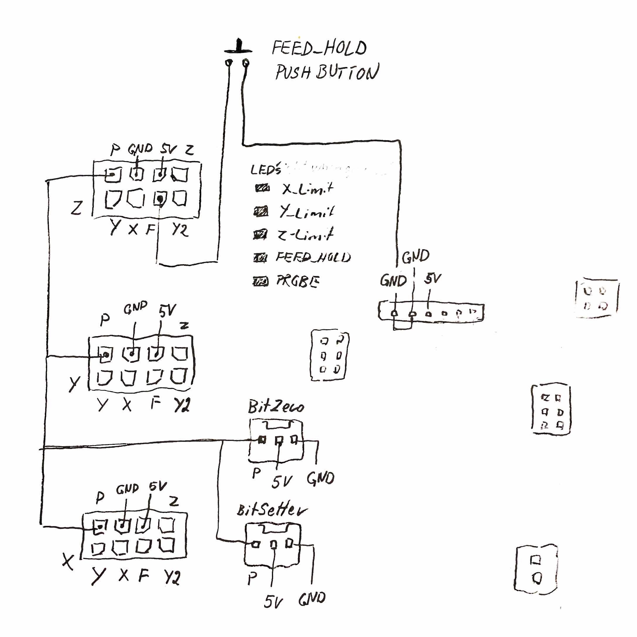
Multimeter says that the F signal is present on all X, Y, Z sensor input connectors. All signals seems to be mirrored on all connector and the individual wiring from each limit switch are using different pins except the Probe signal marked ā€œPā€. This is used both by the BitZero and the BitSetter.

This gave me a hint that if I ever, in the last minute, saw that Iā€™ve forgot to attach grounding clip to the mill and probing sequence had started, then I could always interrupt the sequence by pushing the Bitsetter button. Especially as first pass is for Z-axis. This knowledge has saved me a few times lately.

This connection scheme indicate that magnetic limit switches might be wired as open collector and that itĀ“s possible to add limit switches in both ends in the future. I am actually a bit surprised that there is no checkbox in carbide motion to make a kind of feed_stop during run if the CNC is trying to move outside the physical workspace.

FEED_HOLD is a ā€œmustā€ - and this is now tested on my Pro. It works :slight_smile: I havenĀ“t had time to test it throughly yet, but I think there might be some minor bugs if being used during in some stages of initialization procedure or in Probe mode. Need to check more.

Anyone having a clue about the Y2 signal?

My notes attached as I would really prefered to have this information first day myself. Board version 3.0b

4 Likes

As you have it wired, itā€™ll work as intended by the grbl firmware. Thereā€™s not much to it, you just need to connect that pin to ground as you are.

While interrupted in probe made for (Z, Y, X) it switched direction in the search for X after ā€œcontinueā€ (second push on feed HOLD).

Anything interesting on the bitrunner connector?

I guess I meant that there is nothing to the wiring. That does sound like an issue with Motionā€™s handling of things. It should not do that.

1 Like

DidnĀ“t go that far yet. Thought that C3D probably wouldnā€™t like me to do (or publish) too much reverse engineering. But I am sitting her wondering if the FUSE bits are set in the AVRĀ“sā€¦ Anyway, I donā€™t have time to go there (yet). ā€¦ unless the Bitrunners is out of stock for too long or if it doesnā€™t fit into my planning

1 Like

Itā€™s supposed to be available for sale within the next few weeks, according to sales. Going through final testing to make sure it works well with the new Pro electronics.

3 Likes

My V1 BitRunner works great on my Pro. :slight_smile: Iā€™m wondering what V2 will change.

1 Like

@SLCJedi @Julien
I checked out the link to the Quentacy switch, looks good, but I donā€™t necessarily need LED (and donā€™t want the task of figuring out how to power it) so my question is what are the necessary specifications of the momentary switch so I can find another? What specific requirements am I looking for?

I do DuPont connector/pin wiring all the time so the plug side will be no problemā€¦

If you donā€™t have the LEDā€¦ not much. Youā€™re just causing a momentary ground.

Right, the switch is normally open and closes on press, OFF-(ON) I think, correct?

The riser board has the 5V pin middle in between the left and right pins (connecting left and right sends to ground and activates feedhold), is there a switch like the one you posted that has LED that can run off that 5V? Would that be a safe thing to do (in terms of stress on the controller board)?

Iā€™m also reading the Definitive thread so bear with me, a lot to digestā€¦

The FeedHold pin is not a ā€œDupontā€ connector on the any versions of the main board. Make sure you use the correct connectors.
I donā€™t think youā€™d have issue with using the 5v for the LED, but itā€™ll just be dimmer if you use a 12v switch. For years, I used an extra limit switch.

2 Likes

@neilferreri
I realize Carbide uses the KK series by Molex, but the pins-to-connectors (the mating surface specifications) are identical to the DuPont pin used in every PC board. The KK series is expensive compared to generic PC/DuPont pins and connectors, I am ok with a higher chance of the plug getting accidentally pulled out (by not having the physical latching behavior of the KK series when plugged in).

Unless something has changed in the last 5 years, a square pin with 0.91mm diagonal, in 2.54mm pitch, is the specification for the DuPont pin and connector receptacle. That is the spacing and pin type on the riser board.

1 Like

@Norway So it looks like you connected a new wire to the z-switch in position F, and have added some wires to the GND area. Can you confirm this is where you have added the wires? Can you send me a picture of your control board with those wires and the parts that you used

Thinking this through, I think the average person may have a problem getting the new wire inserted and locked into the connectorā€¦ and if itā€™s in wrong, taking it out is a PITA. Also, possibly voids the warranty and you now have a connector with a non-oem wire attached to it.

Still working on a better solutionā€¦ I think I have one. (subject to some experimentation and testing.)

As far as powering the 12V LED in the PB from a 5V source? Not a good idea - LEDS arenā€™t like incandescent bulbs. At half the voltage they arenā€™t half as bright. Probably wonā€™t even light. In circuits that are used to dim LEDS, the dimming is controlled by a PWM dimmer, so the voltage is a constant 12V and the width of the pulse determines the amount of dim-ness (or brightness).

If the LED in the PB requires 12V, you just need to provide a wall wart 12V DC adapter to illuminate the PB. The PB listed above has separate wires for the LED and the pushbutton contacts. They donā€™t share a common ground, so that shouldnā€™t be an issue (as long as you donā€™t get the 12V source mixed up with the wires going to the CNC controller board.)

1 Like