@jmorgan So… where the heck is there an 8 pin connector on your Pro? I checked at the spindle end, and at the control board end… there are 2x2’s, 1x3’s… no 2x4’s.
greg,
if you look at mingle’s post of Jan 19th (above), the last picture clearly shows 3 of the 2x4 connectors in the middle of the board…can’t miss 'em!
ps. I just received a note from someone who bought one of my Pause Pro buttons… he was thrilled that he saved a slab of mahogany from disaster after a 2.5 hour job right near the end of the run…
Ahhh, I get it now. I thought the breakout connector was “outside” the enclosure hence why I looked for a 2x4 somewhere.

This has been a wonderful thread to read through. One question though, from what I understand the FH only needs a momentary switch closure to engage the ‘pause’. Does it matter if that connection was retained? For example if the button I had controlling it was a latching type, would it make any recourse if it stayed closed until I was ready to resolve the issue and unlatch the switch?
Basically a momentary PB is a better choice. Once you resolve the issue, you’re going to have to hit the PB a second time to enable the on-screen stop or resume buttons. The option to do that is only available once the Z hits it’s top position.
I suppose I should clarify my position. My intent is to have two buttons, one that is a dedicated FH momentary switch to act as you mentioned, but the second will be my emergency stop which will turn off thr router and engage FH. I know others wire the E-stop to cut power entirely to the whole system, but I don’t want to have that level of nuclear option. Killing the router and starting FH seem to be an equally safe way to abort the machine if need be, but the mushroom button will be latching.
Given what you’ve said, I could just use the normal FH button to perform the reengage sequence correct?
Scott:
ref: “Killing the router and starting FH seem to be an equally safe way to abort the machine if need be”
An opposing view: The E-Stop is intended for situations that might include the inability of the machine to respond to a FH command. In that case the need to cut power to the controller as well as the router would be needed.
Bill
1 Like
Great point Bill. Appreciate the wide point of view. 
If you connect your router to be controlled by the controller, a feedhold will turn off the router (assuming safety door is enabled).
EDIT: Looking back at your original question…I have tested the latching switch. It works fine. I used a SPDT latching-type switch (push button) and it worked as both a FeedHold and Resume. Having it connected, always, to one or the other didn’t cause any issues that I observed. My SO3 is in a constant state of being half updated, so I never fully installed that solution.
2 Likes
@greg5 where did you get the connectors?
Stephen:
For the connector I used one from an old PC case fan.
Bill
1 Like
They are Molex Microfit series, I got them from Digikey.
That’s how I have my machine set up. In addition to the FH button I have an E-stop that cuts power to both the controller and the spindle. The E-stop button is spliced into an extension cord which both are plugged into. The spindle is connected thru a vacuum switch which allows the vacuum to be powered from a separate circuit, this has the benefit of allowing the vacuum to continue running for a few seconds after the FH switch has been activated.
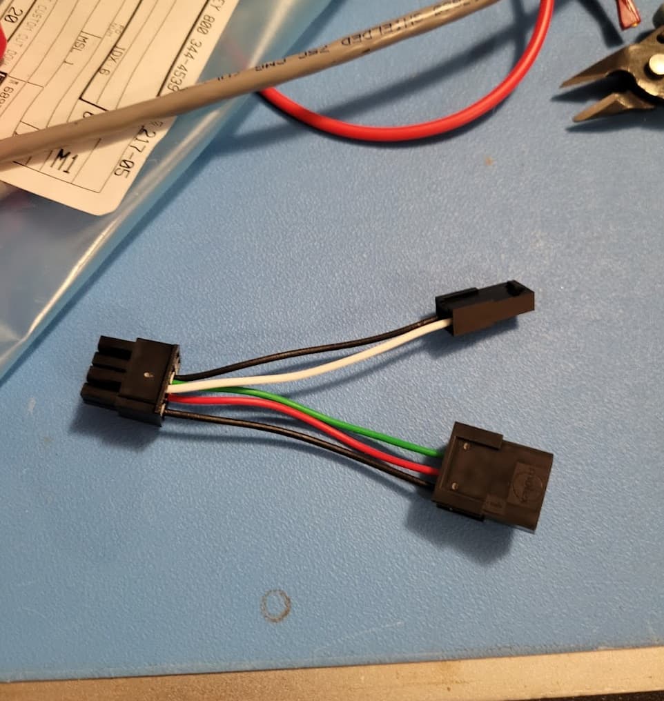
Some additional info that I shared in response to a message, didn’t realize at the time that I wasn’t responding to this thread, thought other folks may find it useful.
The parts I used were sourced from Amazon. The small connectors for the FH cable are 2.5mm pitch JST connectors. The bigger connectors are also from Amazon, Molex Micro-Fit 3.0 Dual Row (8 Circuits) Male & Female Receptacle Plug, w/Terminal sockets, (Pack of 1 Complete Set). I used a set of Iwiss SN-48B crimpers for both sets of pins. They aren’t an exact fit for the pins, but close enough. The extension cable for the switch itself is just some 2 conductor, 22AWG cable.
One note on the ground line, which needs to be split (Green in my photo). The Pins for the Molex connectors are too small to crimp onto two wires, so I just stripped a short section in the middle of the extension cable and soldered the shorter lead for the FH connectors to it. (I now notice that Greg5 appears to have been able to get two wires into one pin, perhaps he can share some tips on that)
I’ve been running a fair number of parts over the last month and the FH switch gets used on most jobs, often for cleaning chips out deeper pockets when running AL.