Just wrote up how to draw one up on the support e-mail.
Here’s a file to get folks started if they wish to make one:

Easy download link: [spoiler]Shapeoko CNC Router, Rigid, Accurate, Reliable, and Affordable
fidgetspinner.zip (1.3 KB)
Just wrote up how to draw one up on the support e-mail.
Here’s a file to get folks started if they wish to make one:
Easy download link: [spoiler]Shapeoko CNC Router, Rigid, Accurate, Reliable, and Affordable
fidgetspinner.zip (1.3 KB)
That said, a basic fidget spinner is straight-forward enough that one can make on in Carbide Create:
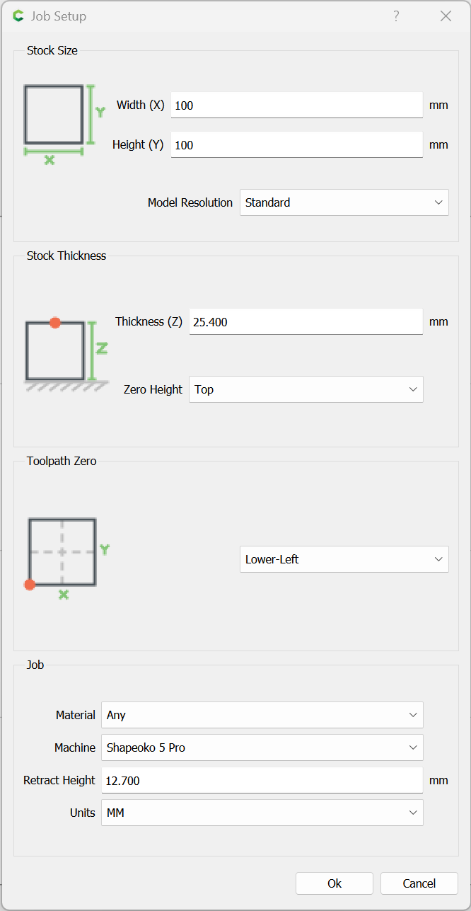
Job Setup
Metric is used since typical bearings (and the one used for this example) are measured in metric.
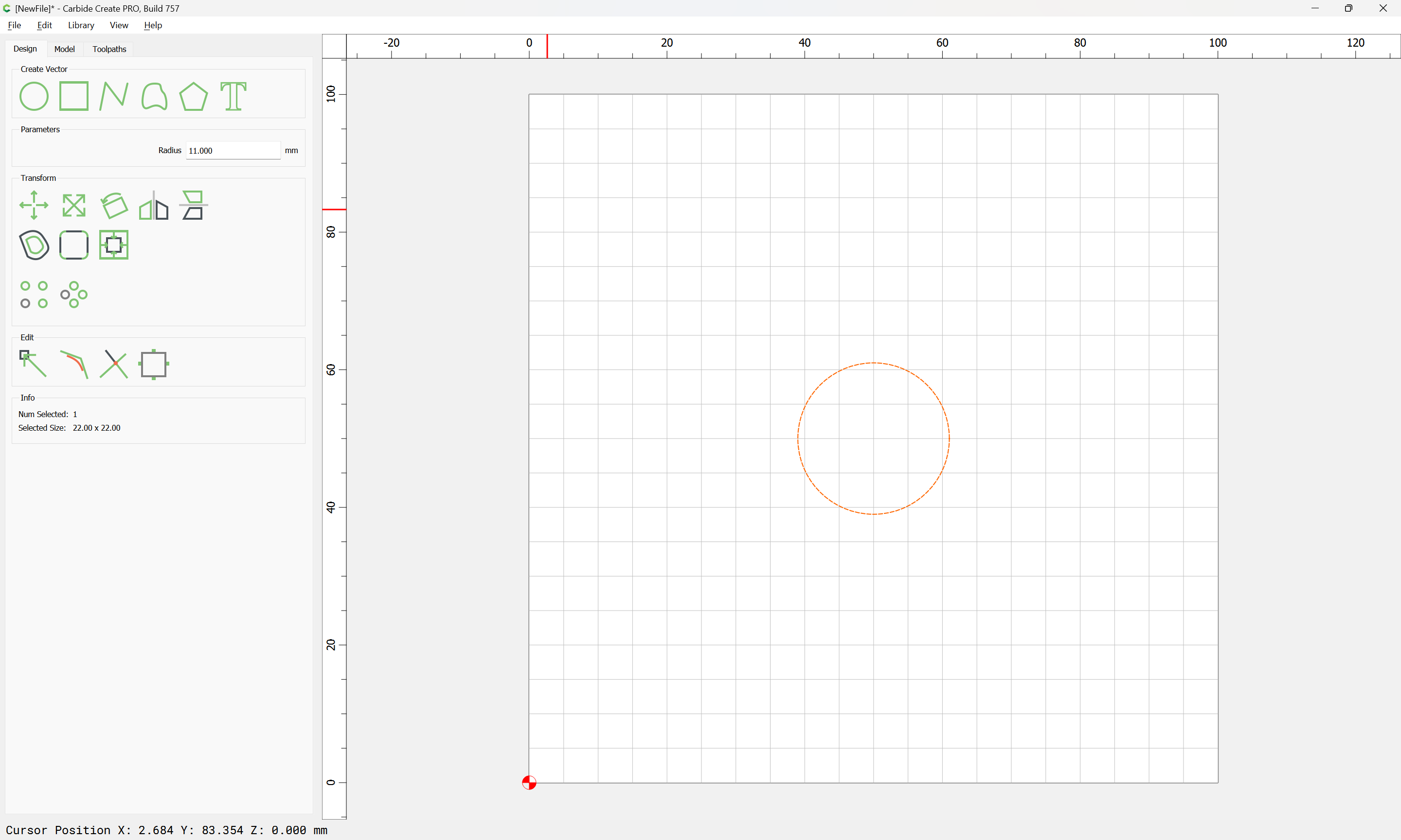
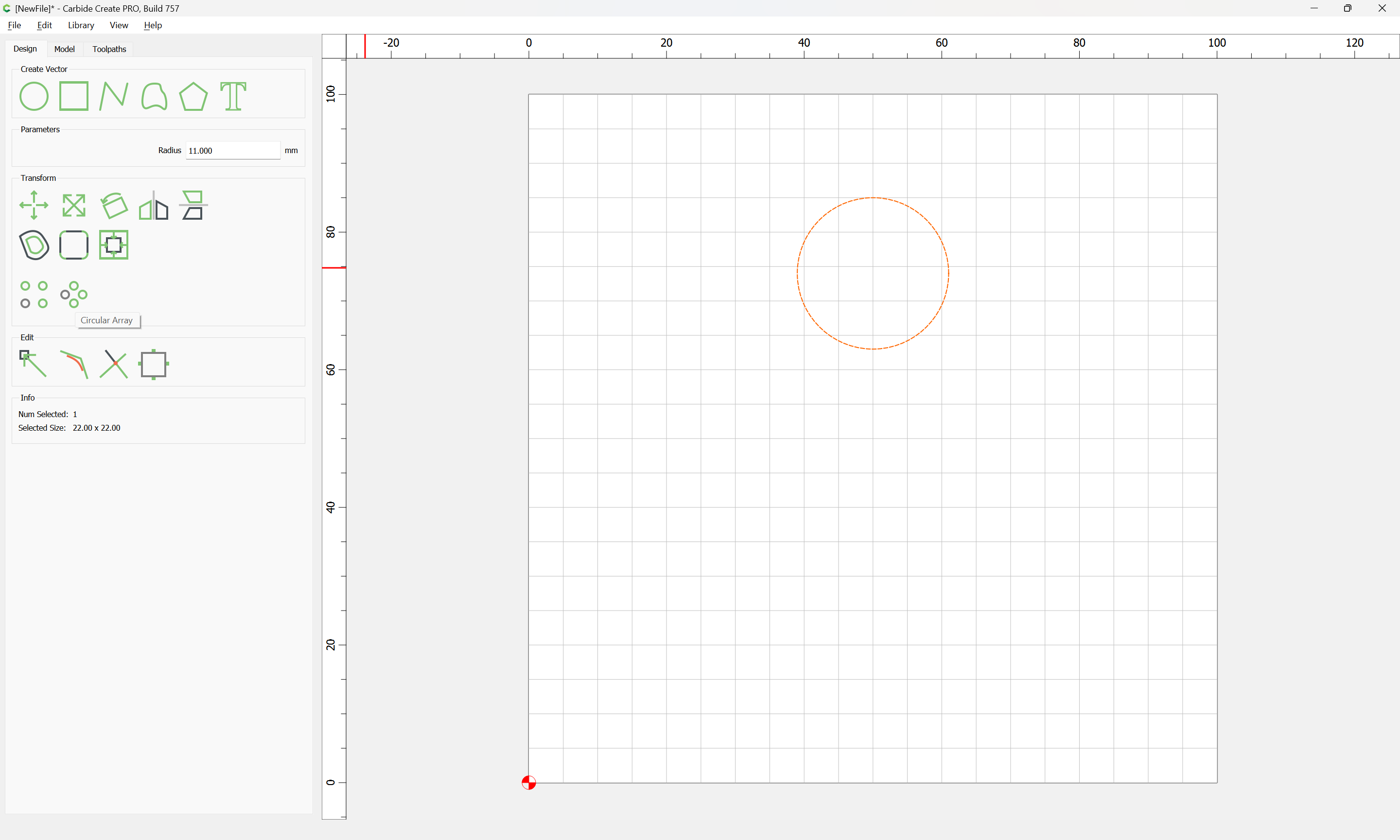
Start by going into design and drawing a circle at the center of the page. Change the radius to make a circle the diameter of a 608 bearing (11mm):
Originally the instructions were to use rotation to arrange things:
Copy the circle, and selecting the top or the bottom drag them into position so that they are placed along the vertical centerline and equidistant from the center:
Select the bottom-most circle, clone it (control/command c) and re-position the clone so as to be stacked on the original. Then rotate it 60 degrees about the center of the page:
repeat, but rotate -60 degrees around the center of the page.
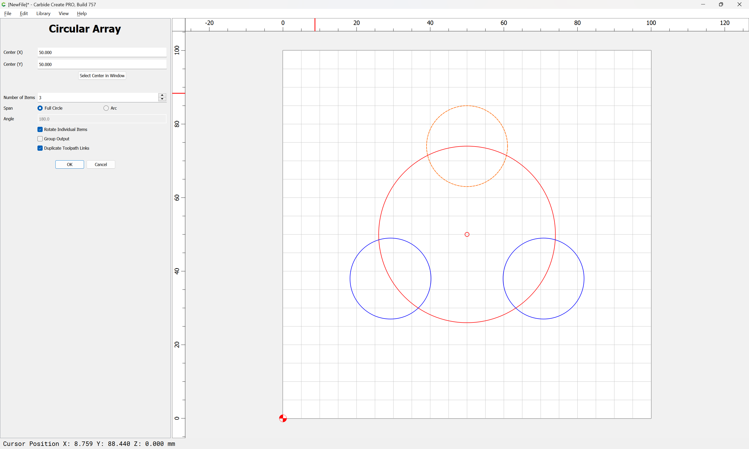
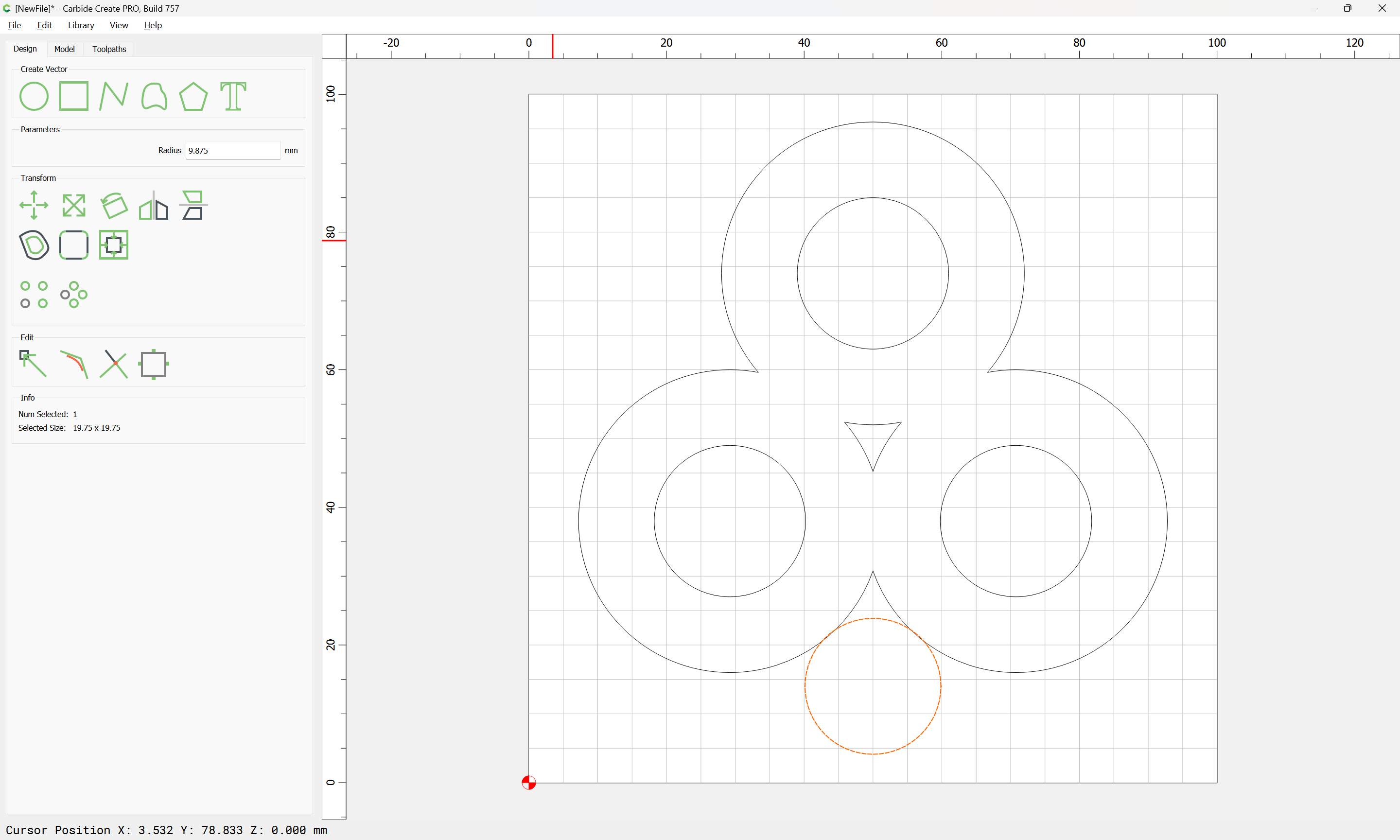
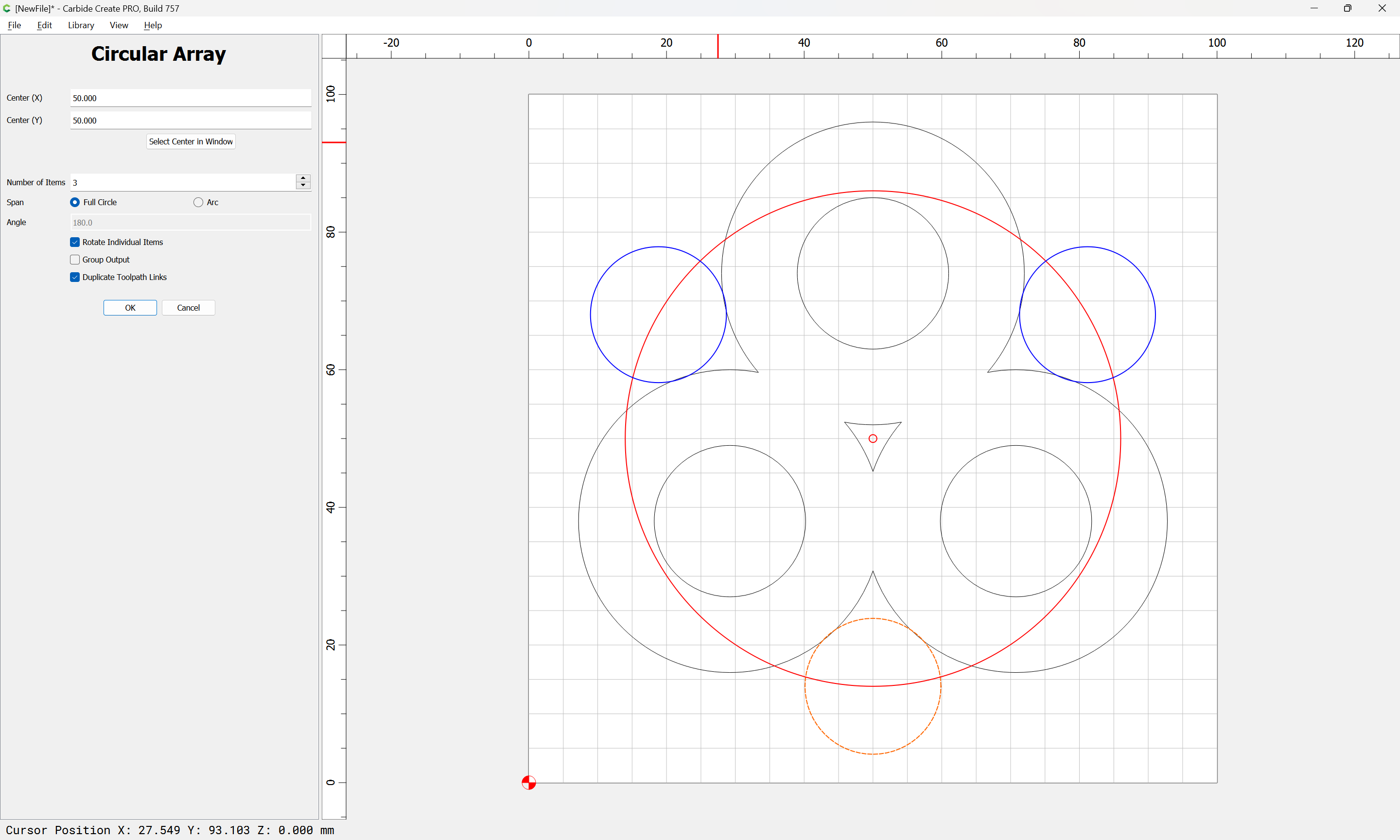
but the new Circular Array tool makes this much simpler — reposition the circle towards the top:
and use the Circular Array tool to make suitably placed circles:
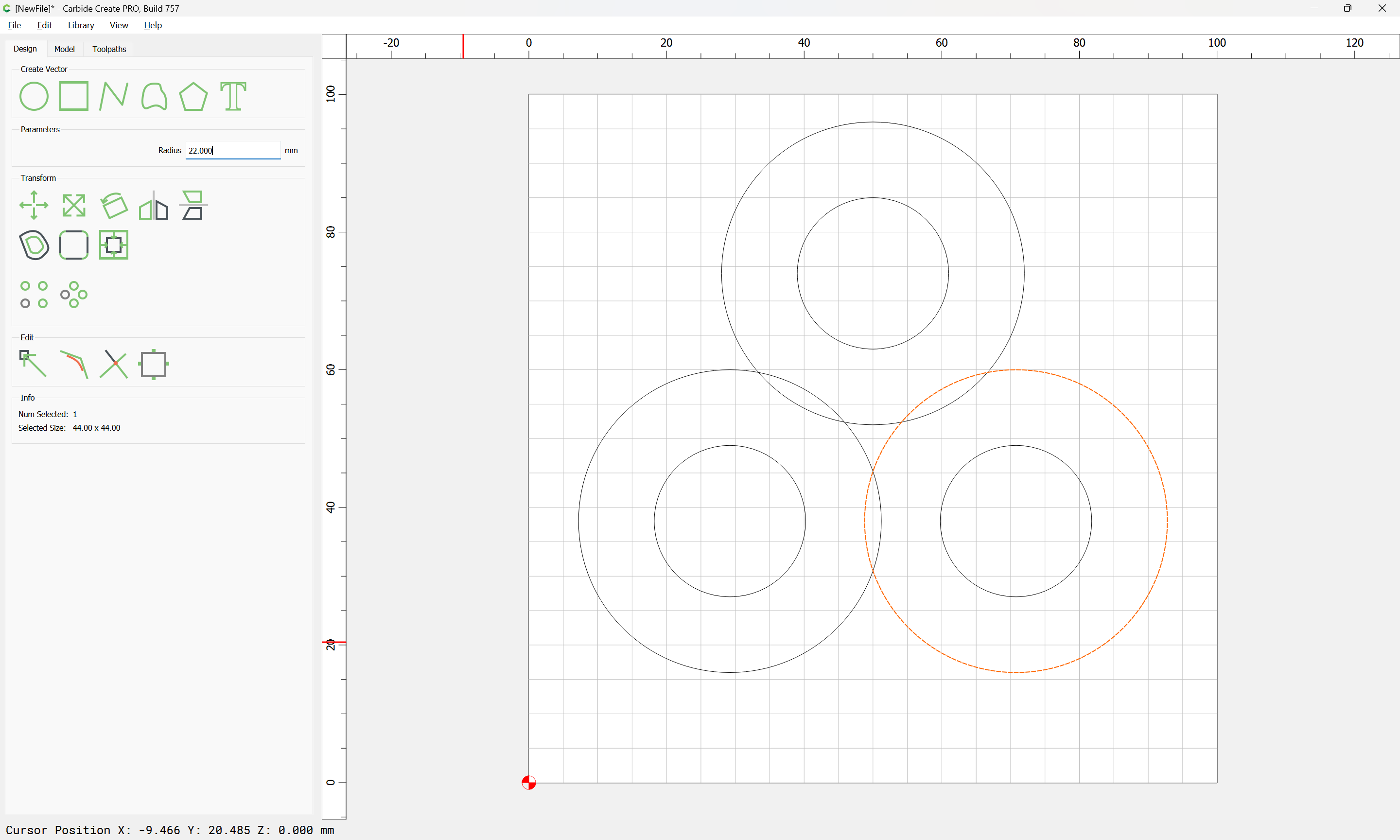
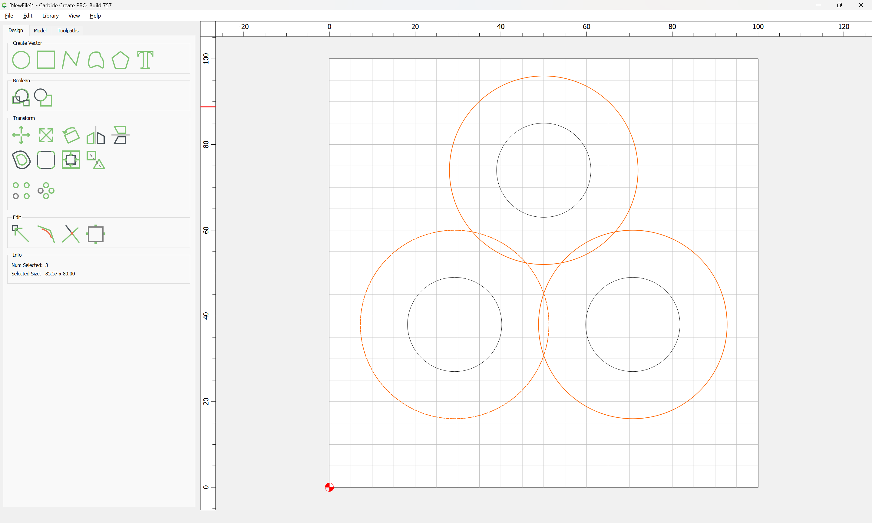
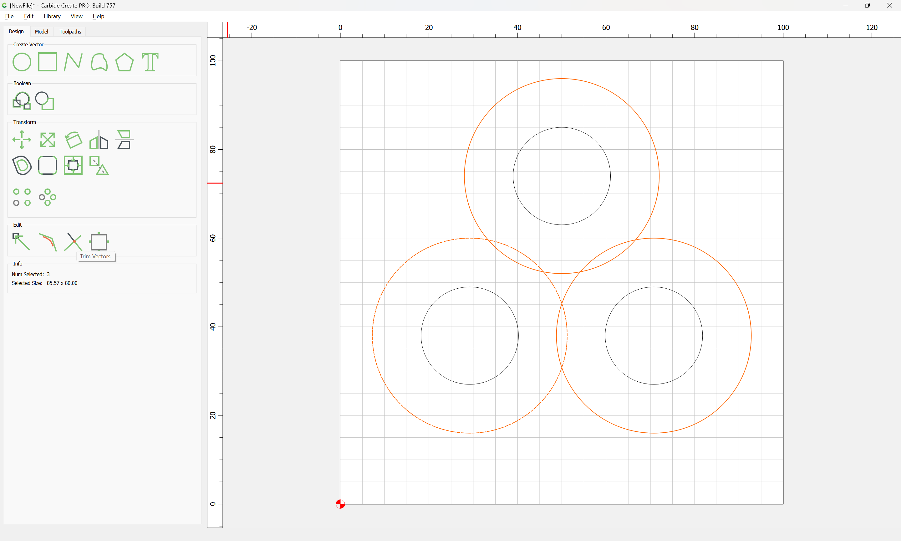
Select all the circles, then copy-paste them (or use the Duplicate feature) so that they are registered on top of the originals, then change the radius of the copies to 22mm or larger (so that they overlap):
One can either use Boolean Union to join the outer circles:
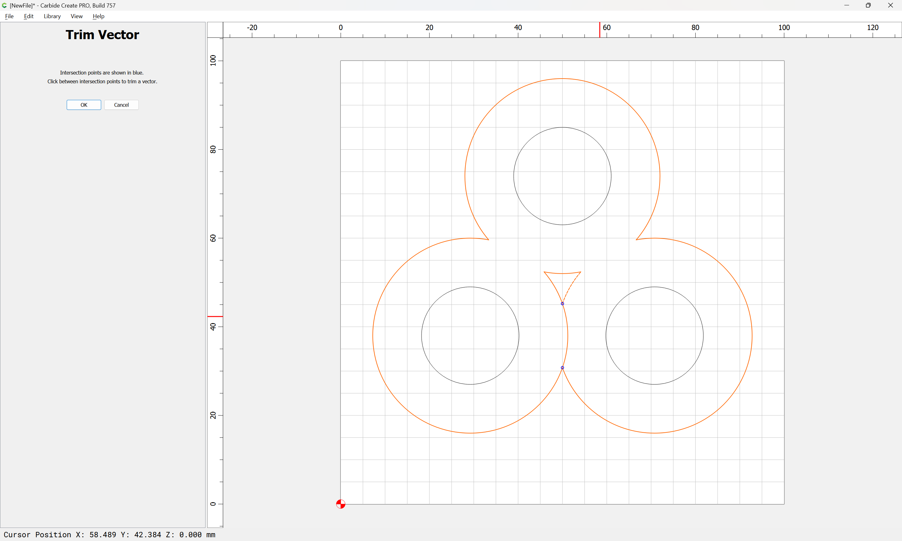
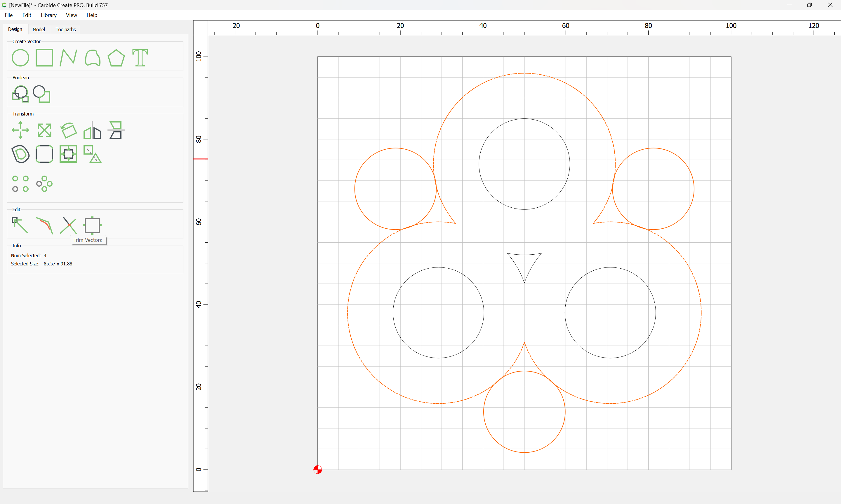
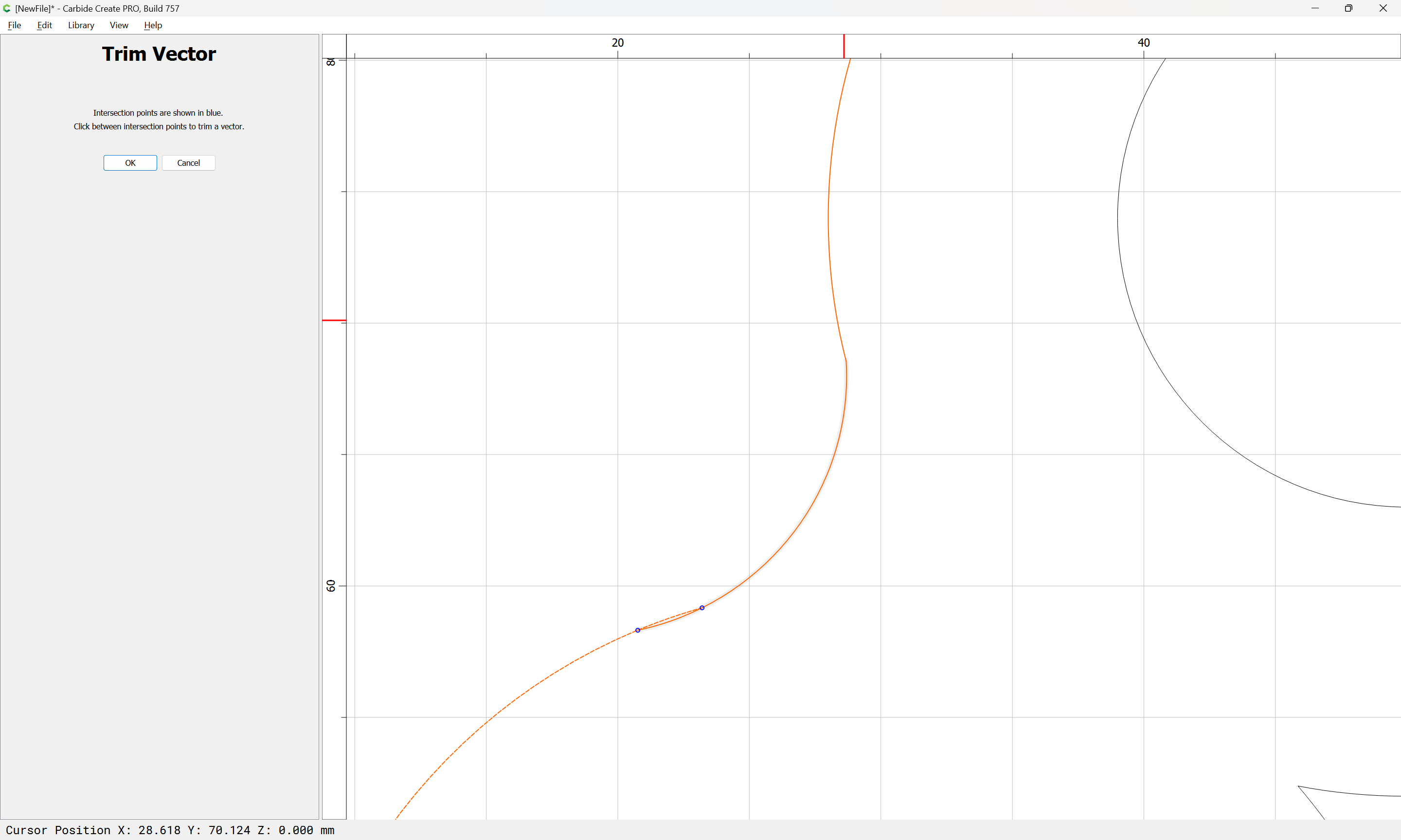
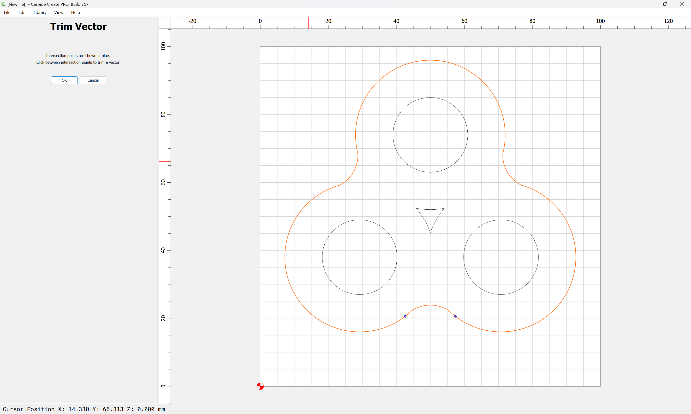
Or the Trim Vectors command:
If using Trim Vectors, click on all the geometry which needs to be removed (the central intersection may be ignored, or left as a potentially decorative element):
until one arrives at:
OK
OK
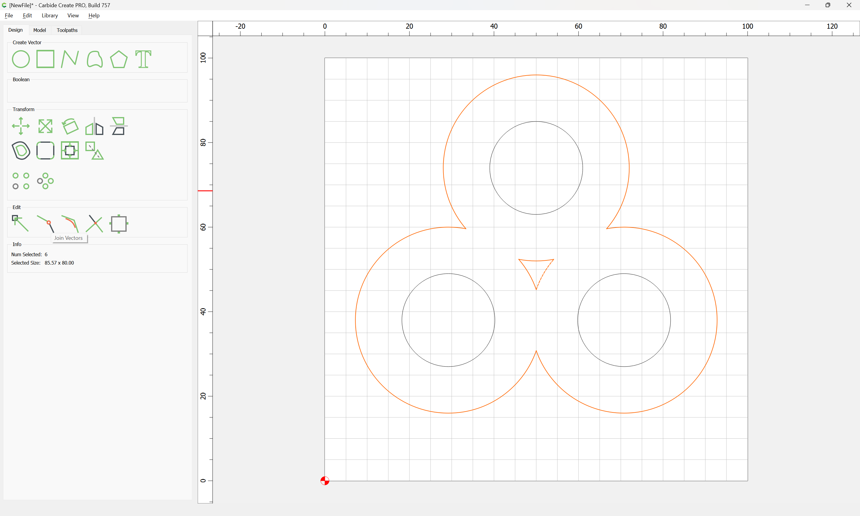
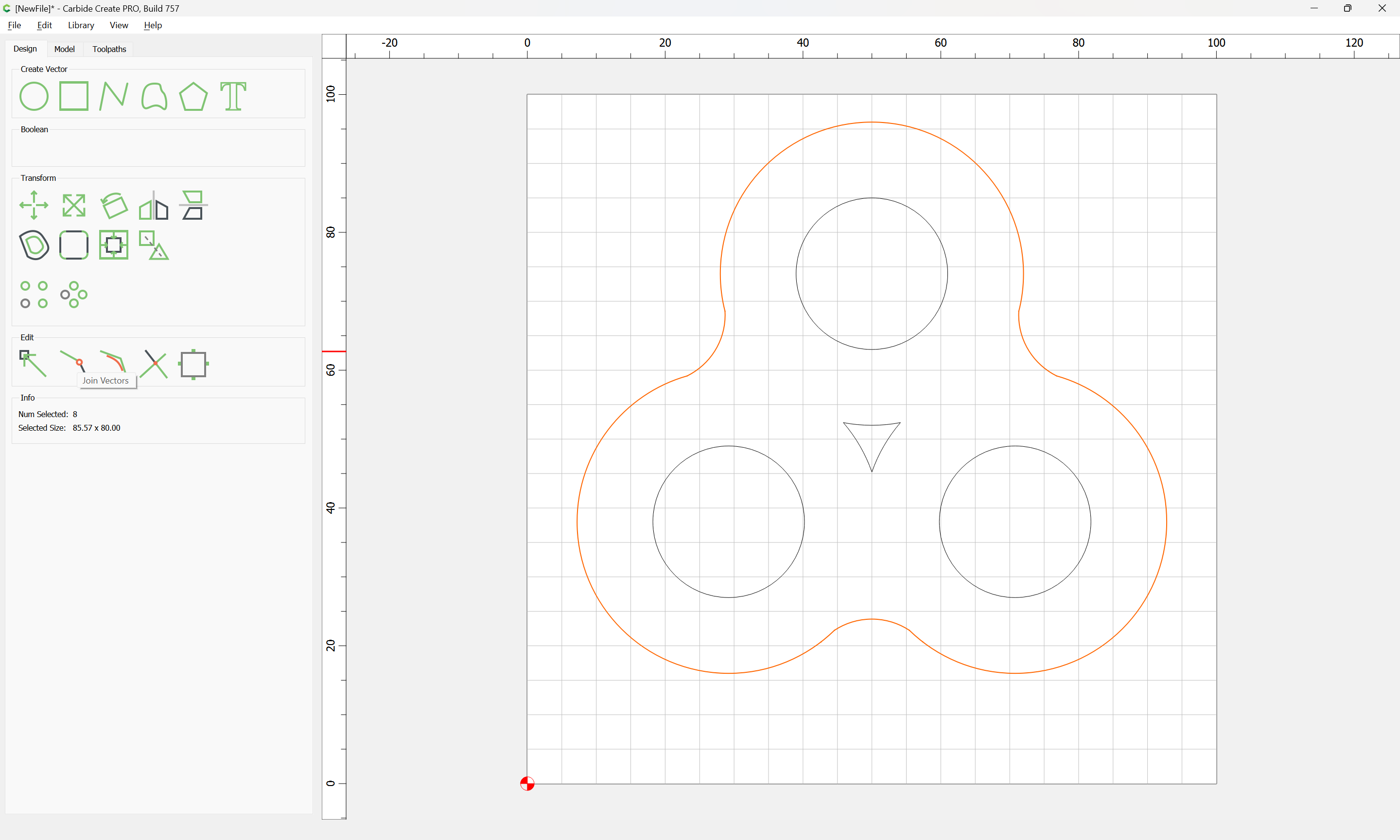
where one may use the Join Vectors command to arrive at:
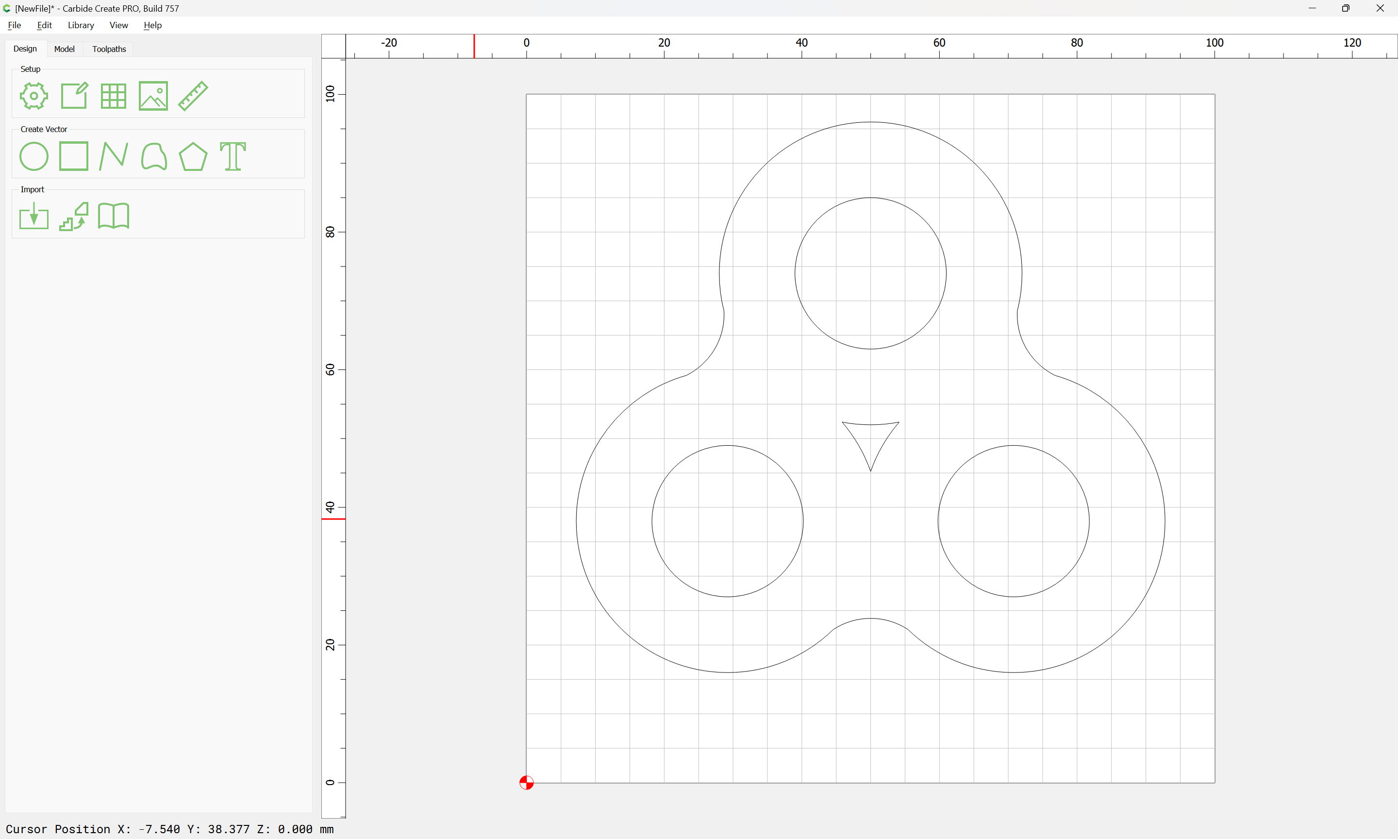
A further refinement is to round the inner sharp corners — unfortunately, the Corner Tool cannot be used here, so it is necessary to draw in and position geometry and use the Trim Vectors command again:
OK
It will be necessary to zoom in to ensure that the inner short segments are removed:
OK
Join Vectors
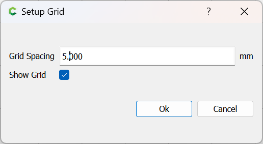
If desired, further smoothing/adjustment may be done.
With the design done, one turns to CAM. First considerations:
To make this simple, we select HDPE, and a 1/4" #201
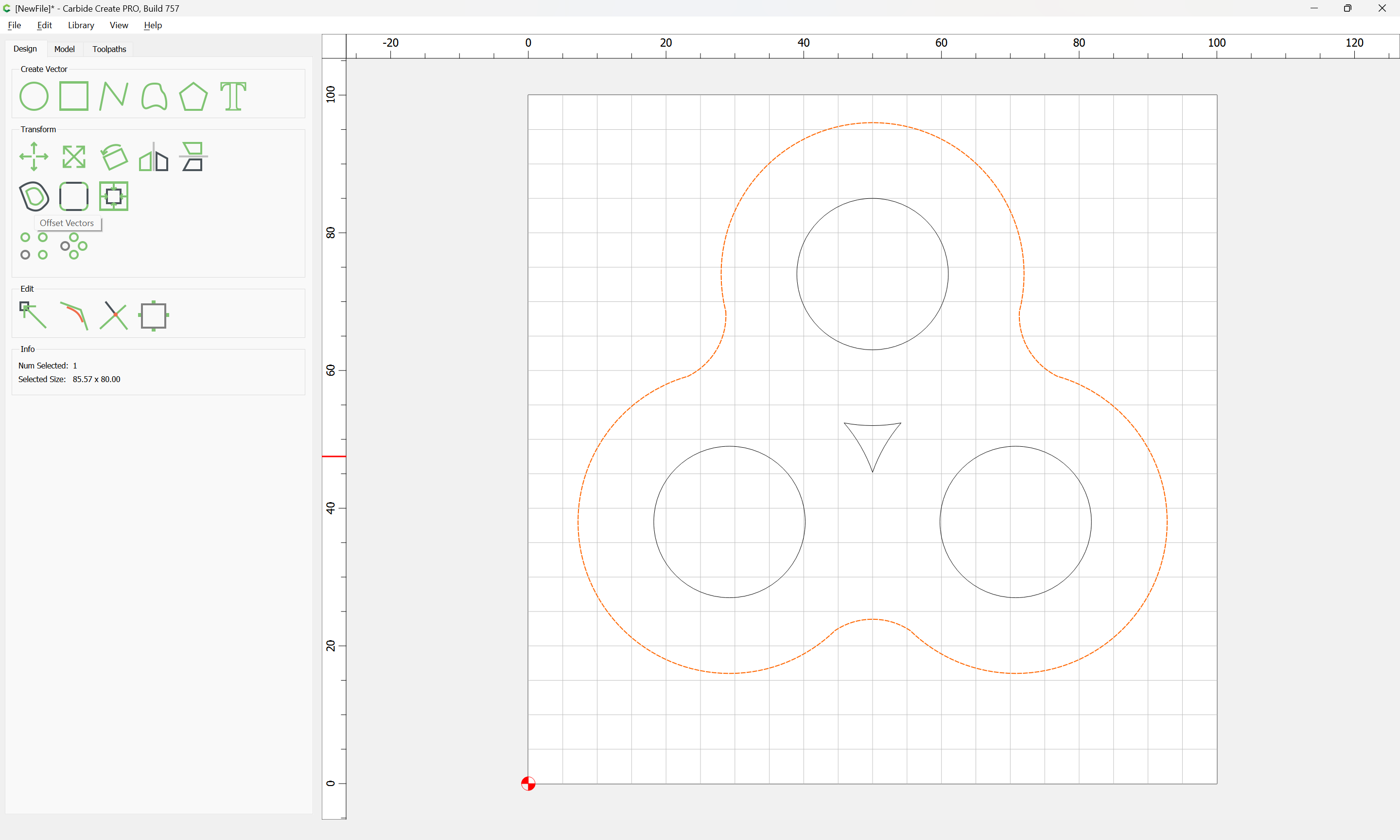
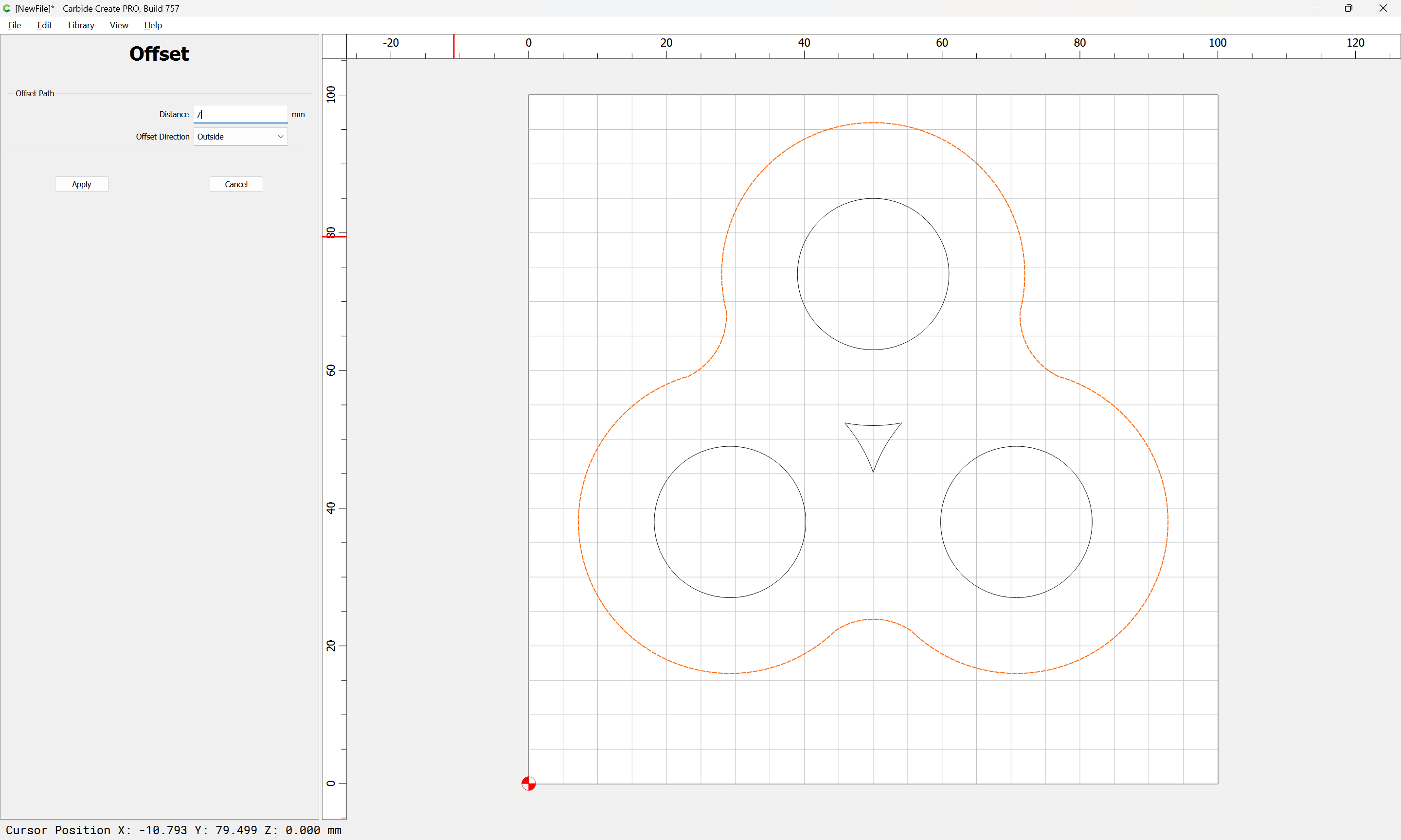
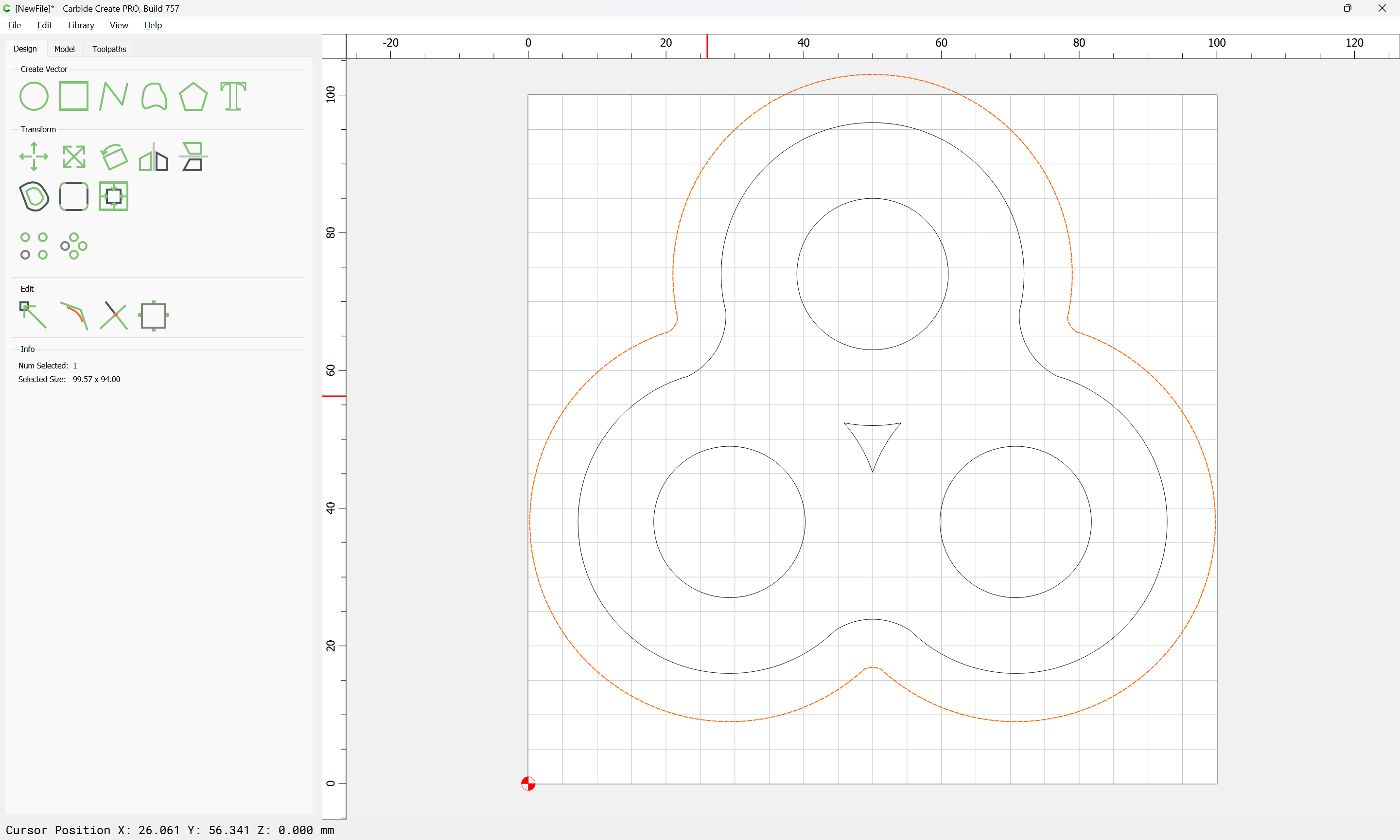
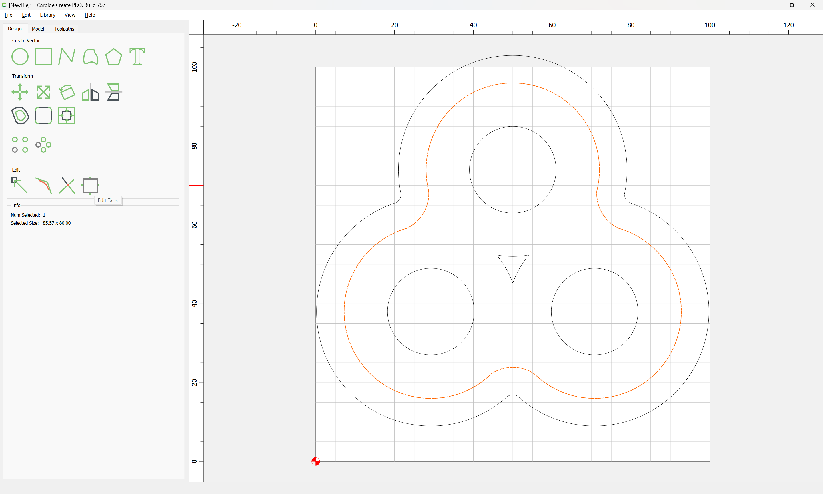
One consideration is that the material may be rather thick, we’ll assume 6.35mm for thickness just a bit less than a 7mm tall bearing, so we offset the outside contour by endmill diameter plus 10% or so:
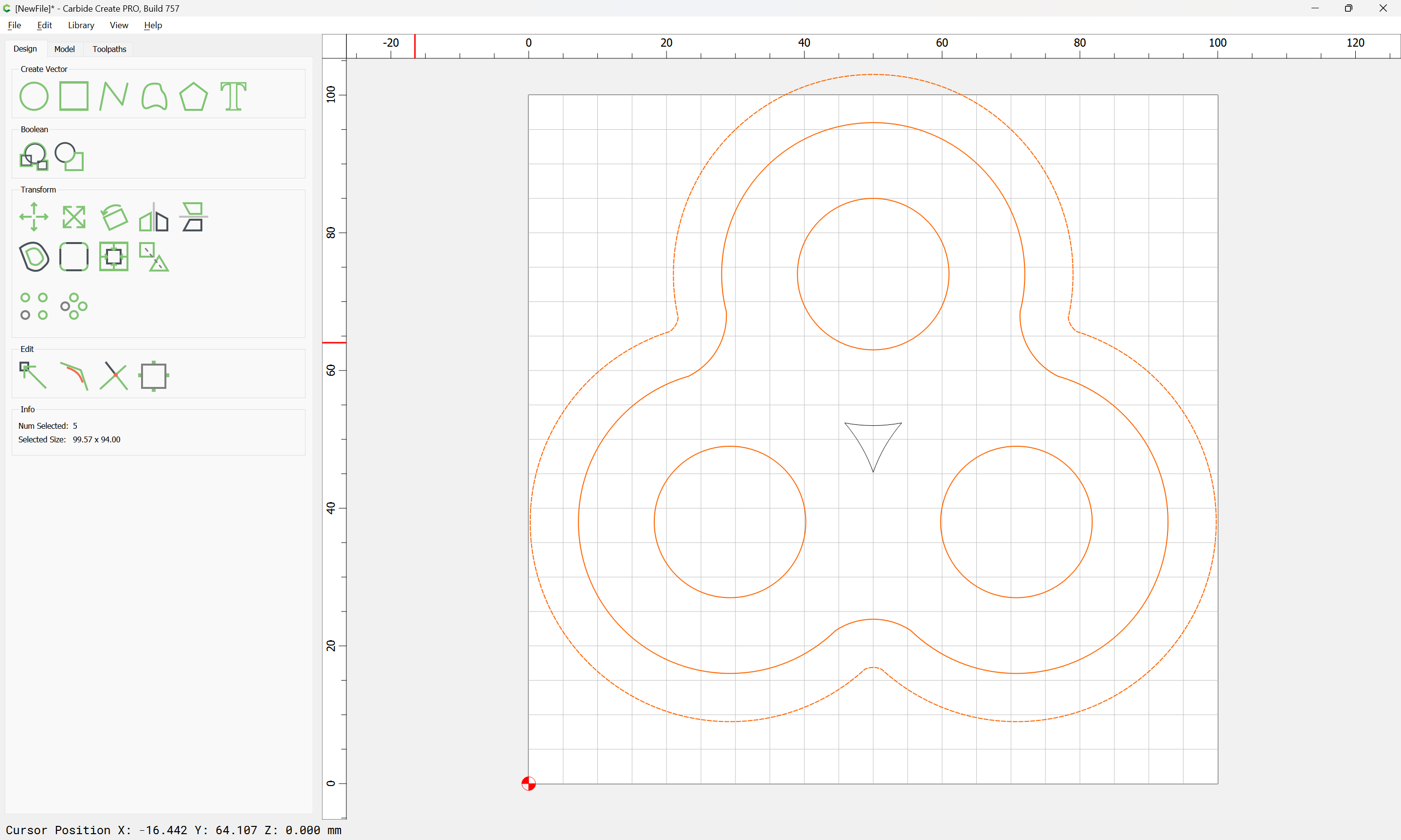
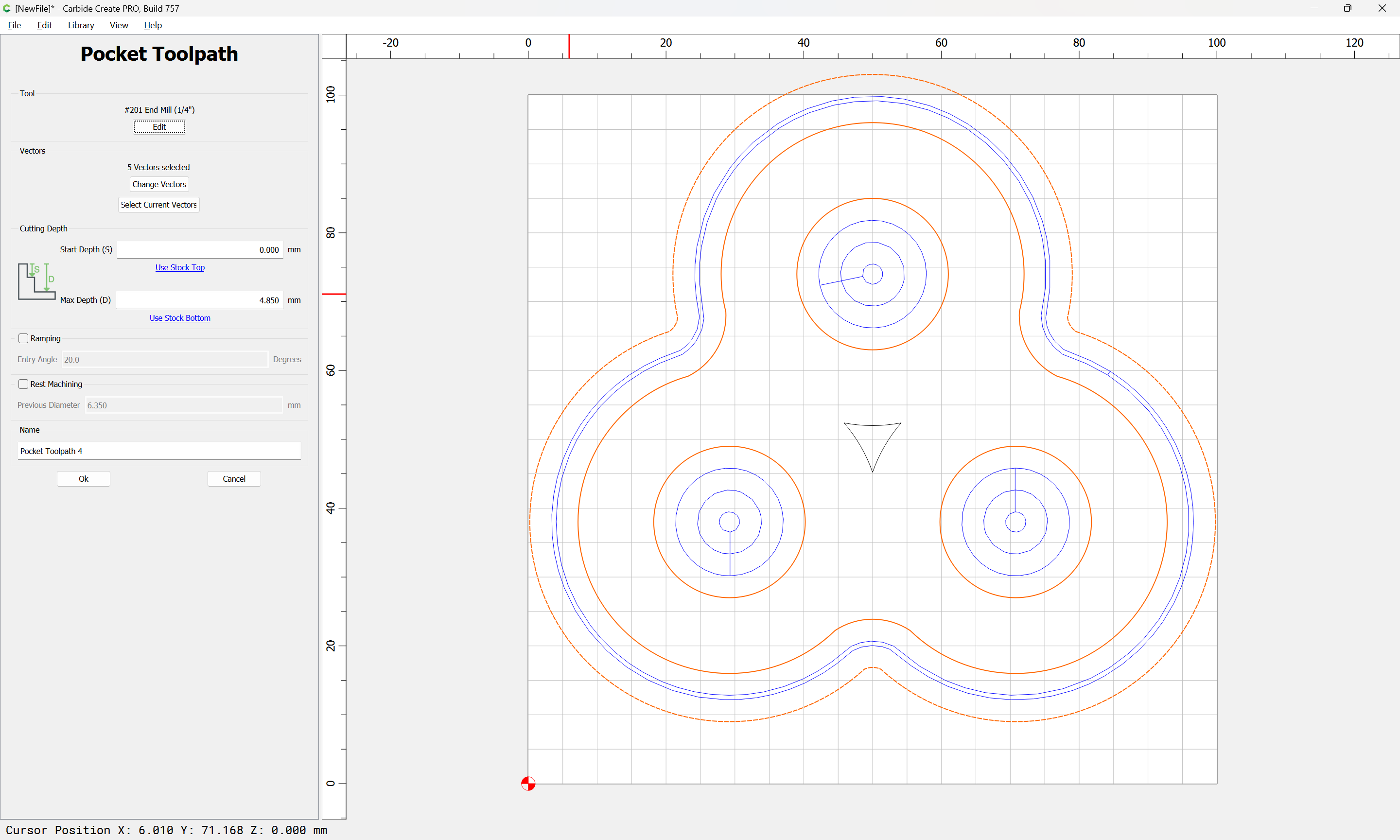
select the inner and outer geometry and circles and cut as a pocket down to tab height:
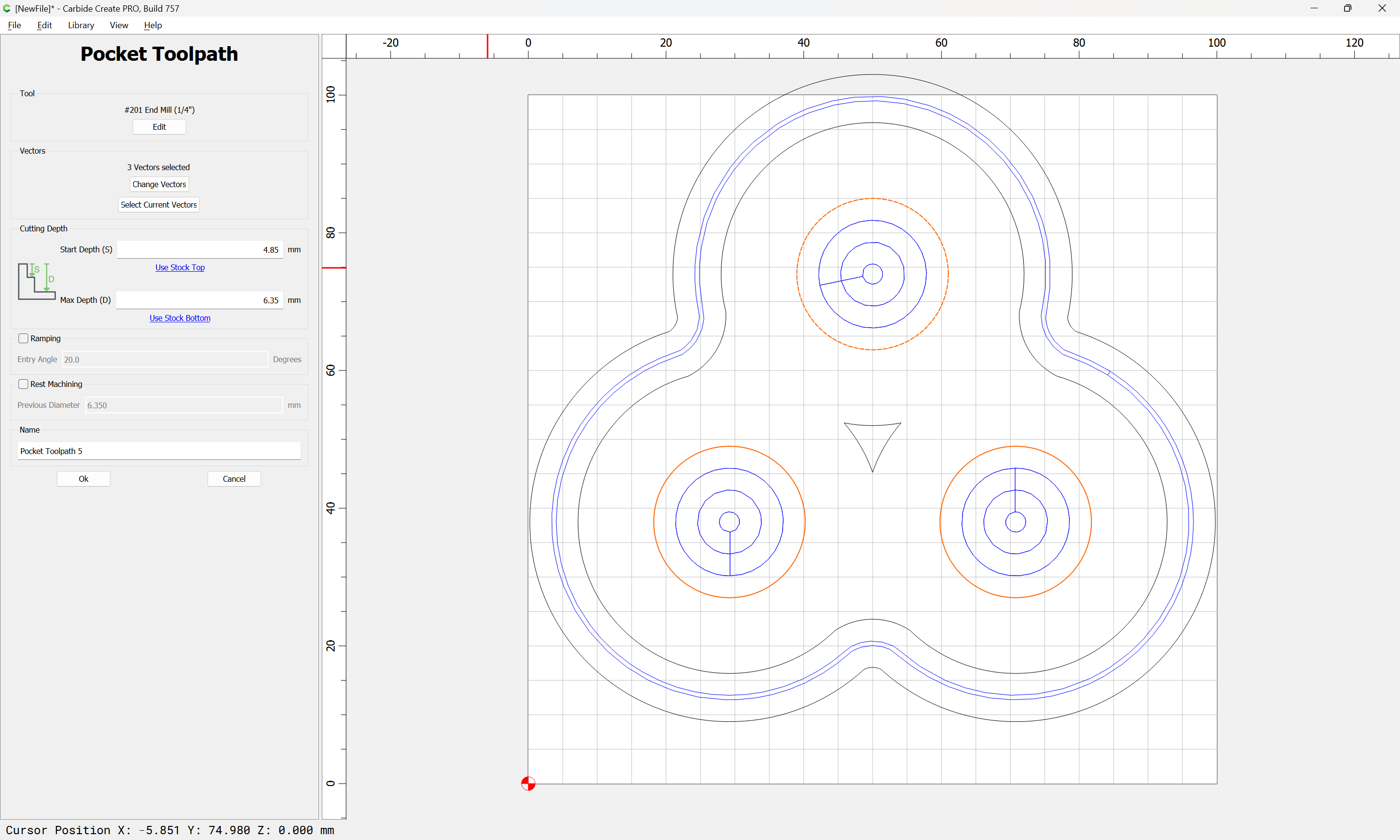
We then finish off the pockets for the circles:
and go back to the Design tab and add them:
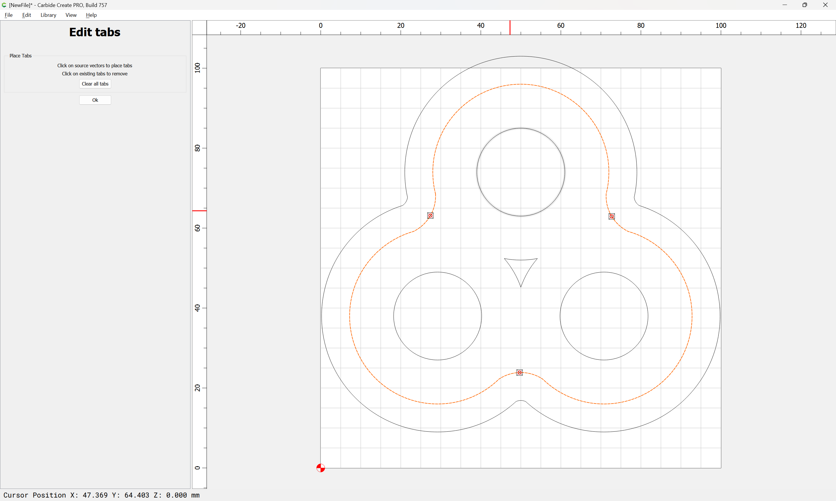
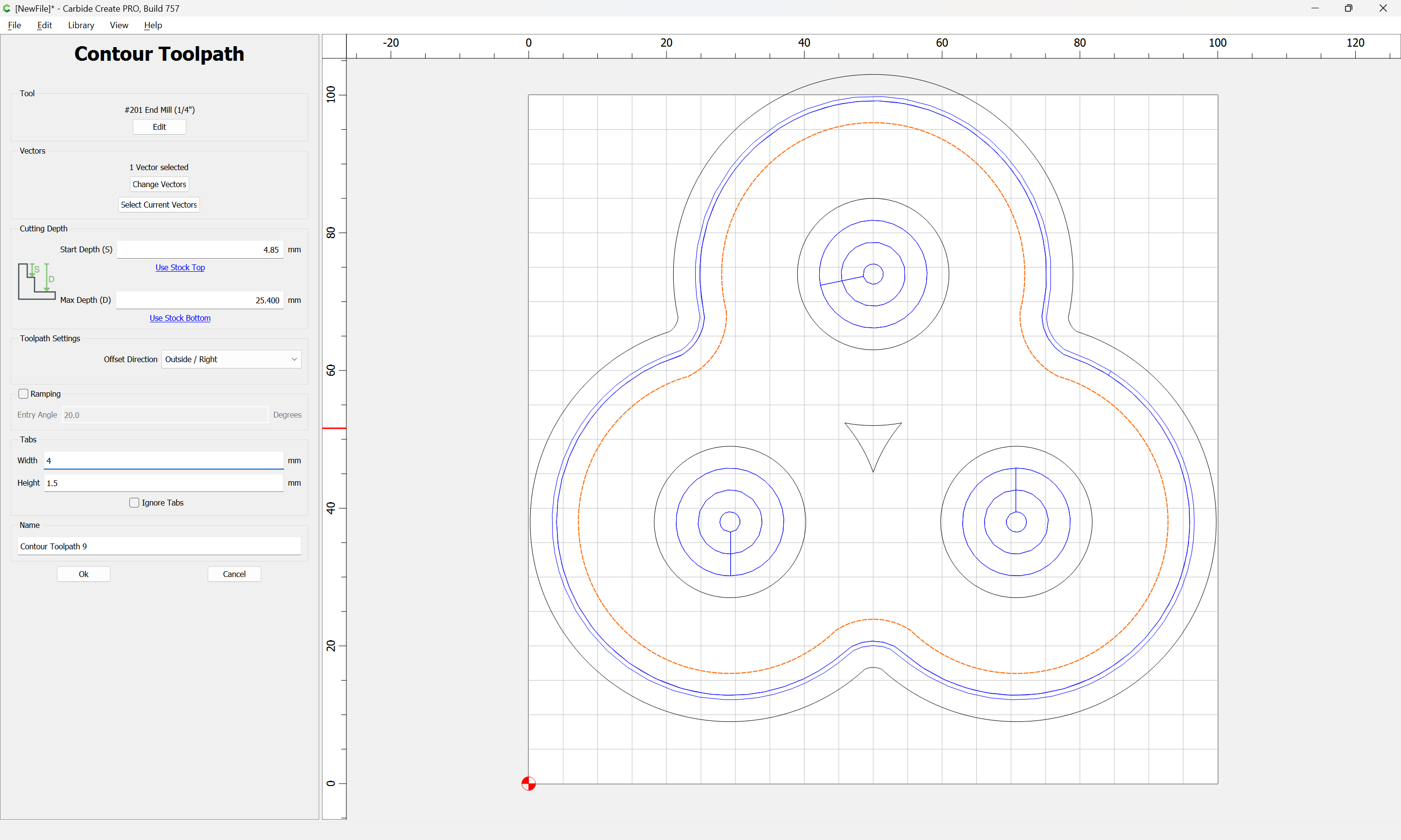
and cut as a contour to finish the cut:
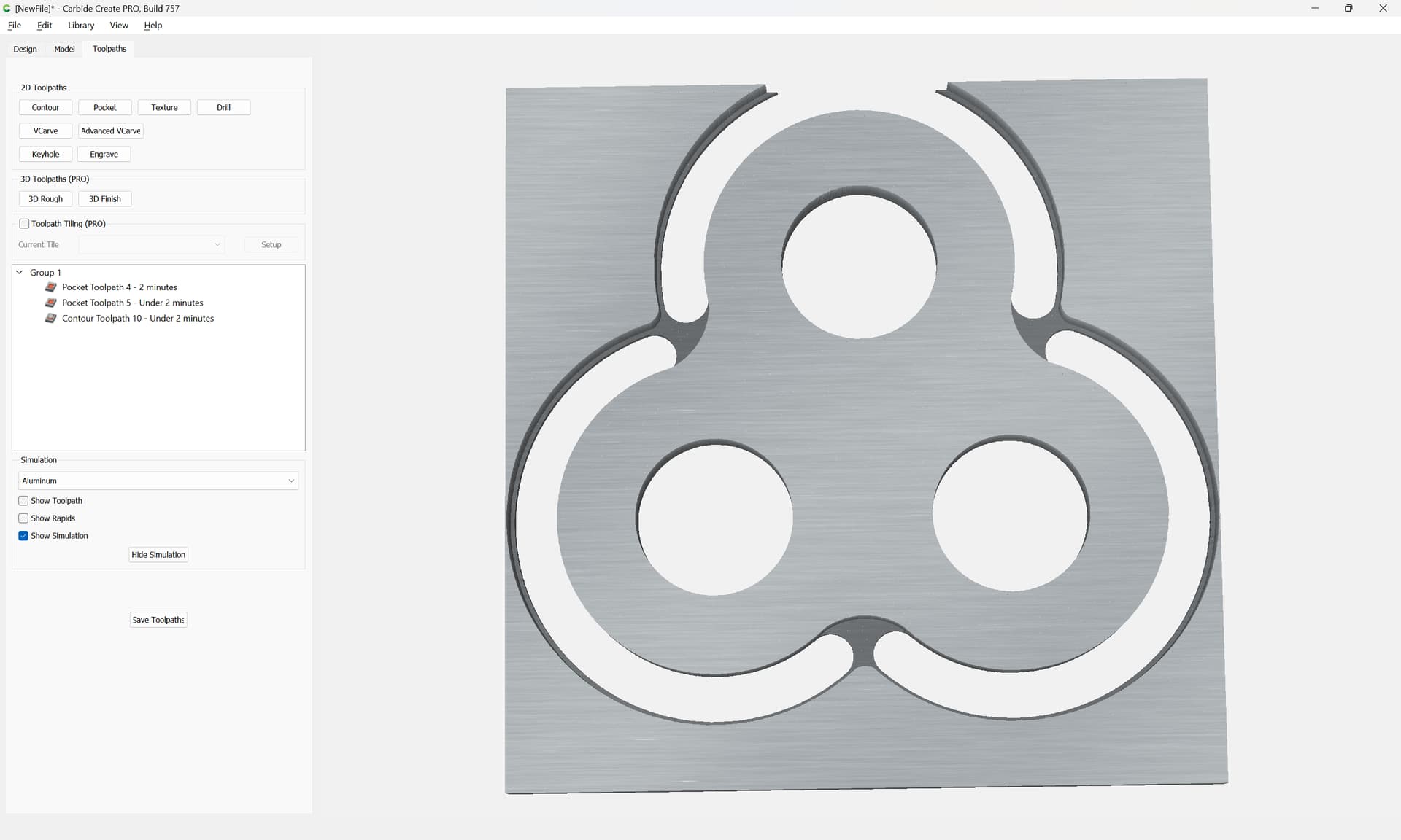
which all previews as:
Be certain to test the feeds and speeds on a scrap piece before cutting.
Clamp the stock in place, home the machine relative to the desired origin, and cut.
How would you have done the spinner using your original drawing instead of the one for which you gave the step-by-step? Would you have used another set of circles to get the concave connections between the three outside circles and then joined them in the same manner?
The original image would have had pretty much the same toolpaths, center, top, right, and left for inner profiles, then an outer profile along the perimeter — should be the same, just skip the drawing/creation steps.
Please let me know if there are any difficulties with the files or instructions — the young man who asked about this on the support e-mails said:
… I made some time and (have) been making fidget spinners like crazy the shapeoko 3 is the best machine ever
(which I was very relieved at — hopefully his parents will grant him permission to share some photos)
Oh. Now I see what you mean. You mean how would I have drawn the original image.
Yes, rotating a couple of properly sized elipses around after drawing them would have worked — I did it in Freehand though, using circles, rectangles, unioning and then the pen tool, since it was faster to draw there than to describe. I’ll try to find time to work up a similar tutorial in Inkscape.
William
I’m not sure a tutorial about how to do it in Inkscape is necessary. I was wondering how you would do it in CC because I think you’d have to add three additional circles to get that concave “web” (it reminds me of the webbing on a duck’s foot). If I were doing the spinner, I’d do it in F360 and use a three-point arc to do the “web” but I don’t remember if there’s an arc tool in CC.
There is a Bezier curve tool, but it’s extremely limited for some reason. I’ll see if I can puzzle out a way to do this in CC. Thanks!
the link https://www.shapeoko.com/wiki/images/4/47/Fidgetspinner.svg is not allow for download - it open a page with the image that is all ??? Thanks
Right click the image and save as
Awesome - Thank You - pls help me
I try to export my file as a DXF file and I got an error, I post on the forums, but no one reply, could you help me? pls see attach of error message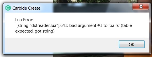
Here’s a zip archive which ought to work:
Fidgetspinner.zip (1.3 KB)
For DXF import issues:
Import DXF
- it may help to use the OVERKILL command to eliminate any overlapping or intersecting paths before exporting from AUTOCAD
- AutoCAD 2000 DXF format (model geometry only, base model scaling) export from the desired face (not isometric view)
2004 Lines
If that doesn’t work, post the file or send it to support@carbide3d.com
