But I thought I would ask here as well in case this is something I just need to learn about the Shapeoko as this is my first test cut.
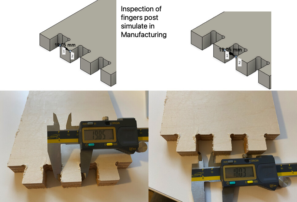
The dimensions of these fingers and slots should be 19.05mm, the fingers are consistently ~1mm larger than they should be and the slots are too narrow.
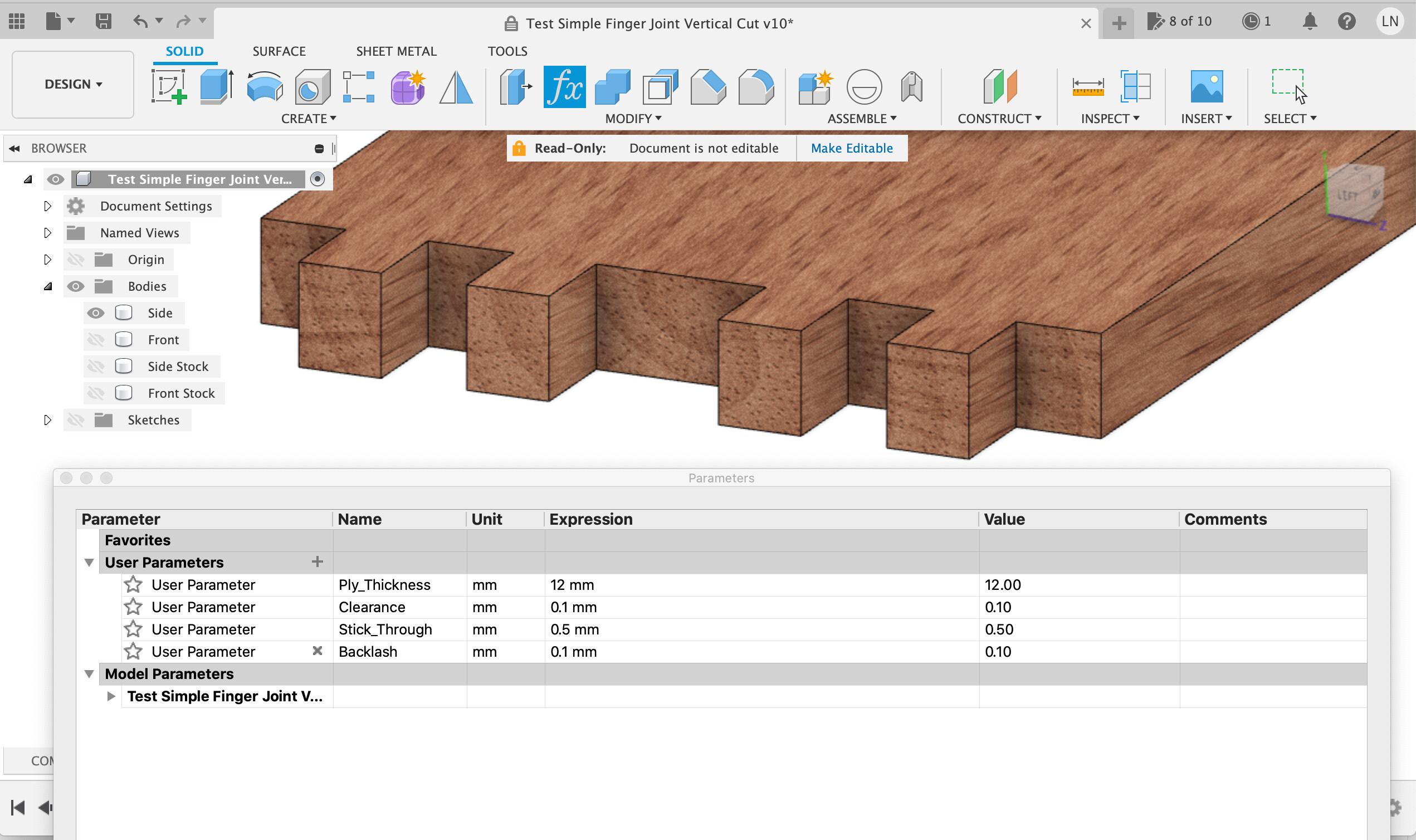
Drawn in Fusion ( 2.0.9854, macOS 10.16.0)
Generated NC with Carbide 3D GRBL post processor ( ver 43182).
CNC: Carbide 3D ShapeOKO and CNCJS Desktop to control it.
Dewalt 611 at #2 (18000rpm)
Bit: Amana Tool 46017-K 1/4 compression bit (new).
Material: 3/4" Baltic Birch plywood
Feed: 1/4" multiple passes
No ramp or lead-ins. My material was not much bigger than the pieces.
The G-code is (unsurprisingly) fine, and should produce 19.05mm wide fingers with a 6.35mm endmill.
X/Y calibration would distort the fingers and slots equally, so that’s not it.
Deflection…could be at play, depending on tool stickout, and since 7mm depth per pass is a lot (on a Shapeoko). A few tests you can try to determine if it actually is deflection:
run the same cut but reverse cut direction in Fusion360 (toggle between conventional and climb, whichever you were using) and see of the dimension changes
run a much lower depth per pass (say 1mm. Yes, it won’t make good use of that compression bit, but for the sake of testing)
Run a clearance pass (with F360 positive stock to leave, e.g. 0.5mm), and then a full depth pass with no stock to leave
That’s not inconsistent with what I found cutting those sorts of joints in plywood.
To get a nice tight joint what I ended up doing was (mostly using parameters in Fusion so I could easily update them and with lots of use of the offset tool on faces)
Use roughing and then finishing passes, do a ‘repeat finishing pass’ to make sure you’re going to final dimension, a roughing pass with cutting load deflects a surprising amount.
Try very hard to machine matching joint halves in the same direction on the machine to avoid differences in X / Y calibration.
Set a ‘stick-through’ for the fingers to come though at least 1mm past the face of the joining piece so you can plane / sand them back flush.
Set a ‘backlash’ value and offset the sides of each finger on each half by this with the offset face tool, start with, say 0.1mm, machine it and measure, this will end up accounting for the cutter diameter error too.
To actually make them fit together the fingers will end up slightly smaller than the gaps, how much smaller depends on the wood and how hard you want to hit it after putting the glue on.
Cutting process
Start off machining with roughing then finishing passes.
Measure what you have with the workpiece still clamped down.
Go back to Fusion, update the ‘backlash’ parameter to a slightly larger number based on your measurement, post-process just your finishing pass and run that again.
Repeat until you get the dimensions you want.
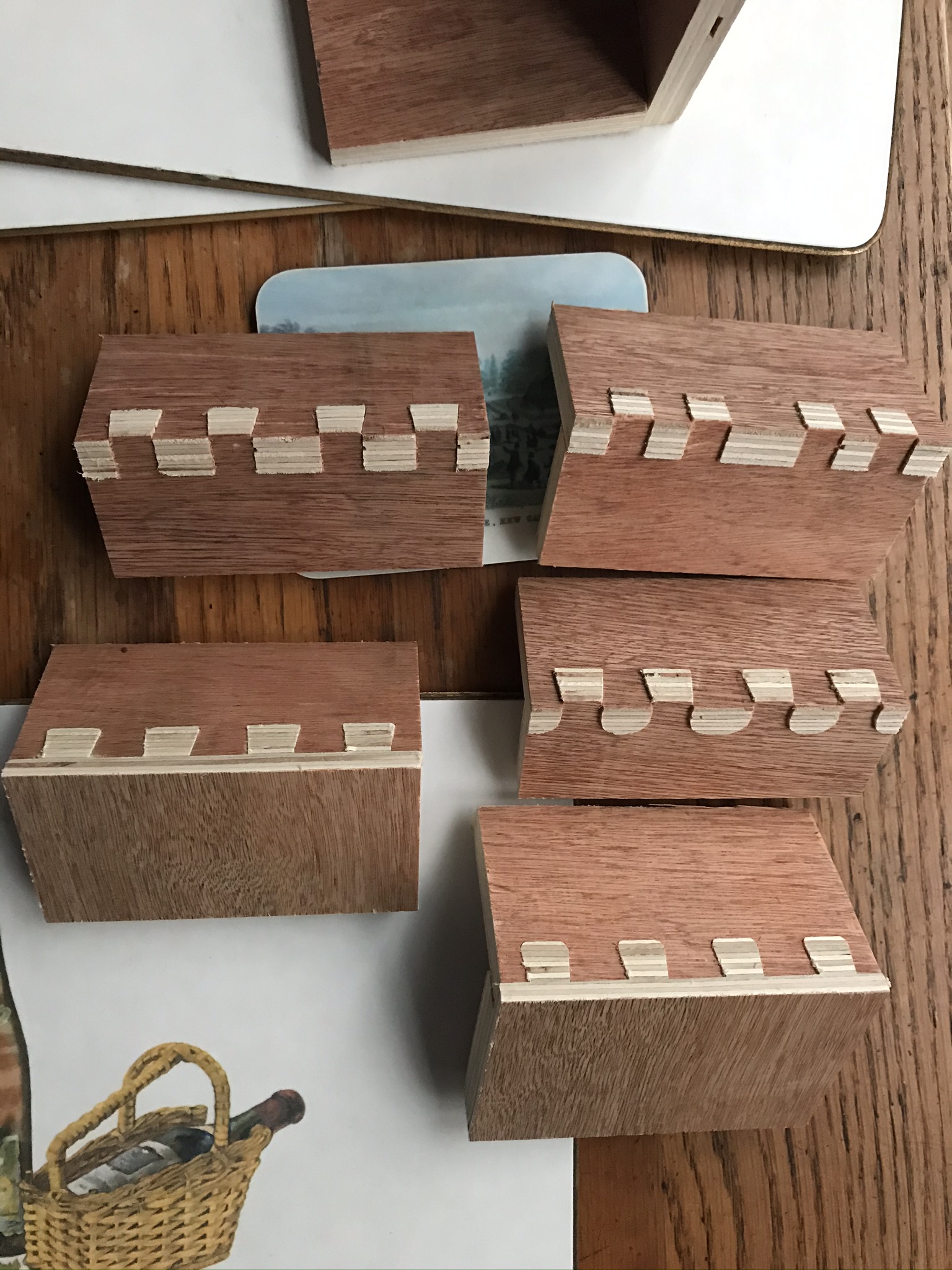
Here’s some cheep nasty ply I used to experiment on various finger / dovetail type cuts on
I guess one of my other issues is that I’m using the Spapeoko 3 at SeattleMakers, so I can’t sit there with my Mac Mini where I do my Fusion 360 work and to re-work live requires more machine time etc… Not ideal, but it is what I got.
When I do dial this in, I’ll also update my personal Maker Notes which I keep on how to use the various machines.
But between you and Julien, I have some really good things to try. Thanks again!
I also generally put “material thickness” in my params so that I can measure it for each new sheet of stock and set it accurately, they’re never quite on spec.
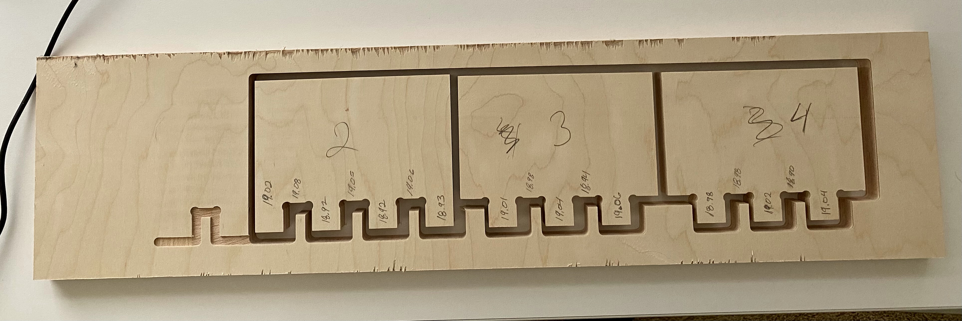
OK here are my results. I was going to test some different things, but I wasn’t prompted to change the tool hence the abandon cut.
#2 - 2mm depth of cut, Dewalt Speed #2, Amana Tool 1/4 downcut bit #3 - .25" depth of cut, Dewalt Speed #2, Amana Tool 1/4 downcut bit #4 - 2mm depth of cut, Dewalt Speed #2, Amana Tool 1/4 downcut bit
Surface feed rate was 353.429 m/min and a feed per tooth of 0.0423333 mm, both of which comes from the Amana Tool library. I did measure the bits to be 6.25mm and adjusted that in the tool configuration.
In my first attempt, the surface speed for the compression bit was 357.954 m/min and feed per tooth of 0.079963 mm. I find that interesting that this is different. I don’t understand the feed per tooth well enough to set if it was meaningful.
No tolerances, backlash adjustment, glue or assembly allowances etc. are in the designs. They should all be 19.05mm. This is a test, no pieces I plan on using.
My work piece was ~4" from the front rail of the Shapeoko more or less in the center.
#4 was was supposed to be cut down to .25 at 2mm and then tool change to the compression bit. But no tool change was prompted so really #2 and #4 are the same parameters.
Results
The downcut only bit at 2mm or .25 in. produced good results.
My guess is for a shared machine with others users and a machine that is not immaculate (dust on the tracks, wheels, etc…) that .13mm variation is pretty good.
As-is these pieces did fit together, super snug which was to be expected with no added tolerance or allowance for glue.
The downcut bit cut clean both on the top and the bottom side. The workpiece was sitting on a fresh piece of 1/4" MDF wasteboard and was fully supported. So probably expected.
My takeaway is use the downcut bit at 2mm cuts.
I do wonder if there is some lack of accuracy on this machine closer to max X,Y. It would be interesting to put a full pieces of test MDF on the device and cut in a pattern across the surface to test that theory.