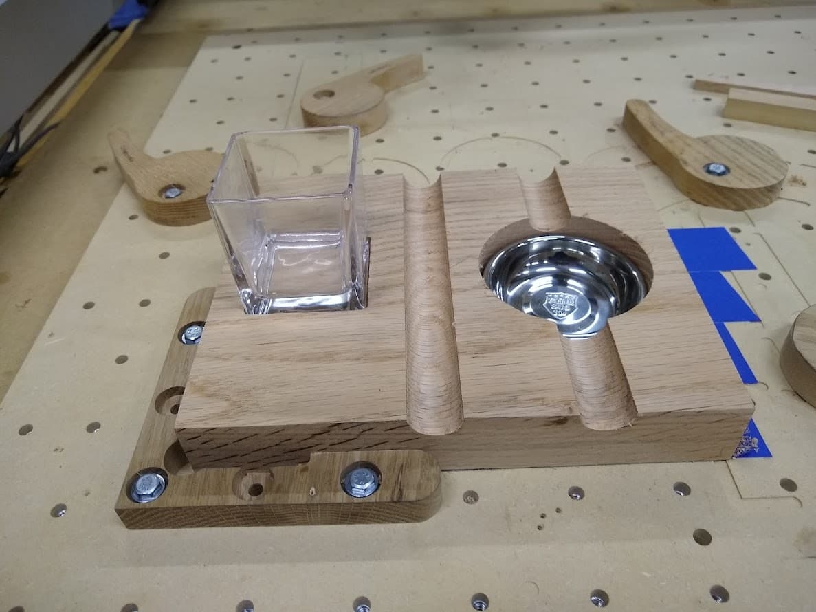
I am making a Whiskey Glass and Cigar Holder and Ashtray. I found the idea on youtube and I have made the project. I cut it out on a piece of cracked oak just to see if it would work. The carve came out pretty good but my 3d element are the half pipes that are cut to hold a new cigar and over the ashtray the same object to rest a burning cigar.
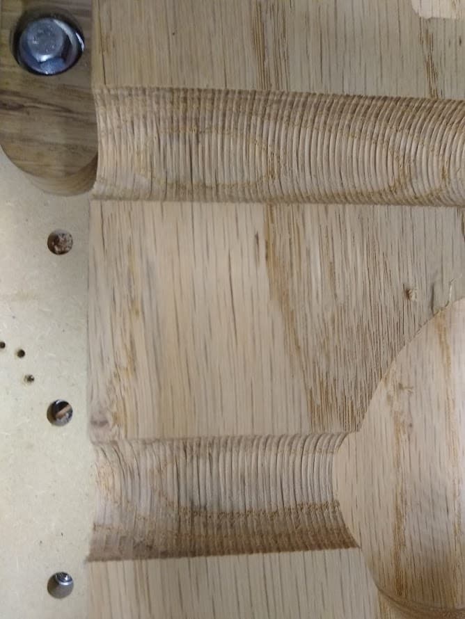
The issue is the half pipe is rather rough. I made a 3d roughing pass with the #101 ball nose bit and then a 3d finishing pass. However it looks rather rough.
The pictures are as it was cut while still sitting on the machine.
Can anyone make a suggestion to make the half pipe objects smoother.
Another thing which might help is to change the angle by 90 degrees, so the movement is in-line w/ the channel, rather than going back-and-forth across it.
@WillAdams I had asked for some help with the modeling about a week ago. You had suggested I use 89 degrees in the model. Now that I have actually cut a 3d model I was wondering why you suggested the 89 degrees. I will try your suggestion to cut across the grain. This type of machining is new to me. @robgrz suggested a bigger cutter. I dont think I have but the #101 1/8" ball nose but I will see if I can get a larger ball nose bit and try that along with Will’s suggestion to turn the cutting 90 degrees.
The 89° was to build the 3D component for the round slot. (90° will also work)
The 90° suggested now is the direction of the cut. Cutting across the slot at 0° you see the scallops from the stepover. Cutting with the slot at 90° the scallops will not be as pronounced. (round cutter on round cross section = better finish)
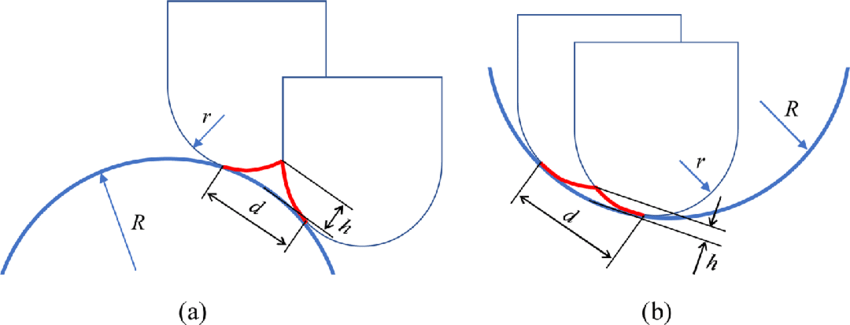
comparison on convex vs concave with same tool & stepover