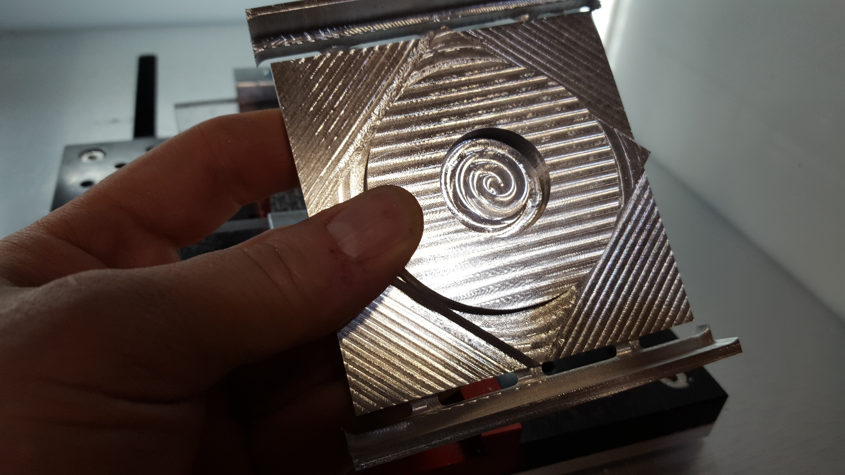
I finally got my first Nomad part done. I fully admit that it took me to task relearning the proper strategies. This is a circle/diamond/square test which is very common in machining circles to test a machine. Even with me re-machining this piece 7 times in some areas (while I was teaching myself over and over again) The worst deviation from nominal was 0.007". I think my wall finishing strategy is to blame for half of that. My tool diameter was also around 0.002" smaller than nominal which I did not account for in my programming…so there is also half the deviation. This is evident in my measurements since they are larger than nominal, which is how a smaller diameter tool manifests itself. In depths the highest deviation from nominal was 0.002". I think that is more representative as finishing strategy is not nearly as much of a factor. So even with a rusty programmer, it is very capable of holding tight tolerances. Now to make some more of them and refine my programming to get better finishes. I’m also waiting for a 1/4" collet to arrive so I can face the top surfaces with a larger tool.
This is great, maybe if you could provide a bit more info so we can all learn. What material, F&S, endmill used, etc. Did you use Meshcam or F360?
This is 6061.
I used the standard #102 endmill that comes with the Nomad.
I used Fusion 360. I’m going to refine the files more from the experience I gained. Once I do, I will share my file. Most of the work was done with adaptive. 10k RPM, 40 IPM, 0.030" optimal load, 0.040" stepover, leaving 0.020" axial and radial. I think next time I will reduce the stock to leave to 0.005"-0.010" as the Nomad is more precise than my XXL and I can leave less margin for Z axis deflection. Finishing was done at 10k RPM, 40 IPM.
I was mostly pushing feeds as much as possible, which is great for the adaptive operation, but I know there is a lot of room for improvements as far as finish goes in the pocketing and contour operations. Especially at the top and bottom of the Y axis where the vise jaws/tabs were.
interesting, chipload of 0.0017" (after chip thinning), that’s slightly above what I would go for in 6061 with a 1/8" endmill.
What DOC /maximum roughing stepdown?
I am learning that I’m having to reduce chip load. I reduced it to 0.0015" with success. I tried it with 2 way adaptive and found that on the second direction it will stall. So I’m playing around with the recipe more to either stick with single direction, or reduce optimal load. This is all adaptive roughing. All finishing passes are now being kept to a 0.001" chip load.
If I remember correctly, there is an option in F360 to use a different feedrate (hence chipload) for each direction when using both-ways adaptive, so if you really want to use both-ways, you may benefit from reducing the feedrate slightly in the second direction, so that you do not have to degrade the overall feeds & feeds just because of that second direction.
You’re correct. That’s what I was thinking in my head, but didn’t get put down on the post.  You can reduce optimal load and feed rate for the second direction independently. Messaging with Vince, looks like around a 25% reduction is needed. I was going to try the reduction in the stepover first and try to keep the feedrate the same. My hope is that reduced the load enough without reducing the feedrate to a point where chip load is too low and the aluminum sticks to the flutes.
This topic was automatically closed 30 days after the last reply. New replies are no longer allowed.