First piece of furniture made using my CNC router

I acquired my SOP just over a year ago. The first year, being a new CNC user, I familiarized myself with the machine by doing small projects such as various boxes/cases, Astek calendar style of StarWar and others. In the fall I designed and made my base for my CNC. My new Shapeoko base cabinet with vertical mounting - #15 by Bobster

On the software side, several years ago I occasionally used Sketchup for carpentry projects and then for 3d printers. Then I switched to the software Fusion 360, free version for hobbyists for my 3dprinting. For the CNC I did my first projects with Carbide Create then depending of the kind of projects I used also Fusion360.

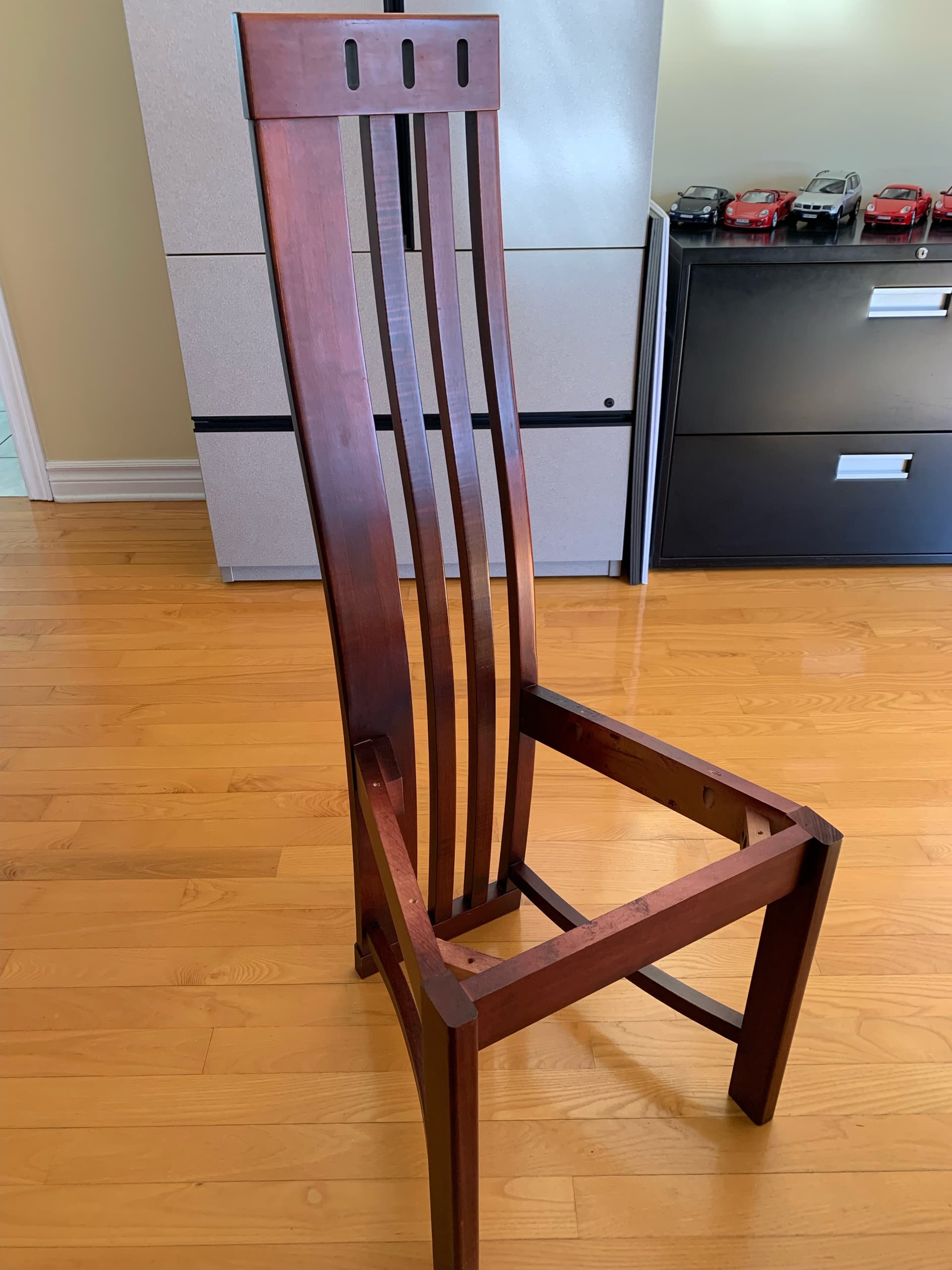
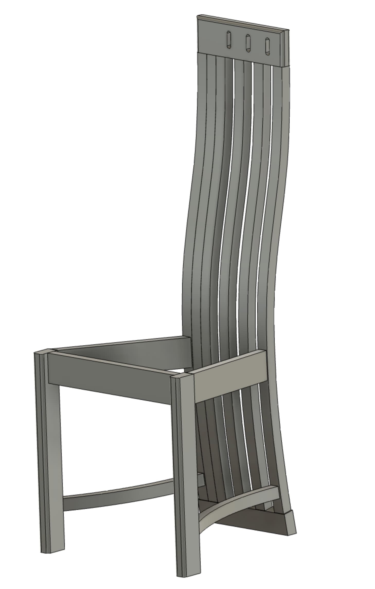
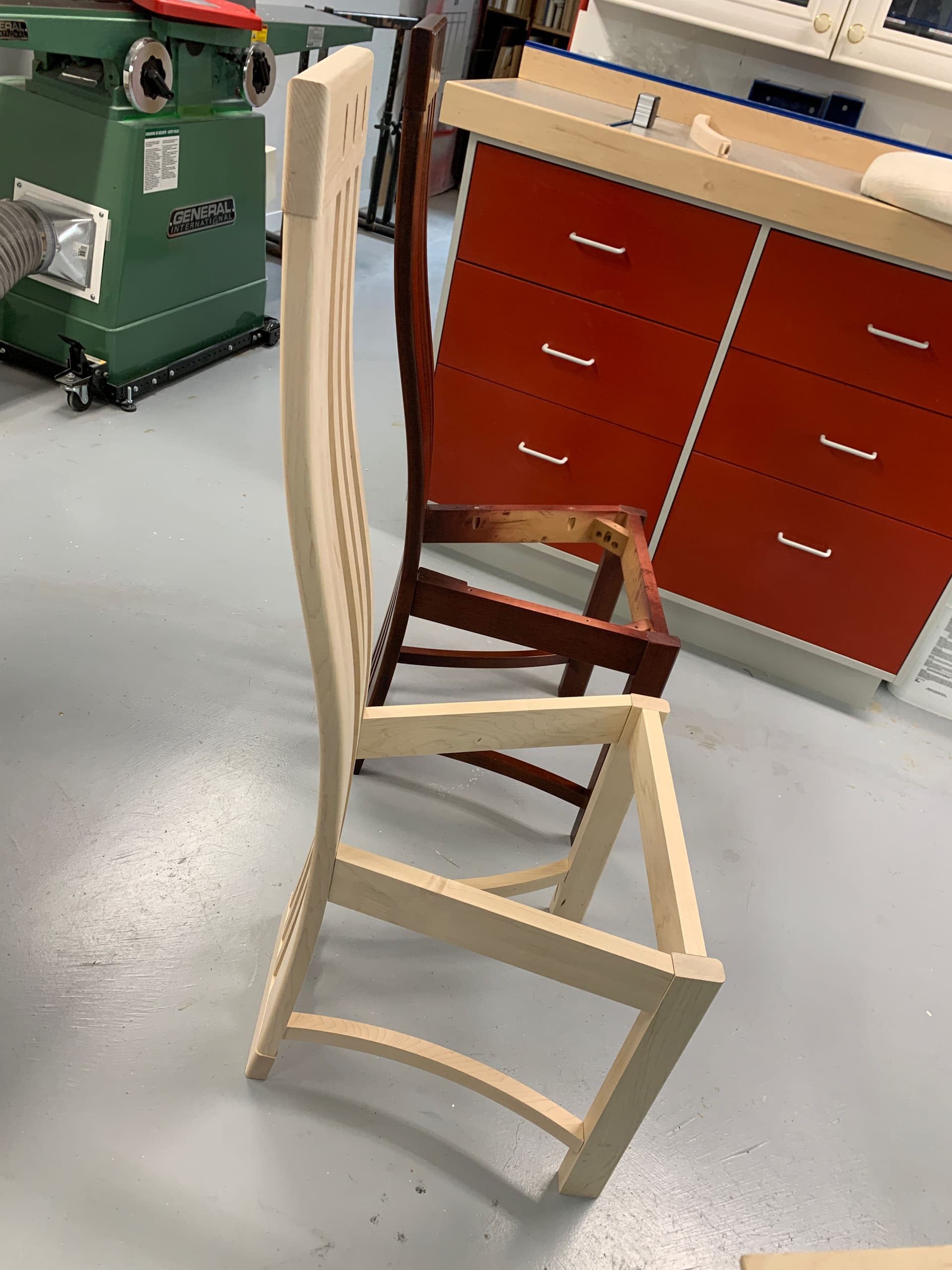
After about ten month, having added a water cool spindle and required installation, I decided to undertake a more complex project (at least for me), I wanted to add 2 chairs to my dining room set which is decades old (25~30 years old). Here is a photo of the model. Note that the side rails and bottom rungs are at compound angles.

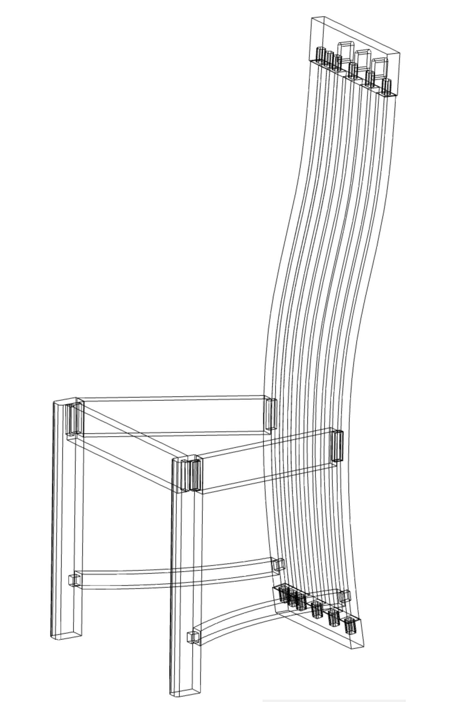
My first challenge was to design the chair with Fusion360, I was not very familiar with the software, only used it for small projects for the 3d printer and some of my small CNC projects. The learning curve was a little, a lot difficult with many religious words! But I got there and I learned a lot. At almost 70, memory doesn’t work as well! Here are the pictures of the drawings of the chair.


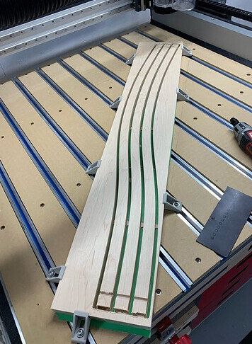
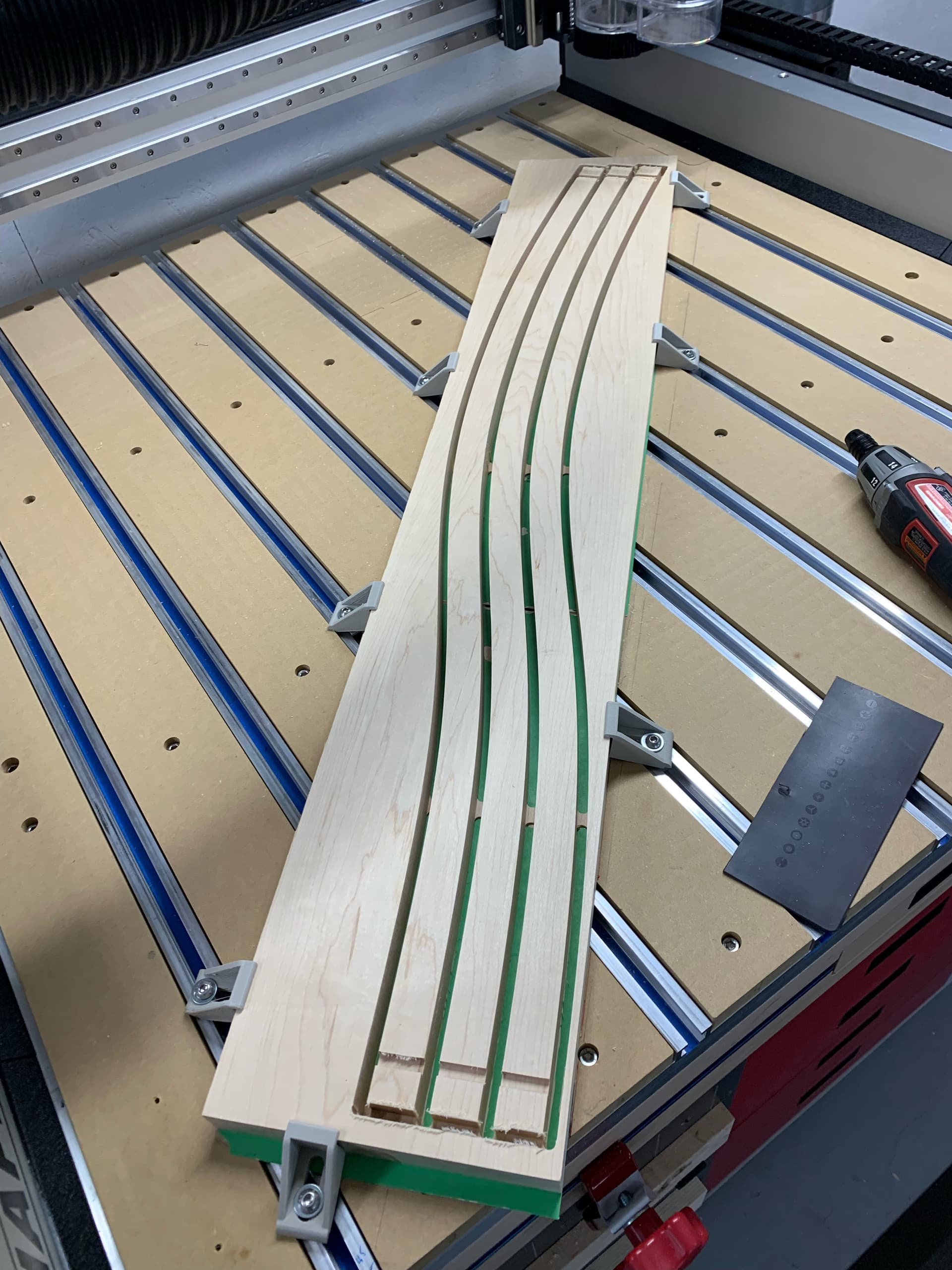
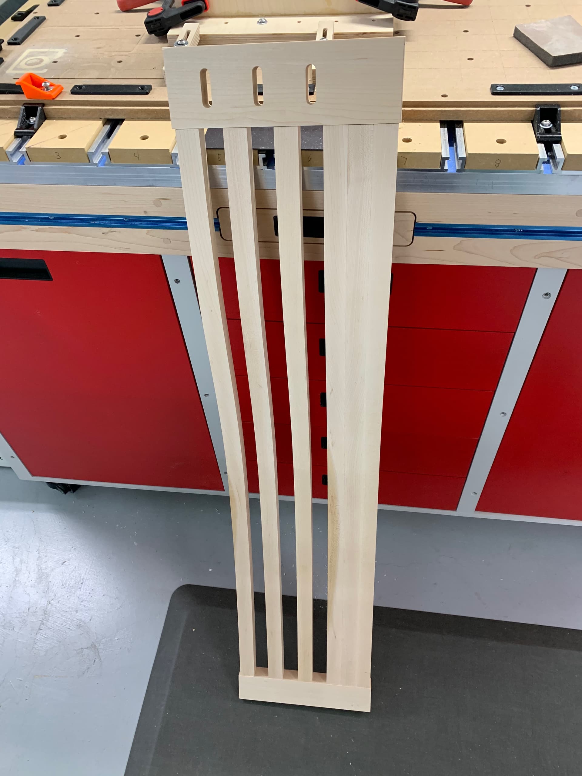
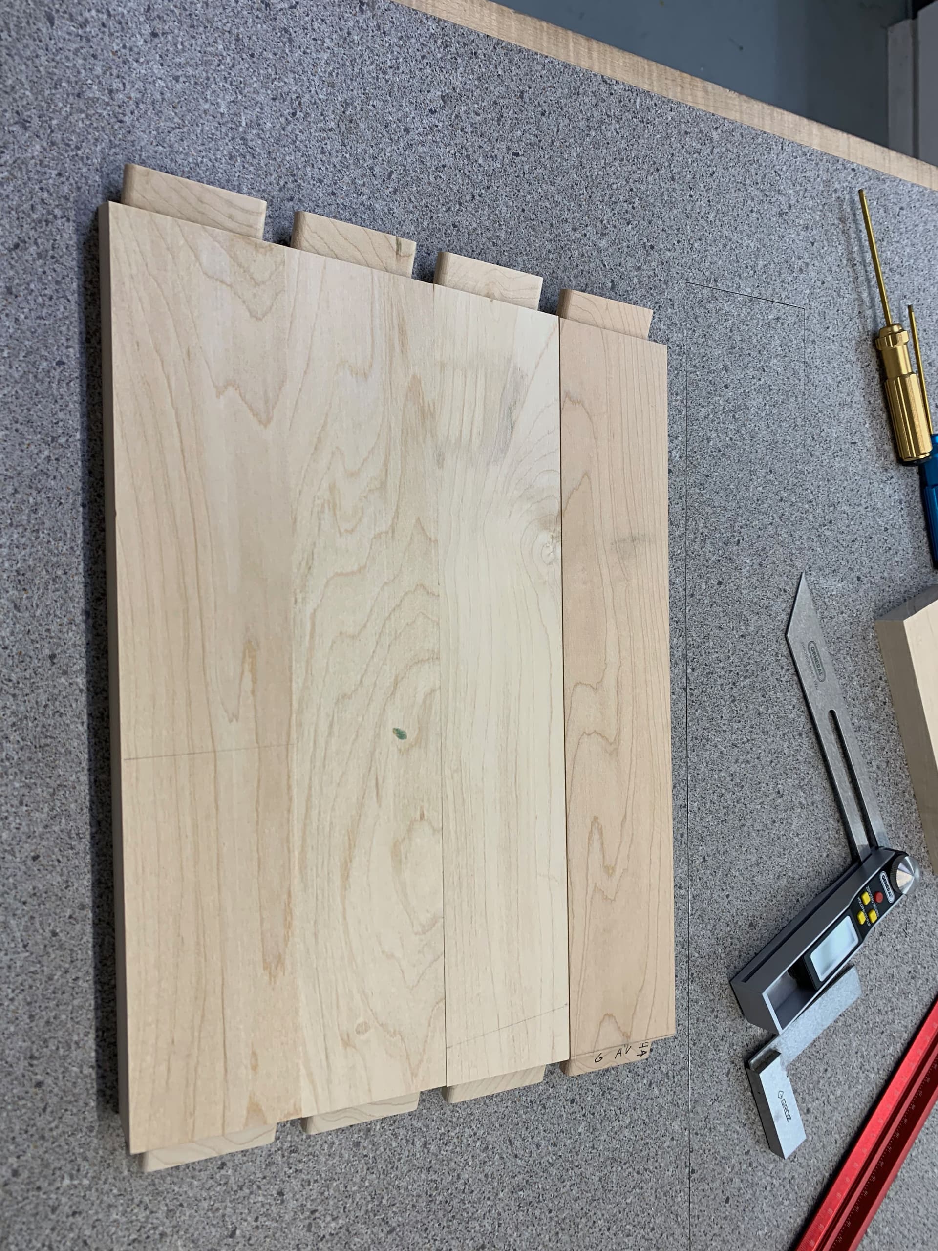
I started by making the vertical parts of the backrest. I need 6 identical pieces per chair, for a total of 12. Wisdom comes with age, I made 14 which was a good thing. Two 4-pieces boards and two three-piece boards. Since the SOP has around 34" by 34" working area, I had to cut my parts diagonally across the table. Here is a board with three cut pieces. The demarcations at each end mark the beginning where the tenons will be.

By removing the pieces from one of the boards which contained 4 of them, one of the pieces came out crooked and twisted! There was a lot of tension in the wood…

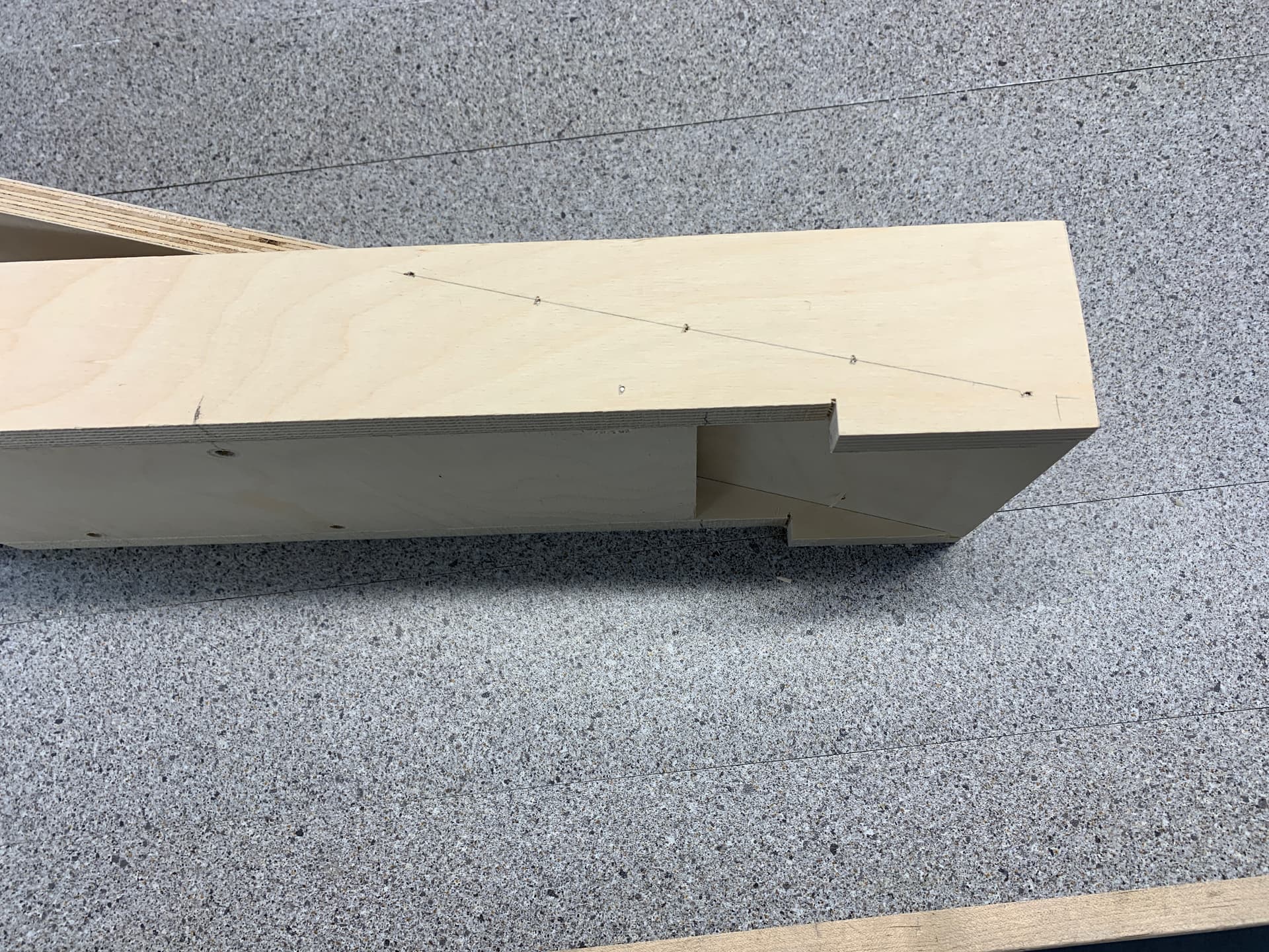
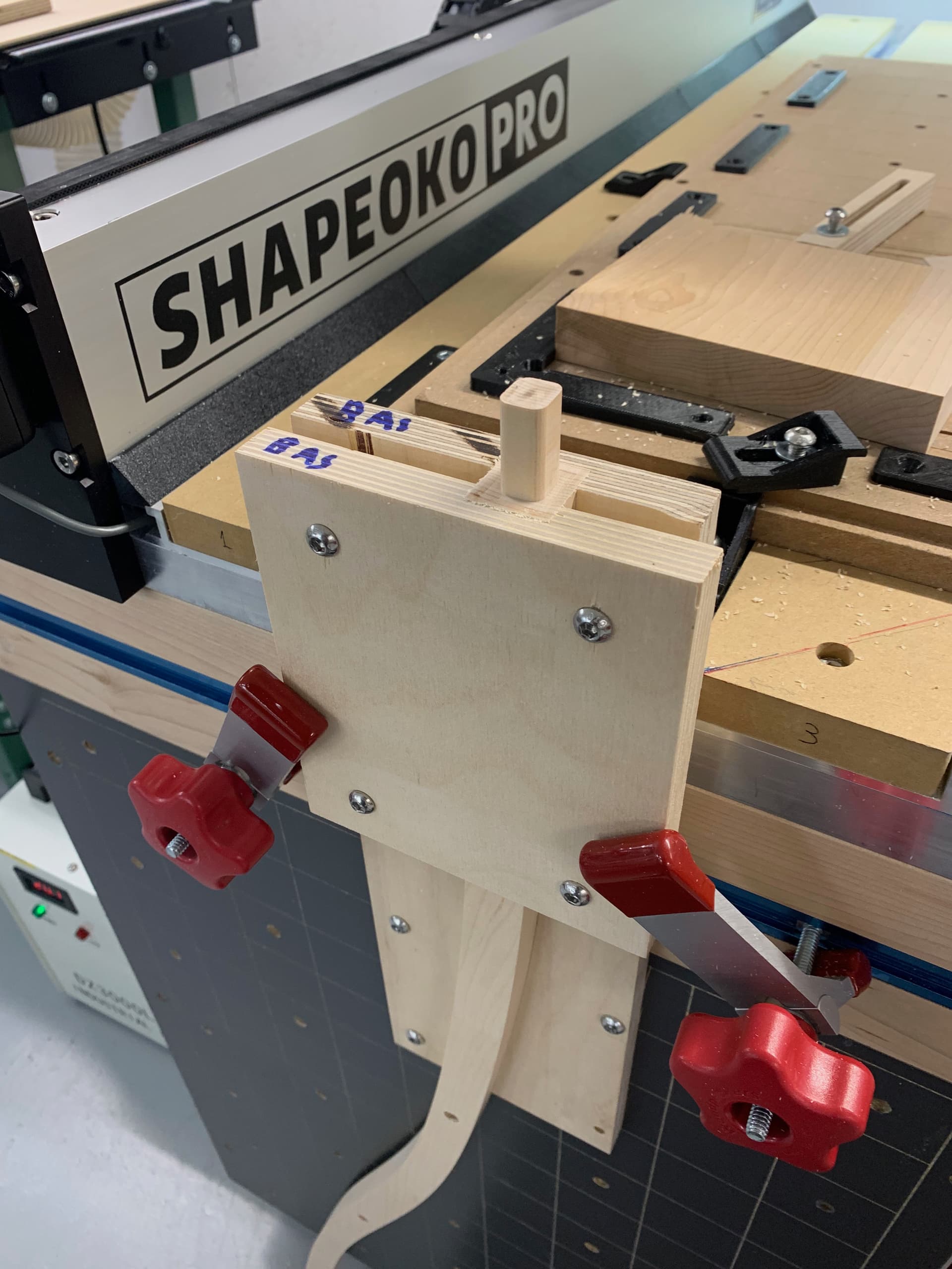
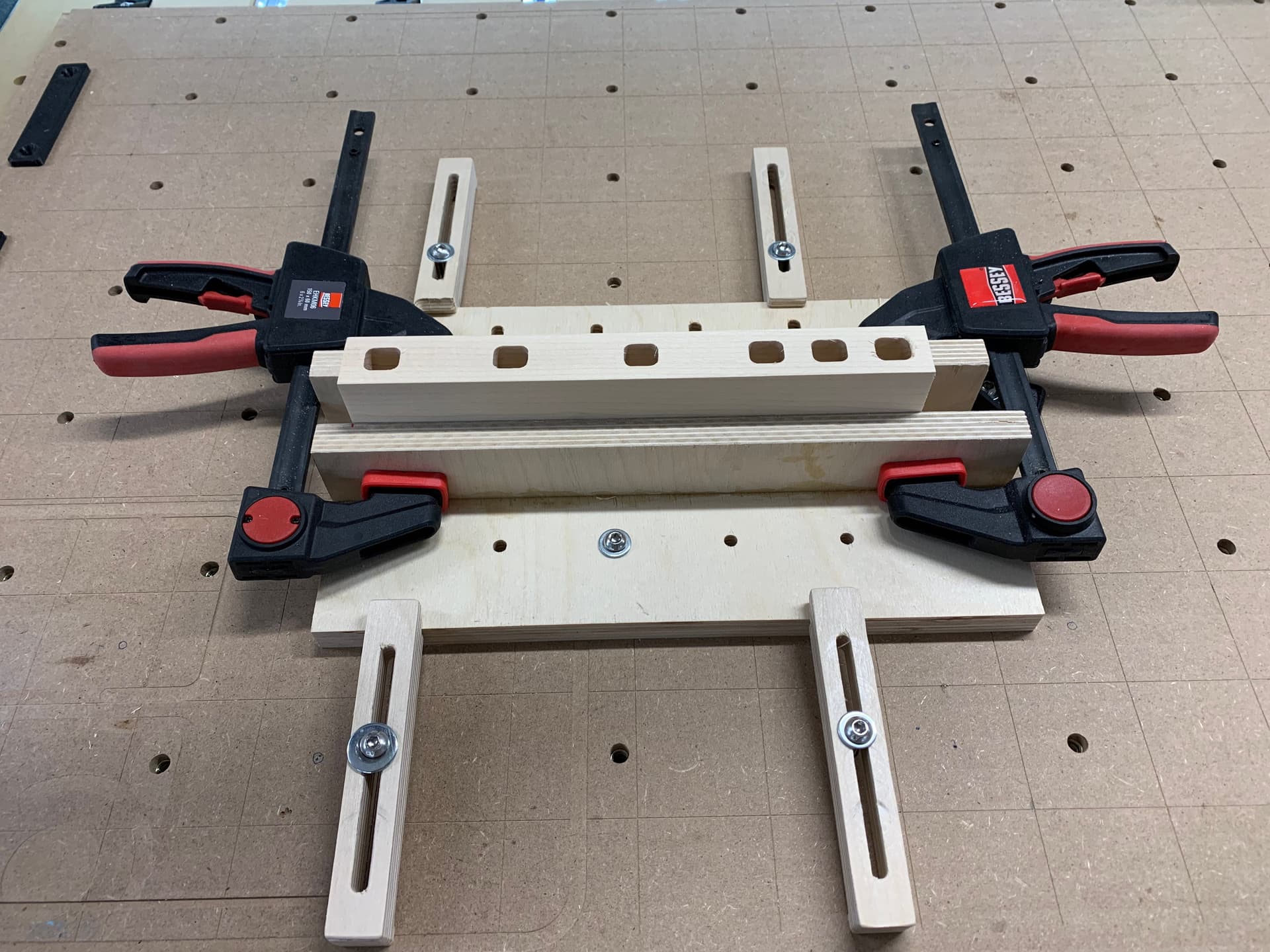
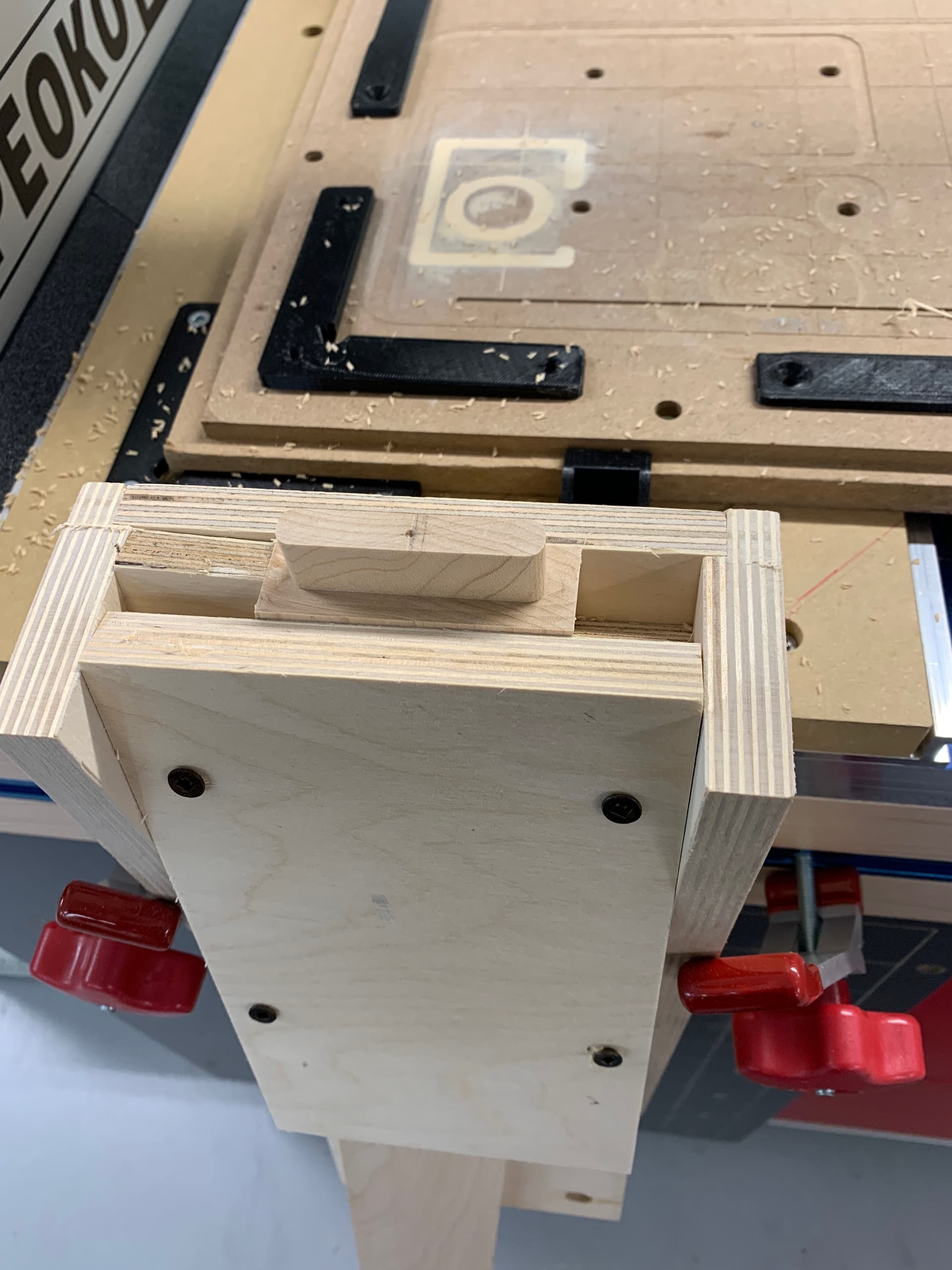
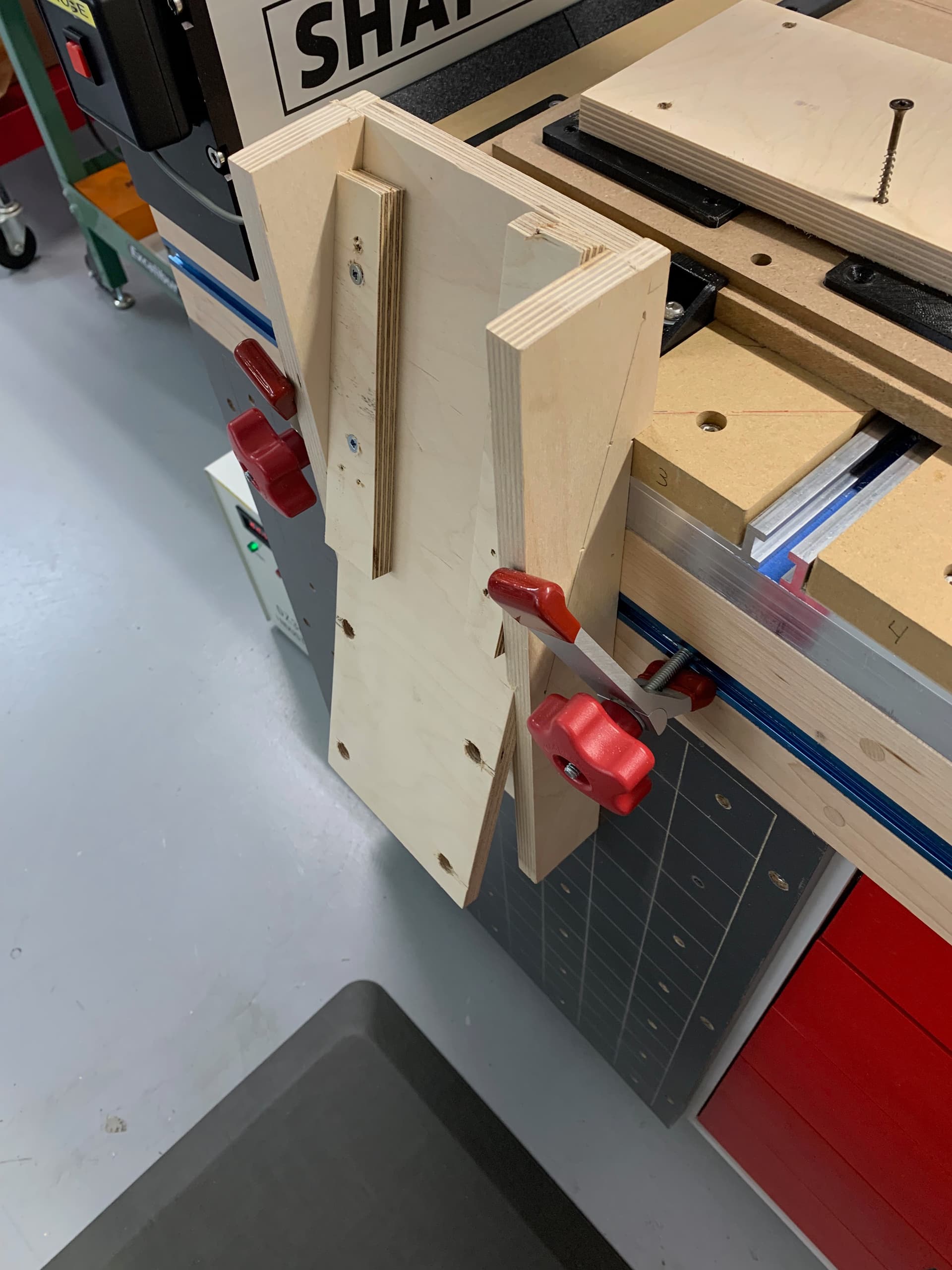
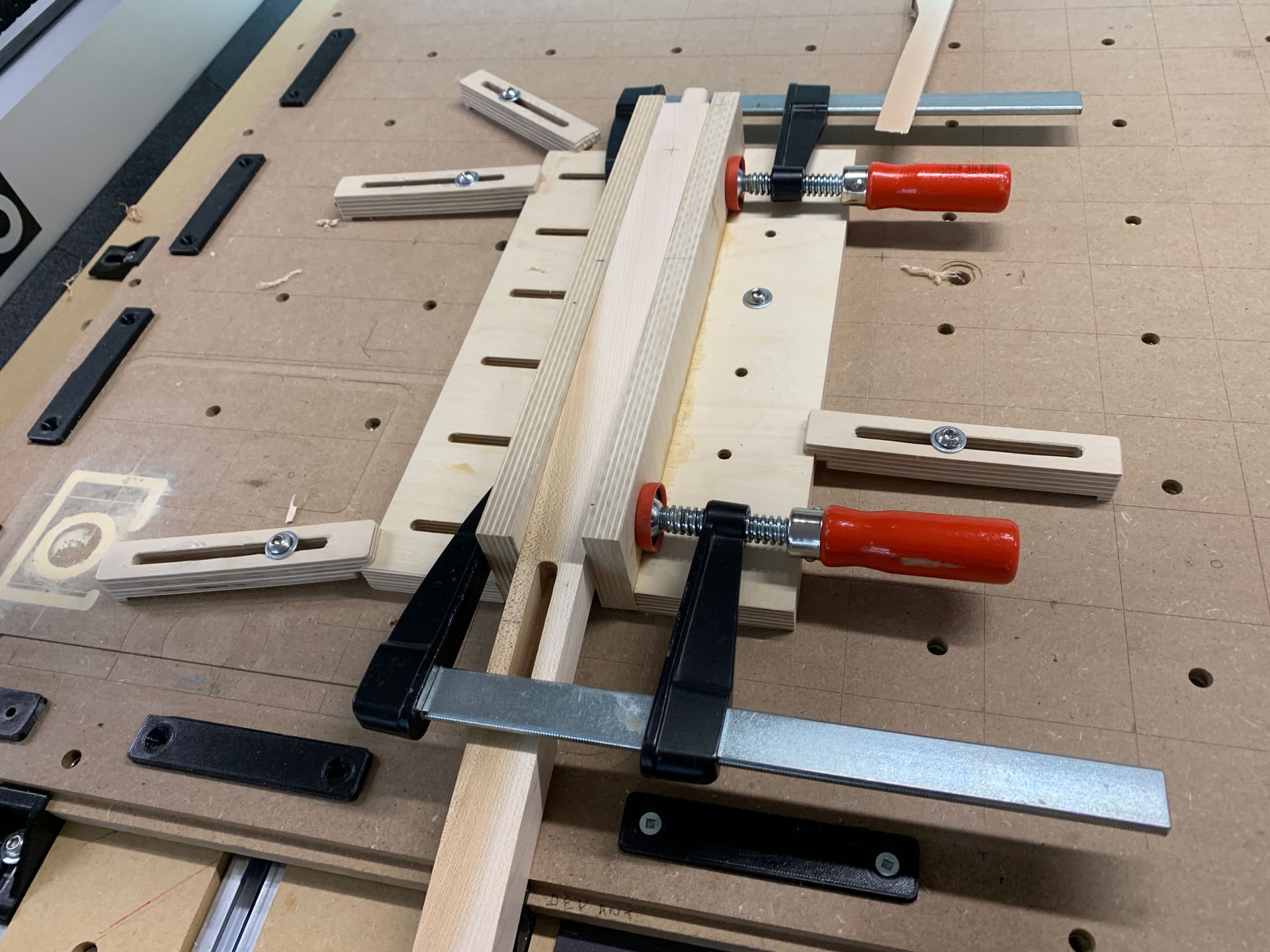
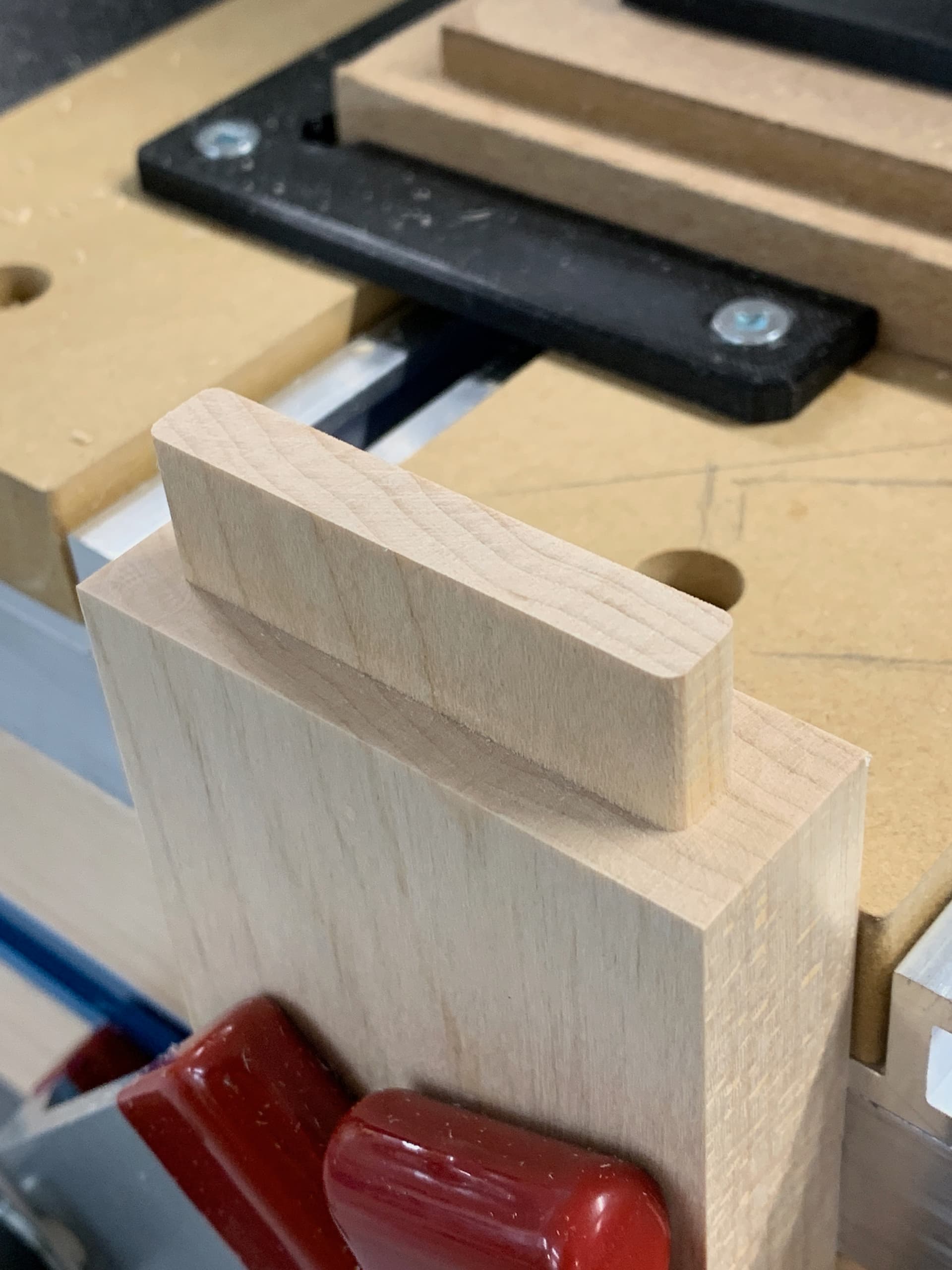
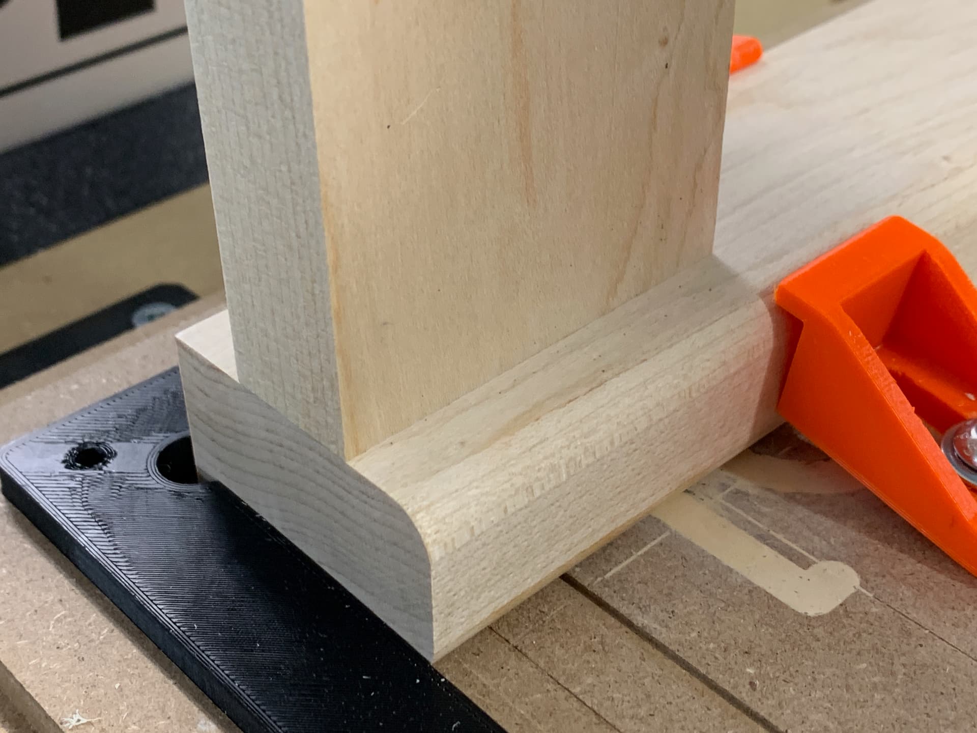
To make the tenons on the parts of the backrest, I made with Fusion360 and the CNC a template for putting the parts vertically at the front of the CNC. One template for the bottom and one for the top. It makes nice tenons.

Next step is easy, the top and bottom piece of backrest. I make the mortises after the tenons, it allows to adjust the mortises to the tenon without moving the part on the CNC table. It’s very simple to remove an extra 0.1 mm from the mortises with the software and go back to the CNC.

Here is the backrest without the roundings of the edges:

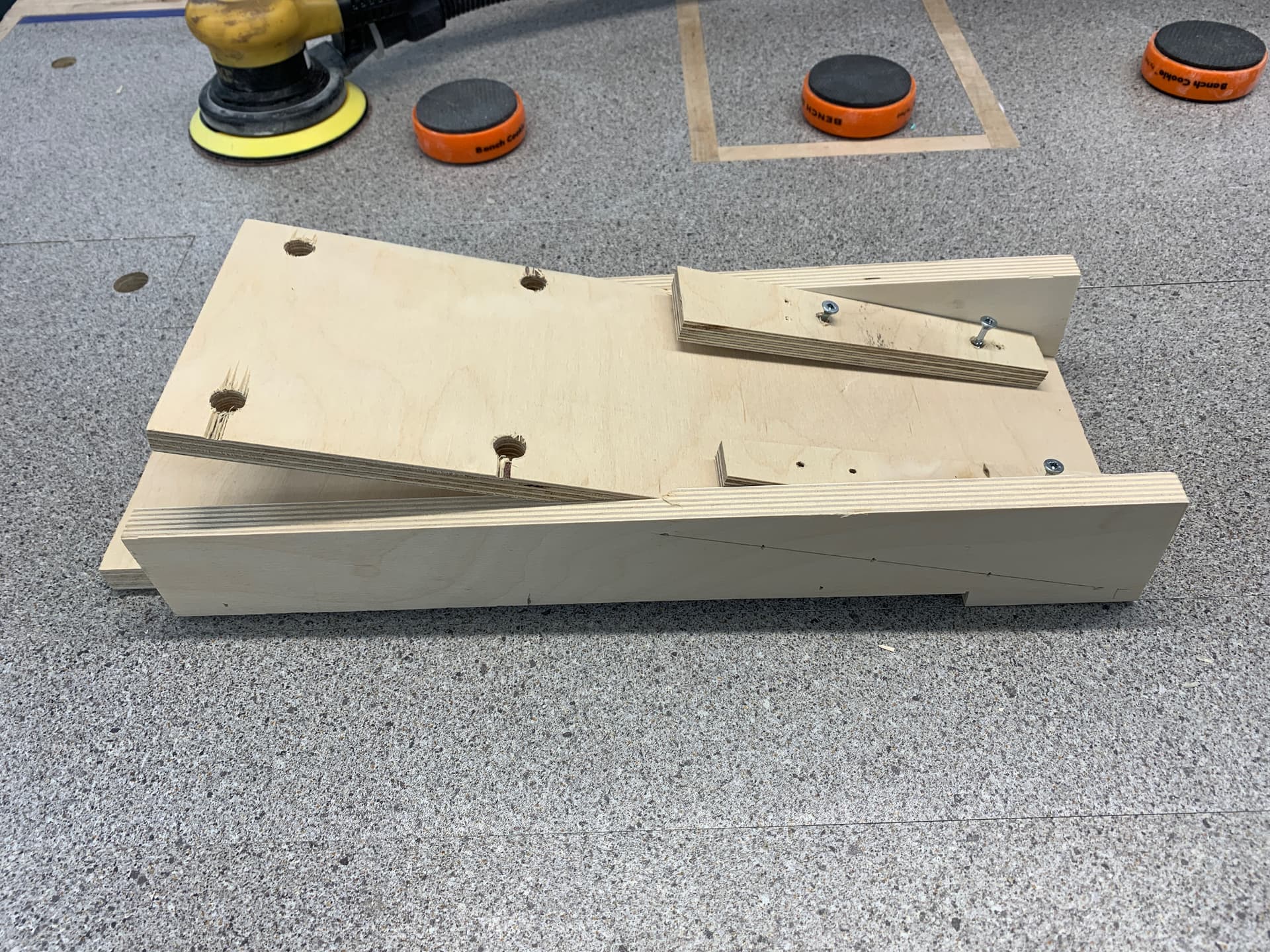
Now the side aprons below the seat. These are compound angles, but the two ends of the aprons are parallel, which simplifies the template a bit. By alternating the two screwed pieces with angles parts, you can make the left and right side.

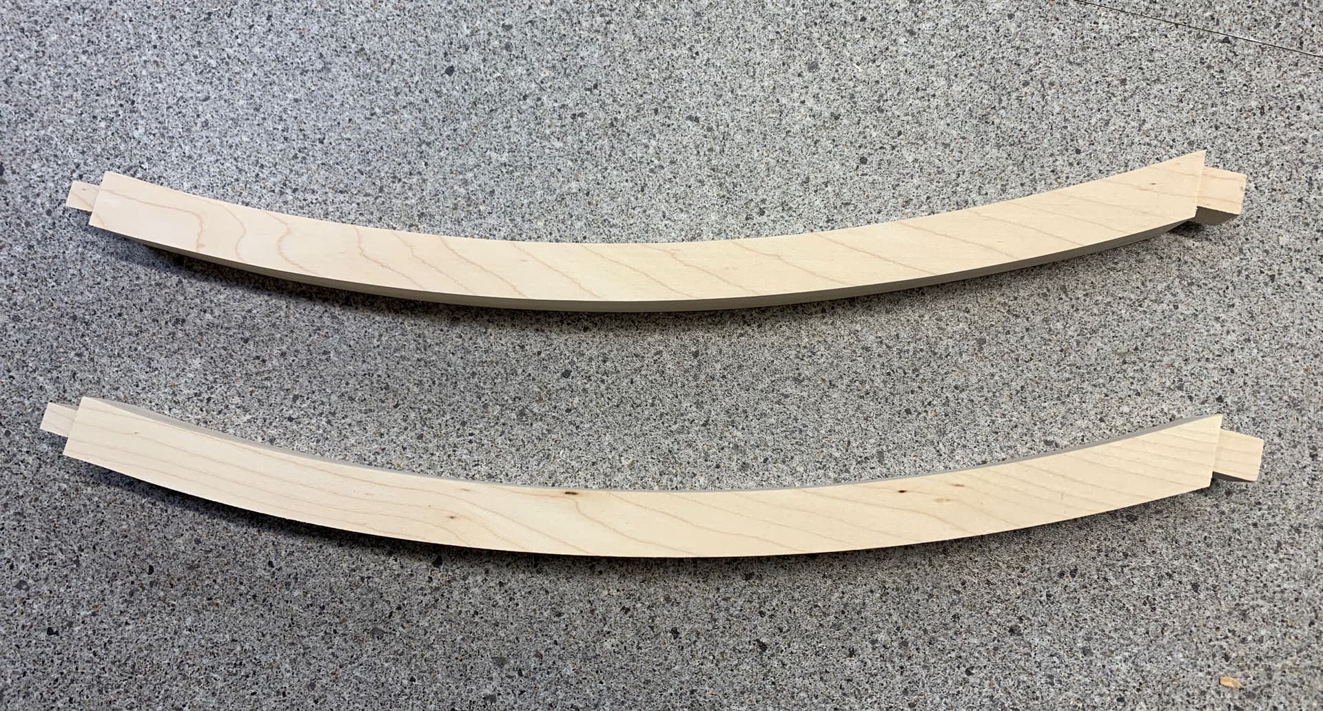
Now the stretchers, pieces also at compound angles, the ends are not parallel and in addition the pieces are curved! I didn’t want to take the previous method of the template. It would have worked, but requiring several complex jigs… I decided to make them mostly with the CNC and finish with a wood chisel, which I don’t have much experience and dexterity… With straight bits, the CNC cannot do negative slopes but can do positive slopes by going in small increments. The approach I’ve taken is to carve the sides of the stretchers up to 3mm from the bottom, carve whatever the CNC can carve for the tenons in steps of 0.5mm down to the bottom of the board. Then I reversed the piece from top to bottom (using indexing pins) to reach the corners of the tenons that became accessible. Finally I finished the size of the sides of the stretchers, leaving a few tabs. There are only small parts with negative angles below the tenons to finish with a chisel. It is also necessary to correct with chisel the curvatures left by the 1/8" bits in the corners of the tenons.

The most difficult being finished, I then milled the mortises in the parts of the backrest. I put the section to be drilled parallel to the table and calibrated the CNC to make mortises centred on the desired point.

The tenons of the front apron are very simple and here is what it looks like without touching up or sanding with a brand new bit:

and the “fit” with the mortise is perfect:

If you’ve read this far you can guess that front leg mortises are very simple to make.

The rounding of the backrest and the legs were made on the router table with a 1/4" round over bit.

Here is the final result, there remains the sanding, the gluing and of course the finish. The reinforcement parts are still missing.

I must say that my SOP is my favorite tool in my shop!

47 Likes

Great job. I like this.

1 Like

Fantastic job and great write-up!
and I love to see a Shapeoko Pro being used with a vertical holding jig, evidence that this is still possible/practical.

1 Like

Excellent work and a detailed write up, the pictures speak a thousand words.

Only 4 more to go then!

2 Likes

You say that so non-nonchalantly. You matched an existing design and even threw in a diagonal fixturing solution. Whew! +1

2 Likes

Hi Julien, thank you for your comment, adding a HDZ mount and a 80mm spindle bring the center of the bit (spindle) to 34 mm in front of the SOP which is ok. More would be better, it was tight making the jig for the apron tenons. In the future, if I would need more clearance for a bunch of tenons, I think I could use like a 1 cm aluminium spacer in the back of the spindle mount for doing the tenons using small cut to put less stress on the machine and then remove it when finish. But would have to do some tramming.

4 Likes

did it take much fiddling to get the diagonal blank set up correctly? your milling is super tight to the size of the stock, very impressive.
ref
image

I did a diagonal piece last night (router template) and clamping it at 45 in exactly the right spot was… interesting.

1 Like

OUTSTANDING WORK!
Very well thought out.
Artistic design is over the top.
Thank you for sharing and showing what can be done with a Carbide 3D CNC.
The jigs and clamps are very cool as well.

Side Note:
Carbide should have an area on the web site for award winning projects showcasing the best of the best.

3 Likes

Steven you are right there was some fiddling doing the setup. I don’t even remember all the process, I almost never write down my work, it has been a bad habit for all my life! But I take pictures… I defined my X0,Y0 at the lower left corner plus 10 mm in X and 10 mm in Y mm. Then I draw some limits lines on the table by making the CNC following the board contour. It was easy then to repeat the process by placing the following boards at the same place. Here is a screen shot from Fusion. The maple board were a little longer than the dotted contour. The holes were not drill on every pieces, some with thru depth some half, they are used for the alignment with dowels for the gluing.

2 Likes

Eric thank you for your kind words. You may have missed in the long text that the chairs are copies of a dining set bought many years ago.

Dude, you still had to redesign how to recreate these using the CNC did you not? Did you not have to create jigs to assist in this venture?
I know how much work I have putting together projects, what you have accomplished is very admirable.
Don’t cut yourself short my friend.
In other words… Take the compliment and run with it! :clap: :crazy_face:

2 Likes

Wow. I wish I had your skills and patience. I am having trouble just getting a simple two sided job to come out right and you am doing such extraordinary things. Thank you for the running dialog and the pictures. You have given me a ton of ideas. Frankly I looked at the first image and thought “how is he ever going to pull this one off?”

Thanks and please share your future projects. Some of the things I see people make here is truly inspirational.

1 Like

Thanks Paul for your appreciation, I take the time to present some of my projects to share what I have learn by practice and a lot from others like Winston Moy and many others. Also I want to mention the immense dedication of Will and Julien on this forum. They have a lot of patience! We leave in a fantastic period to be able to learn about anything on your computer at home. So much information available, videos on YouTube, plus great home affordable tools like 3D printers, CNC machine. There are also bad information info on the net but this is another subject…

Six years ago I didn’t knew nothing about FPV racing drones. A year or two after learning from YouTube, I was assembling my own drones from parts bought online and designing parts for them on my 3d printer. I must say my background is electronics engineering, but some friends at my club have done the same without my background. Now one year after I got my CNC I was able to realize this project that I would not undertake with my woodworking tools even it was possible.

I don’t consider my self skilled with hand tools like chisel, hand saw… but with good tools, jointer, planer, band saw, and now with computer controlled tools with some CAD/CAM software and some thinking there is almost no limits!

I am glad if I inspired you and others, there is a lot of very great projects and ideas on this forum from other peoples. We all learn from each others…

6 Likes

Wow, fantastic! I really appreciate all of the detailed photos.

1 Like

Fantastic piece. Beautiful and well thought out. Thank you for sharing.

1 Like

Beautiful job! I love the fixtures.

1 Like

Amazing what can be done with these machines, The limitation is only ones imagination.
Brilliant piece of work and great informative write up with lots of pictures…Well done

1 Like

Awesome write up, and great looking chair!! Any issues with strength of the chair back? Being end grain I’d imagine it’s slightly less robust.

Great work! Dig it!

1 Like

Inspiring. Well done, beautiful piece.

1 Like

Thanks Corey, I didn’t not applied the finish yet, here the month of May is the outside spring cleanup and season switchover so it is quite busy. Since I made a copy of my originals one bought almost 30 years ago, I think they will be ok. They are made of maple which is a hard wood. The bottom of the back has the biggest load which is in axial compression, the top part has much less load and can bent a little if someone applies pressure with is back.