I’ve been a viewer of this community for a while but never participated. After 2 years of having my Shapeoko Pro, I think it’s time to jump in and share.
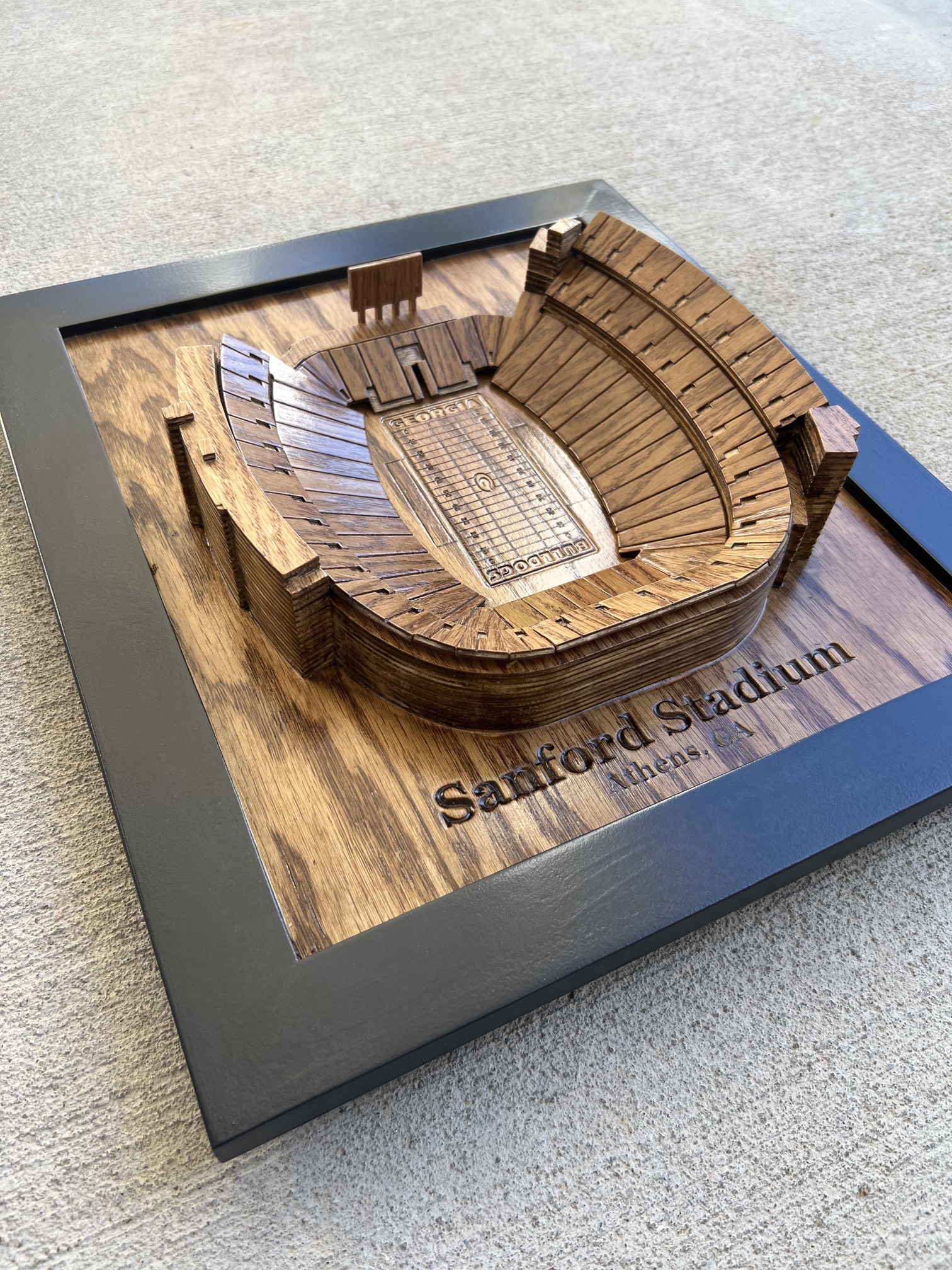
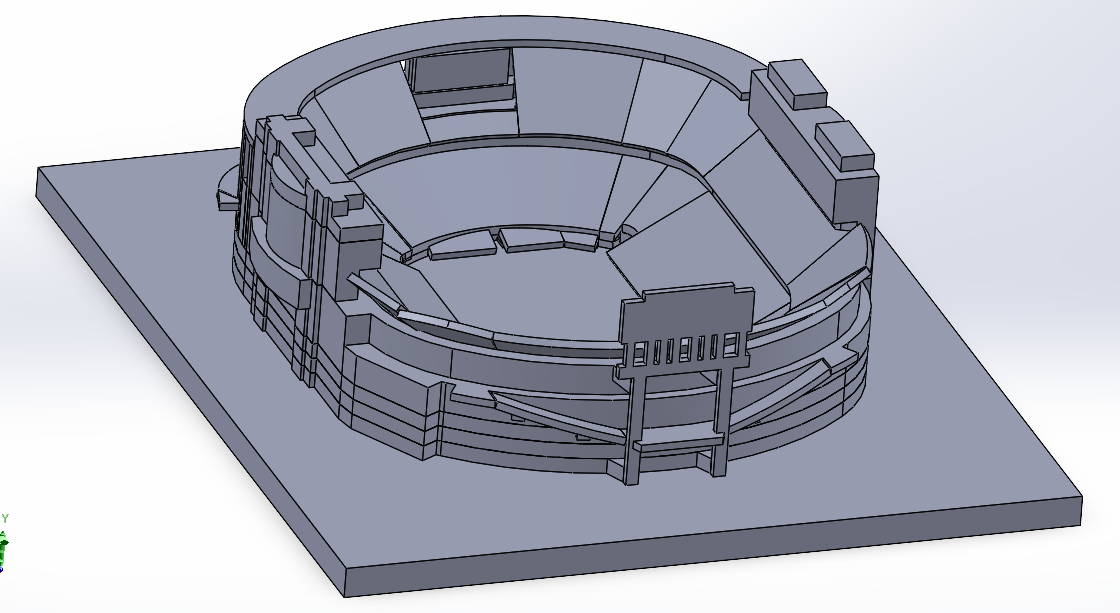
I recently completed these two 3D stadium builds for some family. First one is Neyland Stadium (Univ of Tennessee) and second is Sanford Stadium (Univ of Georgia). I programmed all of the 3D geometry in Solidworks and exported all of the .dxf files to CC.
Backing board is 1/2” oak plywood, each layer of the stadium is 1/4” oak plywood, and the seating pieces are 1/8” oak plywood. Used a combination of the 502 PCB engraver and 122 1/32” end mill for the details, 112 1/16” end mill for contour cut outs, and a 302 V-bit cutter for the lettering. All of the pieces were cut out on the Shapeoko except for the frame and the overall length and width of the backing board.
One area I need to work on is work holding on the 1/8” plywood. The depth of the detail work varies because of the bowing. Doubled sided tape might be the answer, but I’m afraid that the tape would damage the veneer.
Anyways, these two projects were an absolute blast to design and build. I’m seeing more stadiums in the future.
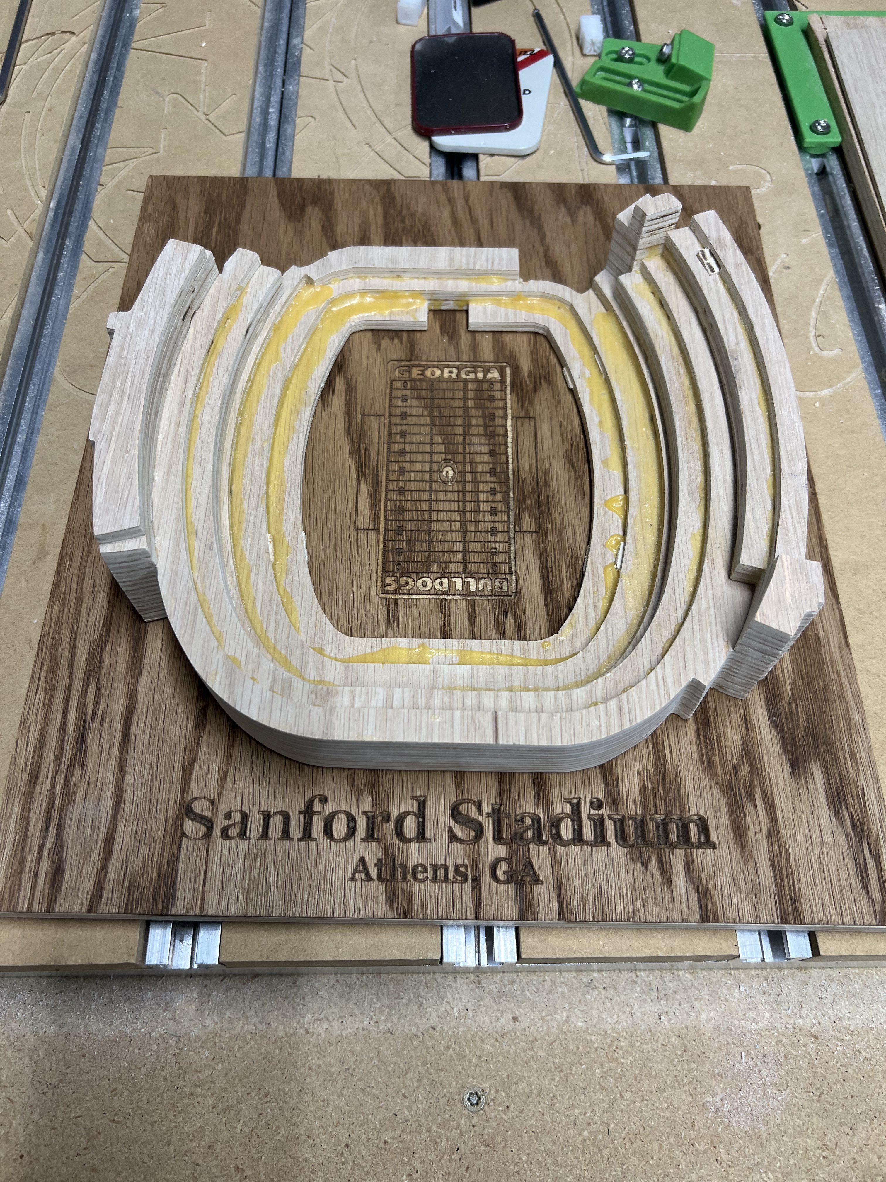
Lessons learned from the first iteration, I added anchor stakes inside the stack to keep everything lined up and also have a reference point on the backing board. In the first iteration, when I glued the stack up, the glue caused the plywood to creep and alignment became an issue. I ended up having to do one level at a time in order to keep an eye on the movement. With the stakes, I can glue up the entire stack in one process. Here you can see the stakes coming out of the bottom:
I apparently deleted all of my in process pictures of adding the seating, but I will post those once complete. Some of the seating pieces get bent to fit a curve. The 1/8” material is perfect for that.
I’ve never been to Neyland Stadium and I’ve been to Sanford once, but didn’t see much of it. So everything was done via Google Maps, Google Street View and images on Google. I took a screen shot of the aerial view on Google Maps and used that as a reference for the overall shape and spacing. Then used images to create the rest.
Very cool and meticulous!! Great job with the concept and bringing it into fruition. As for holding down the 1/8" plywood have you tried painters tape and crazy glue? The painters tape would come off a lot easier than double sided tape.
Of course, I’ll take a shot at it. No past experience with the exception of CAD software. My background is engineering, so Solidworks is what I used to model it.
I dropped this image into Solidworks and used this as a guide to create a 2D footprint of the stadium features. Once that was built and polished up, I used the “Google Street” views to get the 360 degree view of the stadium from multiple vantage points. Neyland Stadium had quite a few views available so it was like I was able to walk around the stadium.
If you notice, the 360 degree “street view” was taken in 2014, so it doesn’t capture changes within the past 10 years. That is where I go to Google images to find recent pictures. For instance, the scoreboard on the northwest end of the stadium didn’t exist in 2014.
At this point, it is really just free hand to try to match the stadium design as close as you can.
The painters tape is a great idea. I’ve used painters tape on the plywood for other purposes and it doesn’t damage it at all. Thank you for the suggestion!!
I enjoyed your post very much. As a UGA grad I was very interested in the Sanford stadium build. I’d like to attempt it but have no clue where to begin. I don’t know Solidworks and do not see how you used Google maps. Would you consider making a tutorial or something similar? Also can a SO3 basic handle such a build?
Any help you can provide would be most appreciated.
This is so incredibly cool. Absolutely beautiful. I would love to work on the Ohio state Horseshoe. I’ll be watching this and more threads to learn the ways. Thank you for sharing.