machine lifts and homes Z-axis (if need be, it will slightly back off of it)
machine begins moving towards the back right corner to home X- and Y-axes
if the machine reaches the switch on one of those axes it then continues in a straight line looking for the other switch
the machine finishes homing at the right (X), back (Y), top (Z) corner establishing the machine origin
in current versions it will then move forward to the tool change position
If you then change/load a tool, or interact with Z-axis zero in some way, the machine will go to the BitSetter to measure the currently loaded tool.
The notice you are getting is a warning as noted at: Carbide Motion Bounds Checking Usually it is caused by a mismatch between job setup: Job Setup and how origin is set relative to the stock: Movements and Zeroing — I find that opening the .c2d file up and drawing a box which matches the specified dimensions (draw up the cut in profile if need be) or moving the machine to the origin and then using a tape measure to measure out the dimension(s) in question will make clear where things aren’t lining up.
I tested with a warm up. Are there any other settings I need to configure on that box? It’s blinking 5 and there’s a dial, which I’m not sure what setting.
For more on the VFD, if it’s not in the manual, check in at support@carbide3d.com w/ someone who is familiar w/ them (I bought a different spindle back before ours was available, and due to space constraints haven’t had occasion to ask for one).
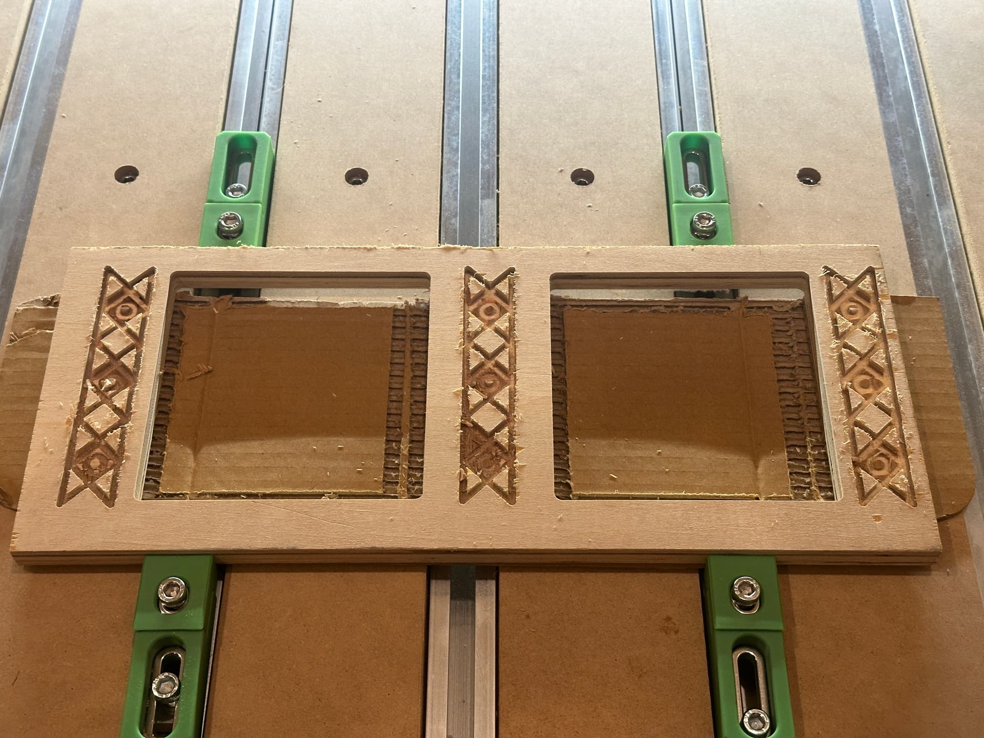
Not perfect, but we were able to cut two squares and add some detail design work without breaking anything…or burning down the house.
I forgot to adjust the depth per pass on the design, so it tore out, but overall it was a fun learning experience. One almost dangerous experience was that the inner squares I cut out (all the way through) started flopping and flying around as the last pass was breaking through…and that caused some pieces to fly out and throw off the cut a little.
or some other workholding method which will keep them secure — alternately, for my part, any internal element which is too small to be a useful piece of stock for a future project gets machined away (my time is more valuable than the machine’s).
This seems like a good suggestion - could you say this with a little more detail so I can be sure I understand? What I think you are suggesting is to create some sort of fence that the machine knows as square and then put my square stock against that, right?
I’m not quite sure I’m clear on how to best accomplish making the fence and then keeping that reference as I begin a new job? …or does it need to be one job, but pausing and placing the stock agains it.
drawing up a contour or pocket and assigning a toolpath to cut away the recess: Hello Contour or the following section
but pretty much any approach is valid — my recommendation is to get a couple of pieces of scrap and try out different techniques until you arrive at one which you feel suits how you wish to work.
It’s just another way to align a precut square(d) blank with the axes of the machine.
placing the dowel/tool at X-0.125 and Y-0.125 establishes the XY zero while also aligning the stock, and doesn’t require clamping additional fences or guides.
There are many ways to do an alignment. If you’re doing multiple parts you would want something more permanent. If you can’t clamp on top you’d want a different solution.
Just one way to skin the cat.
In addition, to check if the part edge is aligned, I will move the spindle down along the edge.
I move the spindle away from the part a known value, move the spindle down the edge and then move it back and check if the part is leaning on the part
If the machine is powered off, or I had to re-initialize the machine, I will reset everything.
It maybe overkill, but it makes me feel more comfortable.