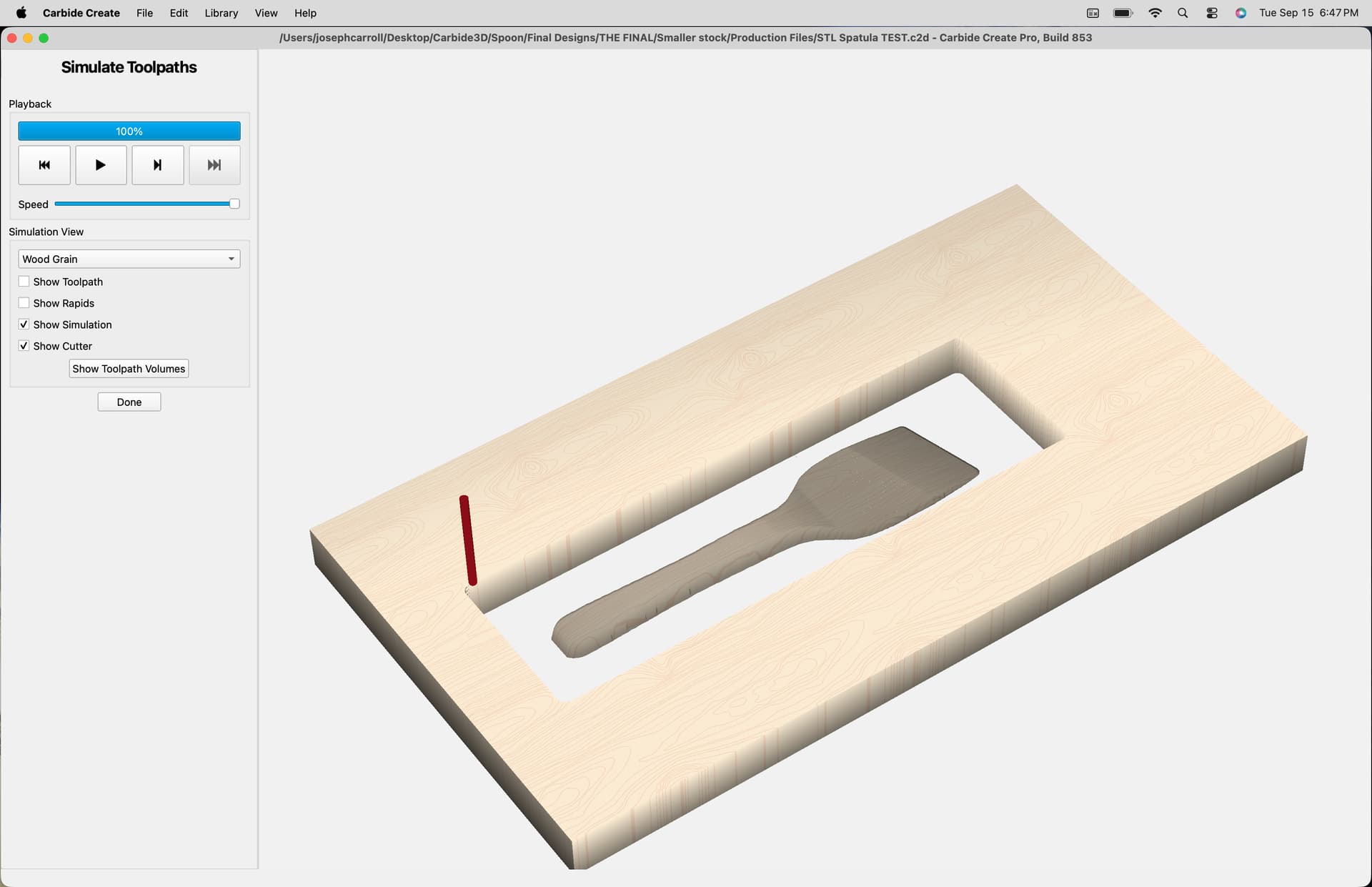
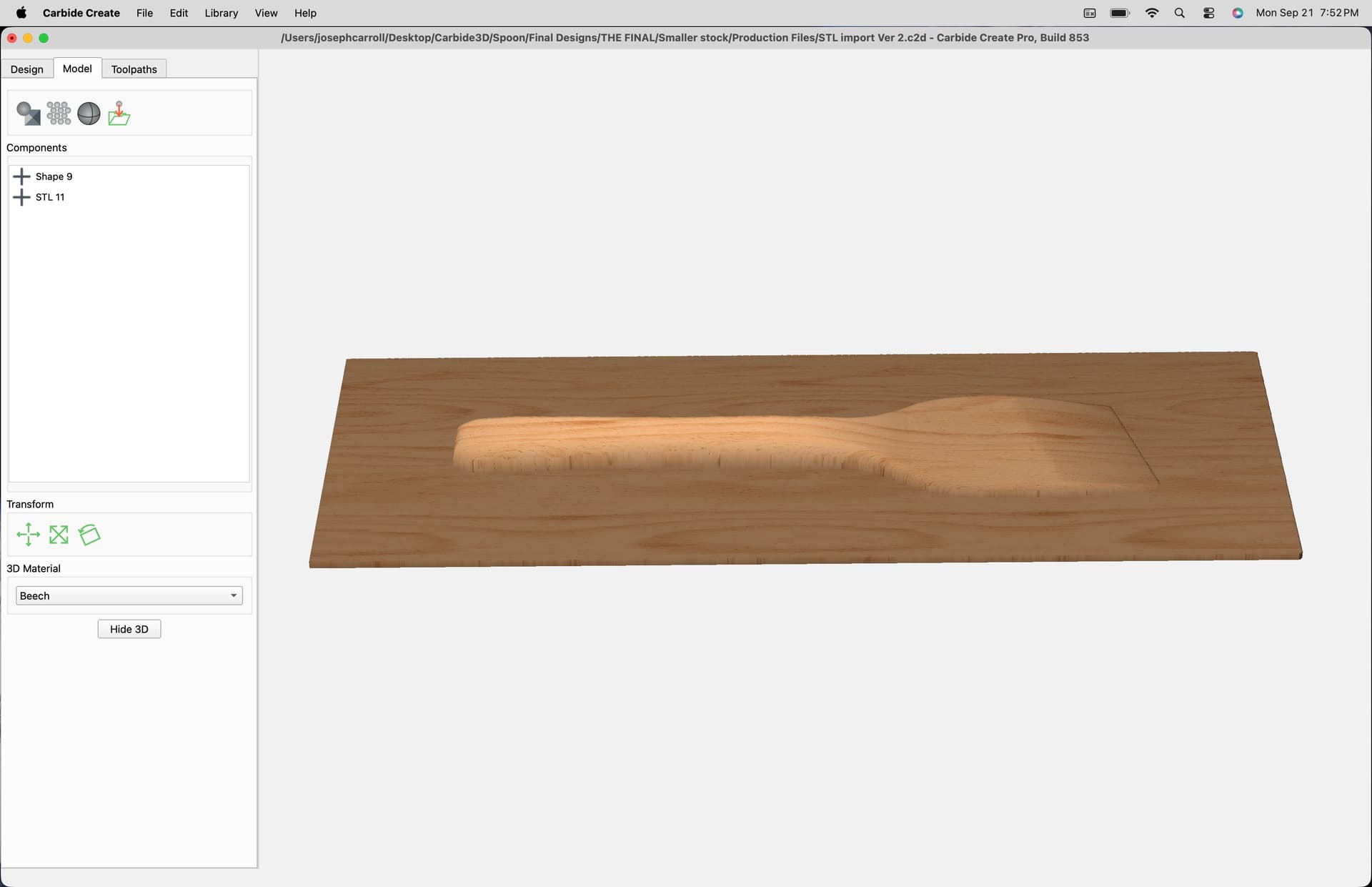
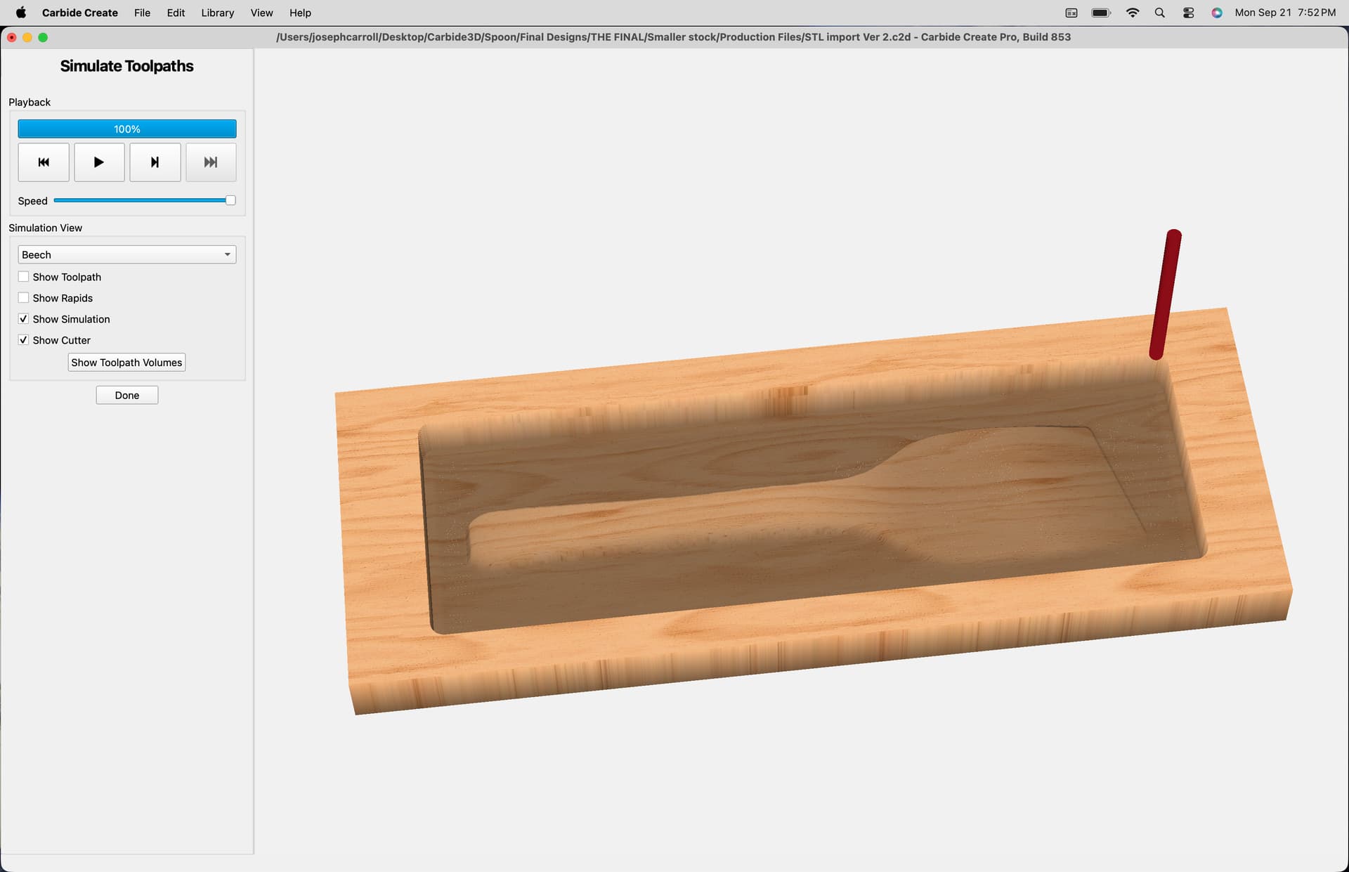
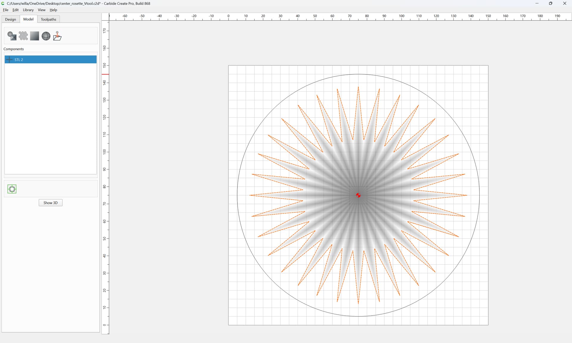
I’m now venturing into the world of STLs. While I figured out how to import and run the tool paths for one, I’m at a loss now for how to hold the piece in place once carved. Tabs? If so, how? Something else?
Any advice would be appreciated.
Thanks!
I’m now venturing into the world of STLs. While I figured out how to import and run the tool paths for one, I’m at a loss now for how to hold the piece in place once carved. Tabs? If so, how? Something else?
Any advice would be appreciated.
Thanks!
There are a couple of possible approaches:
Note that for the more complicated two-sided options, MeshCAM might be a better CAM option.
If you’ll upload the file and let us know the details of the project we might be better able to advise.
Thanks Will. This will only be a one sided carve so I am leaning toward tape and glue for just double sided tape.
It’s a small tapered kitchen spatula.
I’ve included a link to the file, as basic as it is, in case anyone is interested.
I have used tabs and tape/CA glue. In this type of carve tabs would be my choice. I would use 3 in this case, 2 offset on the handle (1 per side) and 1 on the spatula end itself. Then a quick sanding off.
Thanks @redlander, I will give tabs a shot but am currently not having much success including them in the design. I will report back later…
I should have mentioned I am not using the contour cut profile yet.
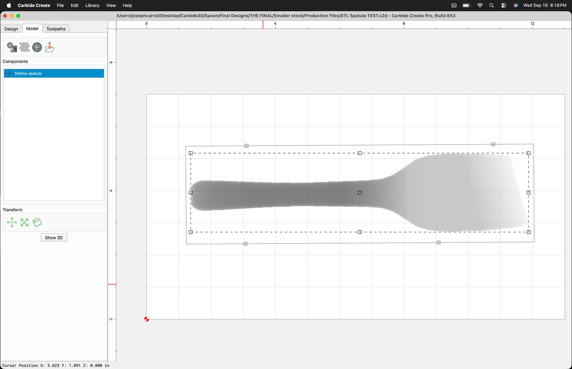
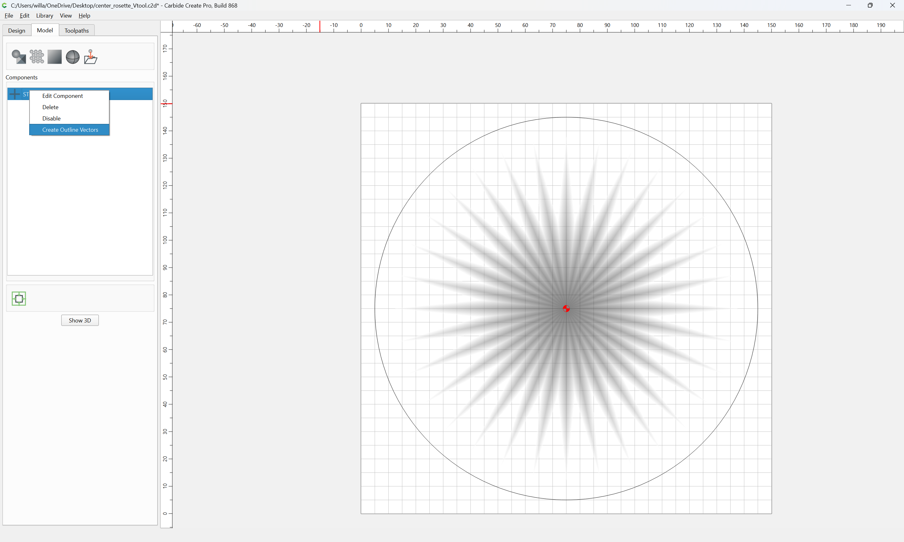
SO here I am, stuck. I’ve imported the STL and as expected, it came with generated geometry around it. I’ve read a lot of different information on here but to no avail. I thought I would be able to design tabs from the imported geometry to the actual outline of the shape of the STL. No such luck. What am I missing?
Thanks
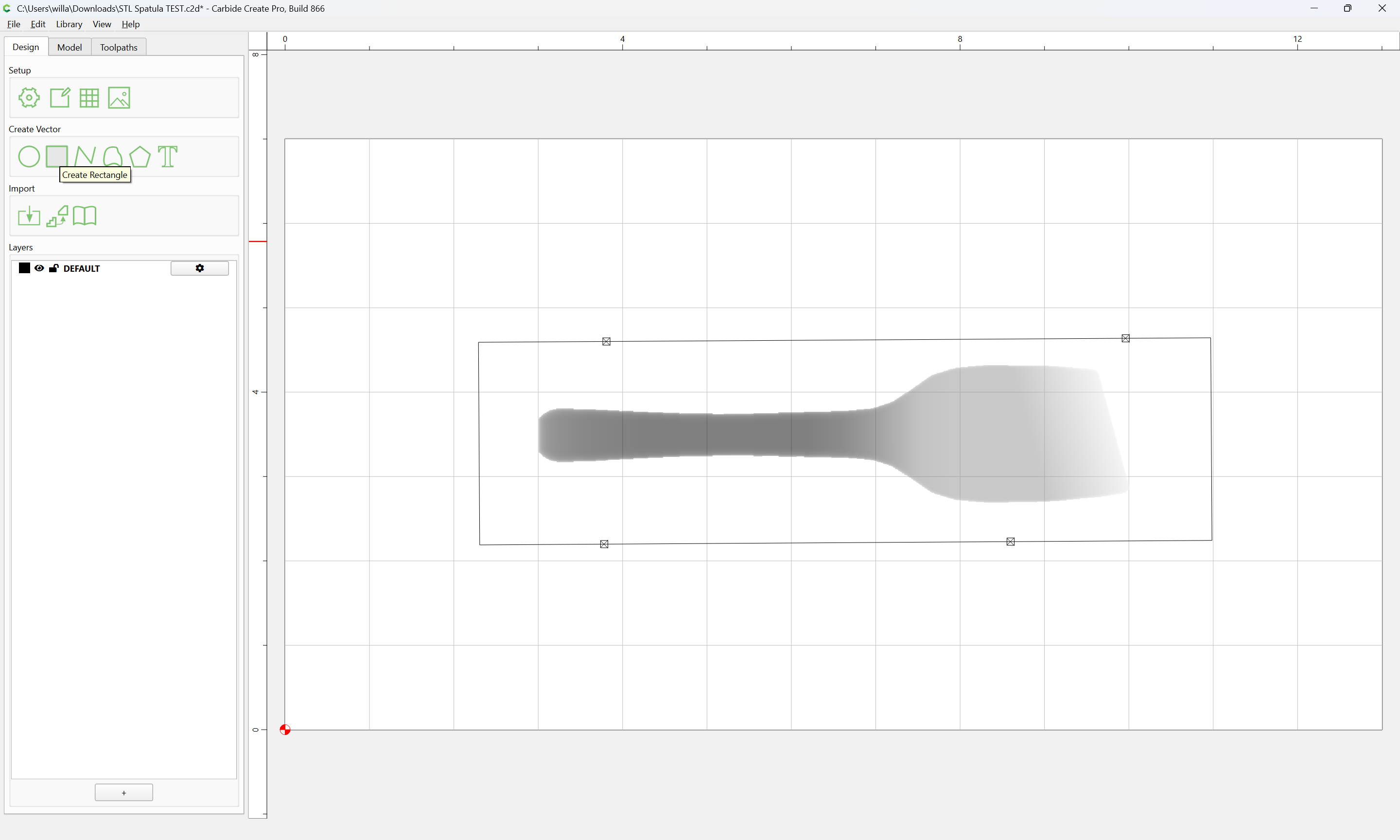
Open the file:
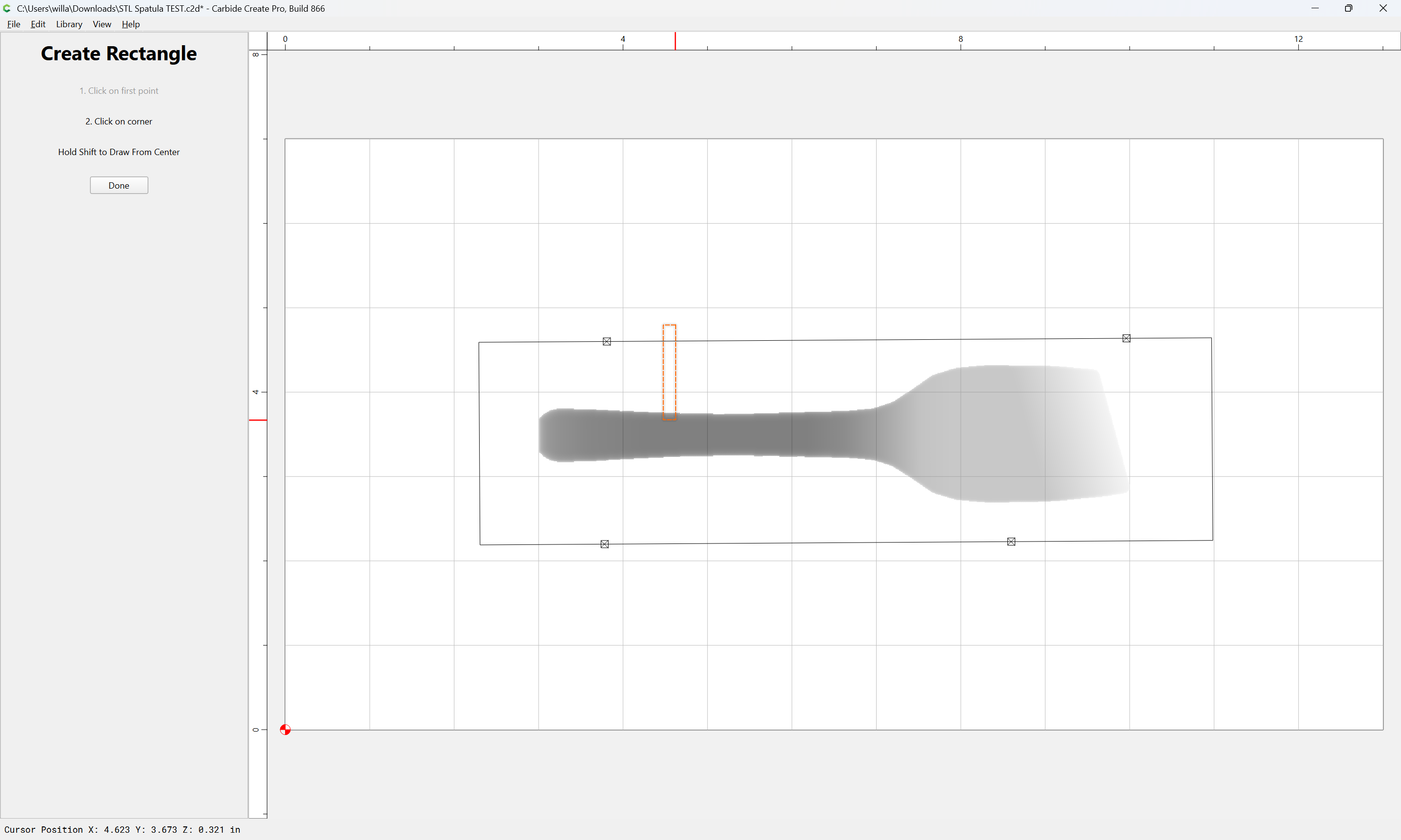
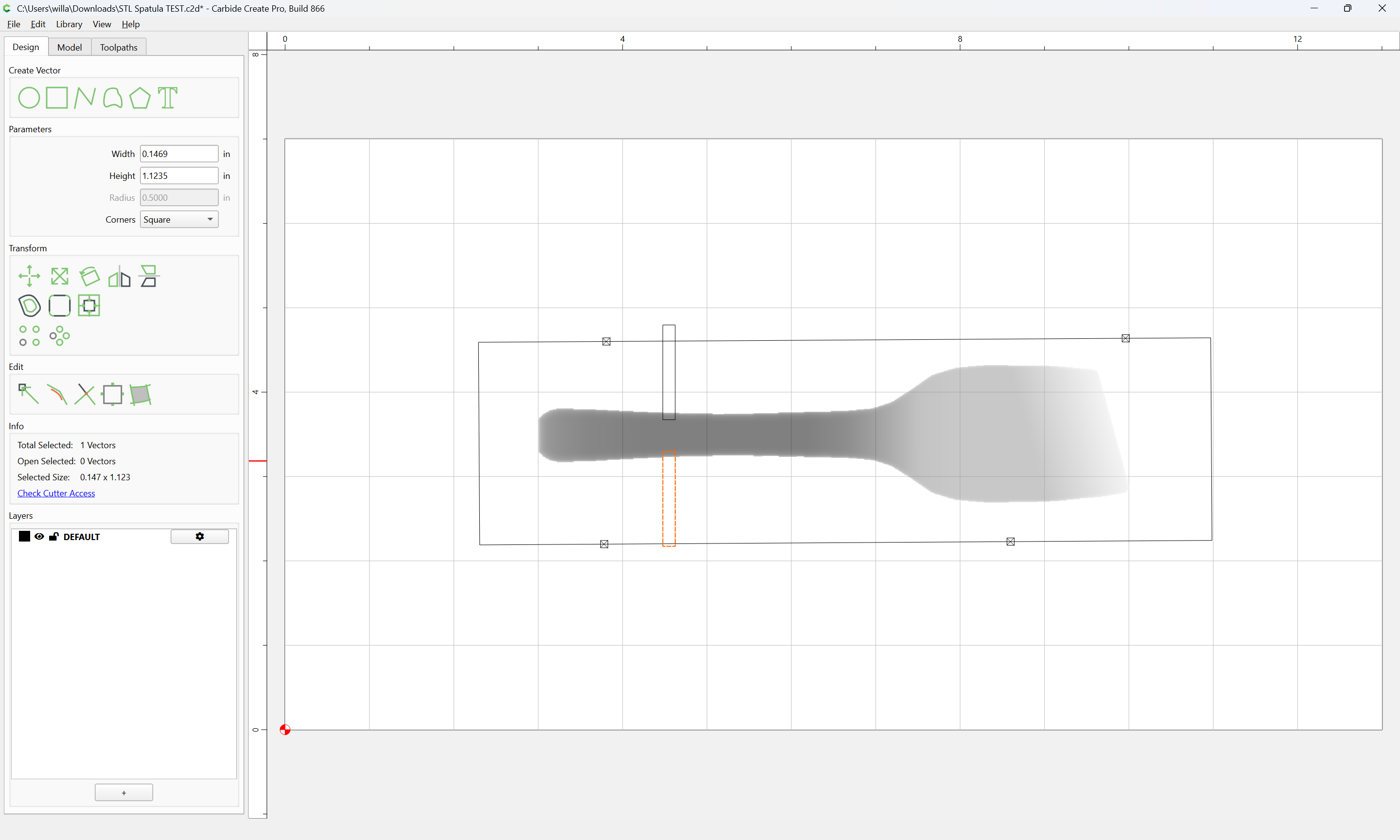
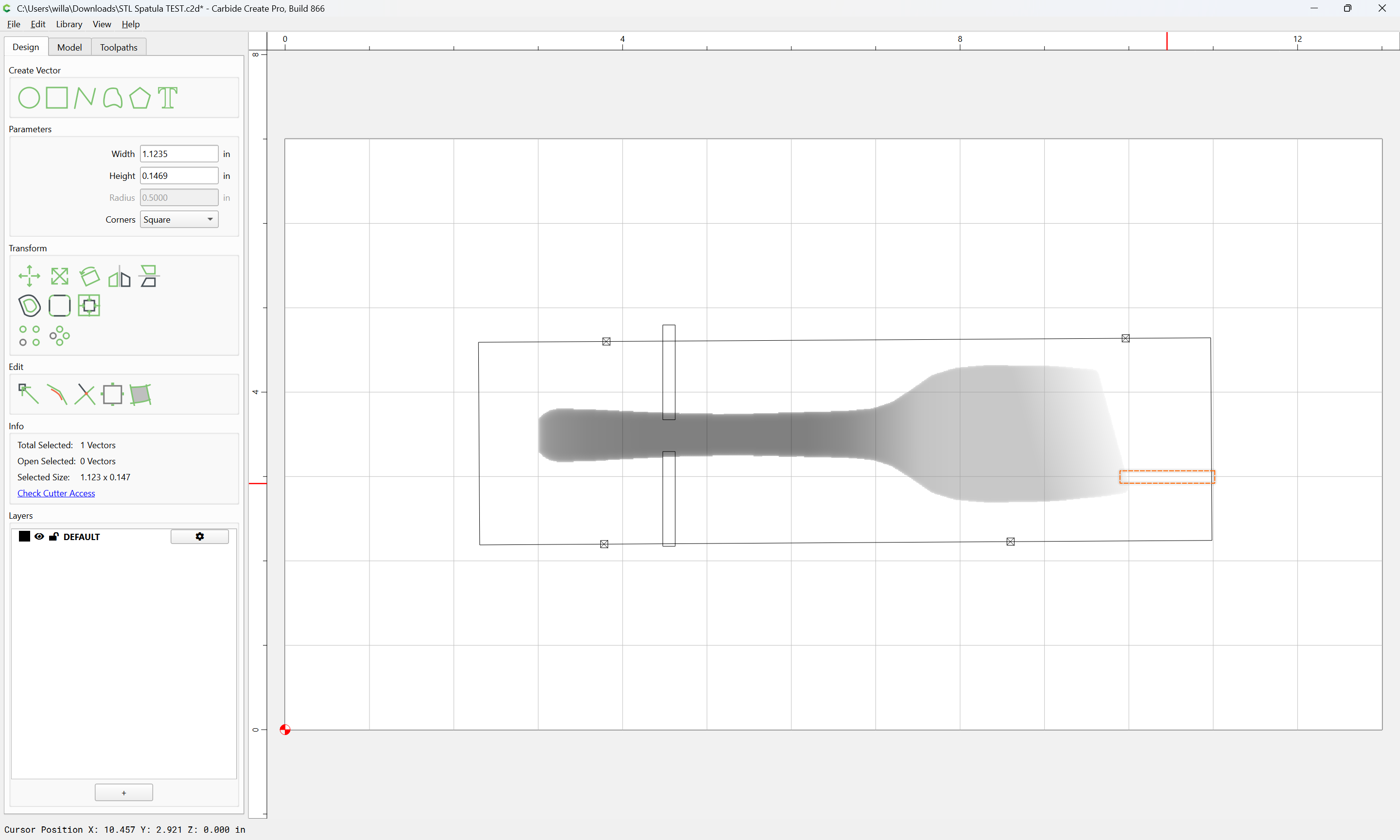
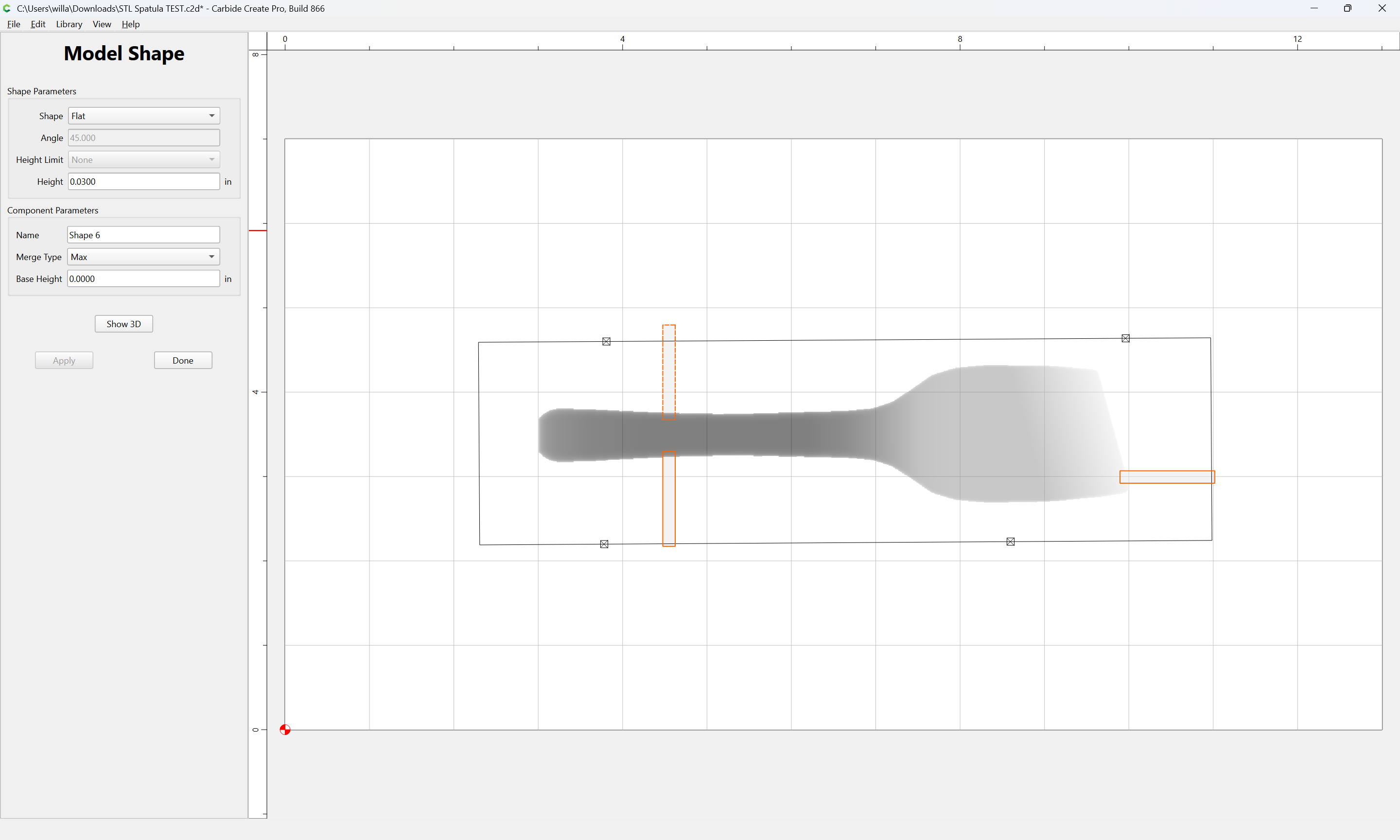
draw in rectangles where one wants the tabs:
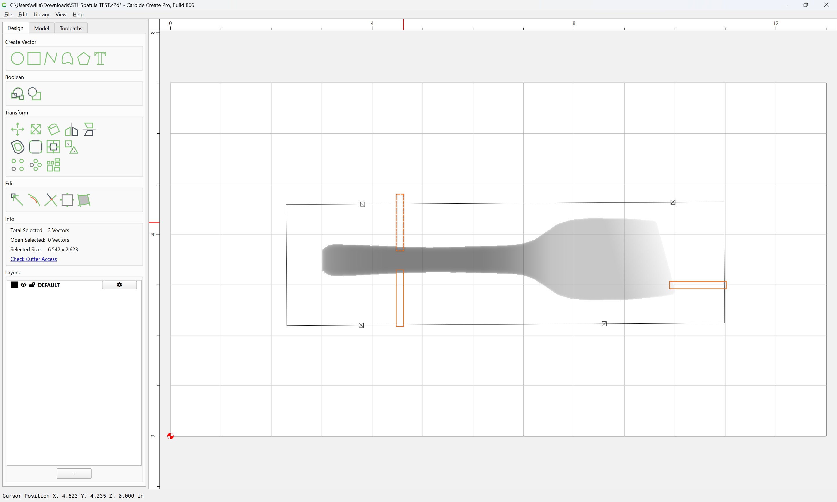
Select all of the rectangles:
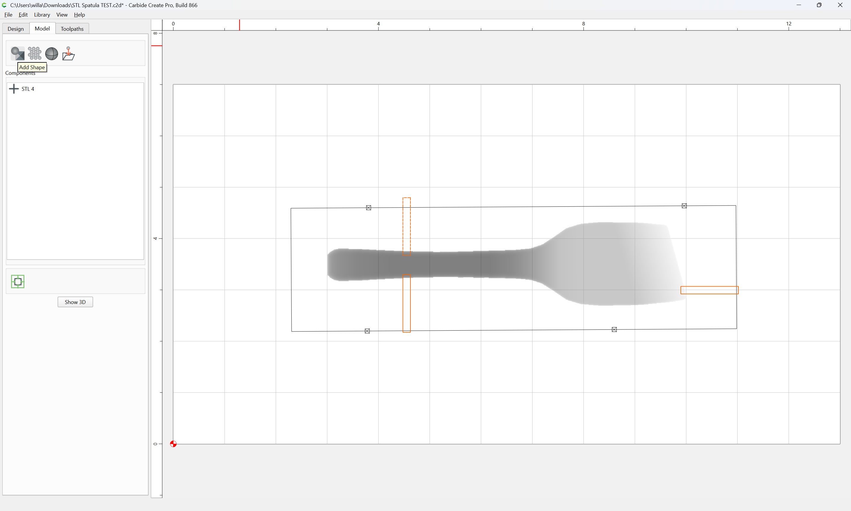
Switch to the 3D Model tab:
Add Shape
making suitable selections
Apply
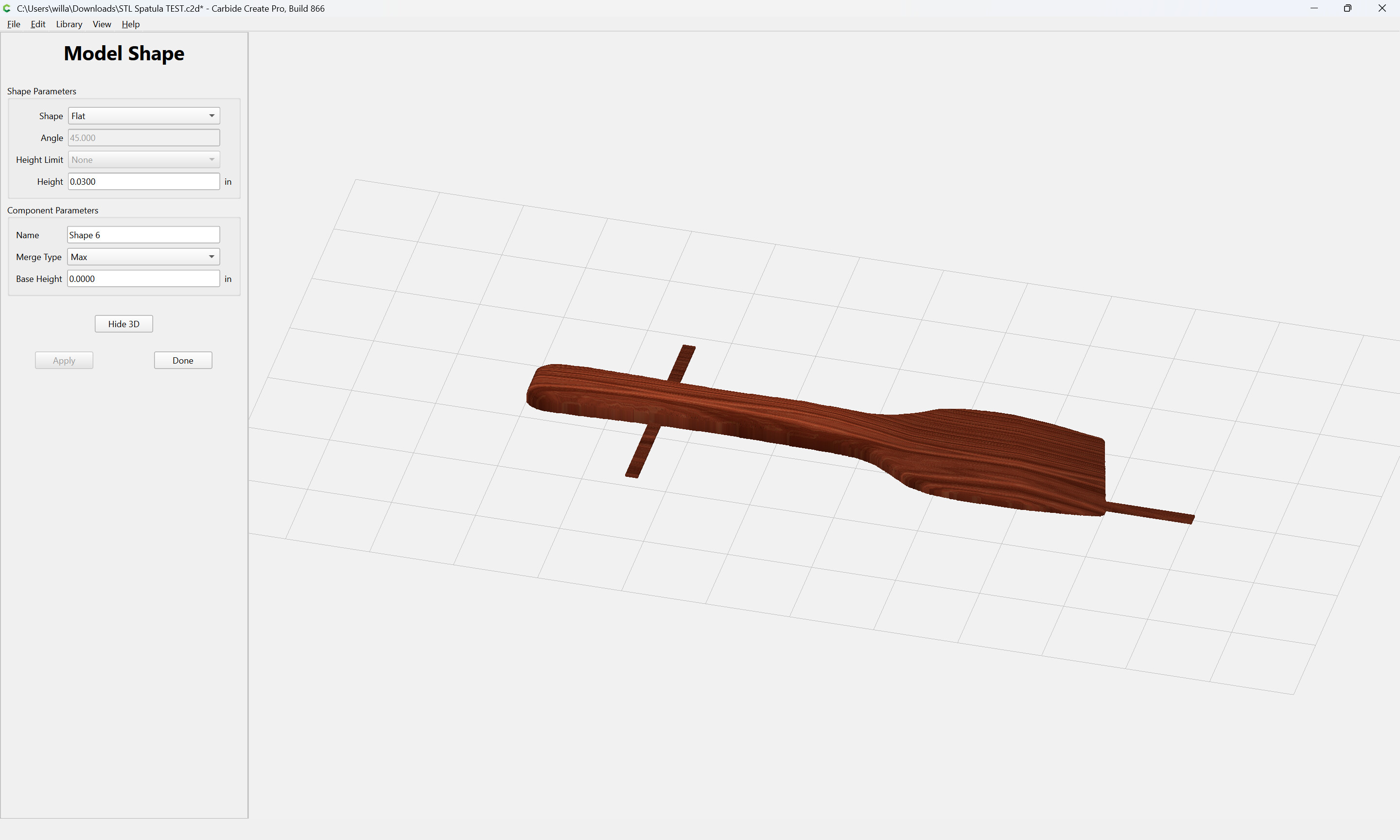
Show 3D
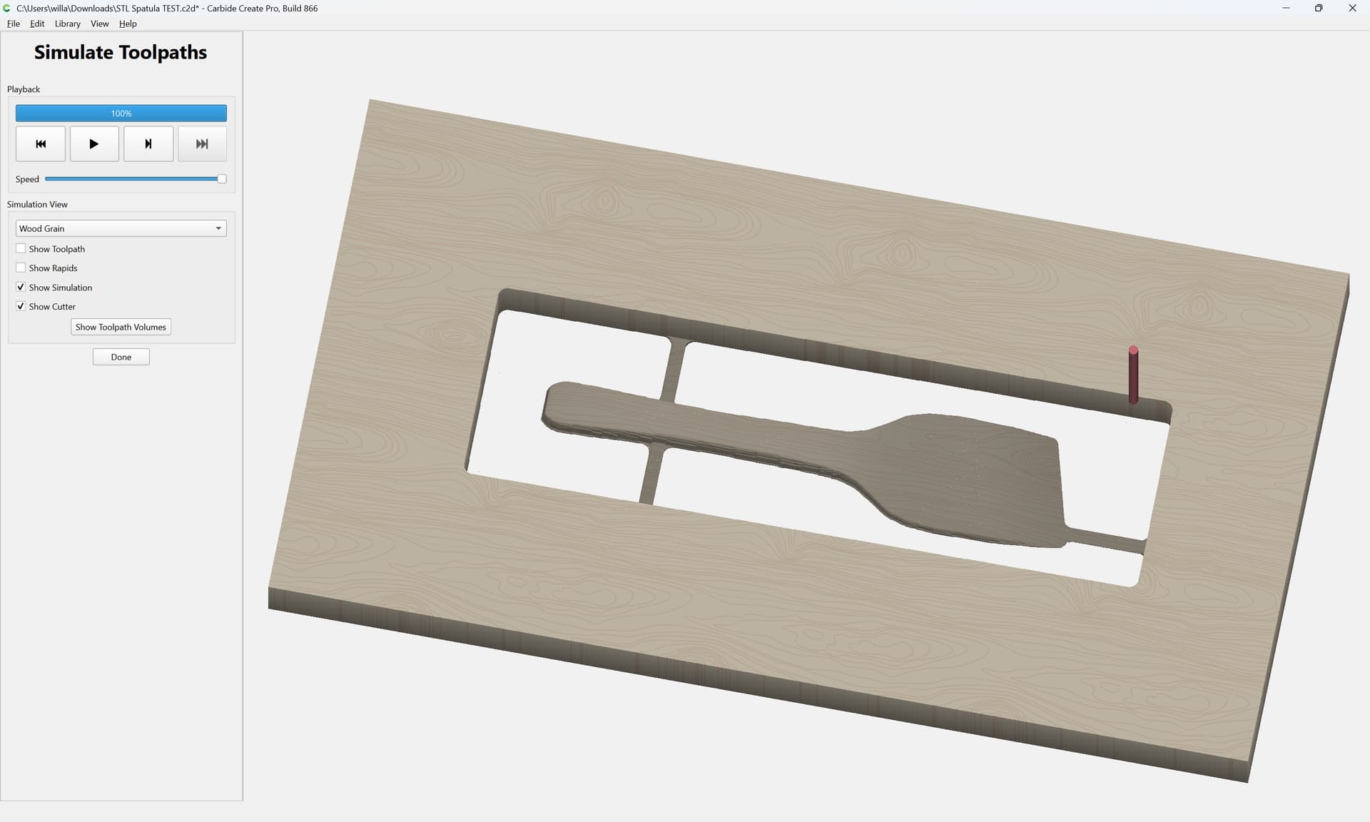
and then so long as the geometry around the shape is not beyond that which was added:
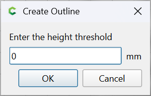
Thanks Will. I realized this would work late yesterday before seeing this. I guess I was actually looking for a true vector outline around the STL. This is a whole lot easier than I had conjured it up in my head.
Looks like this should work. Now that I’m just beginning to understand STLs, I see a huge benefit.
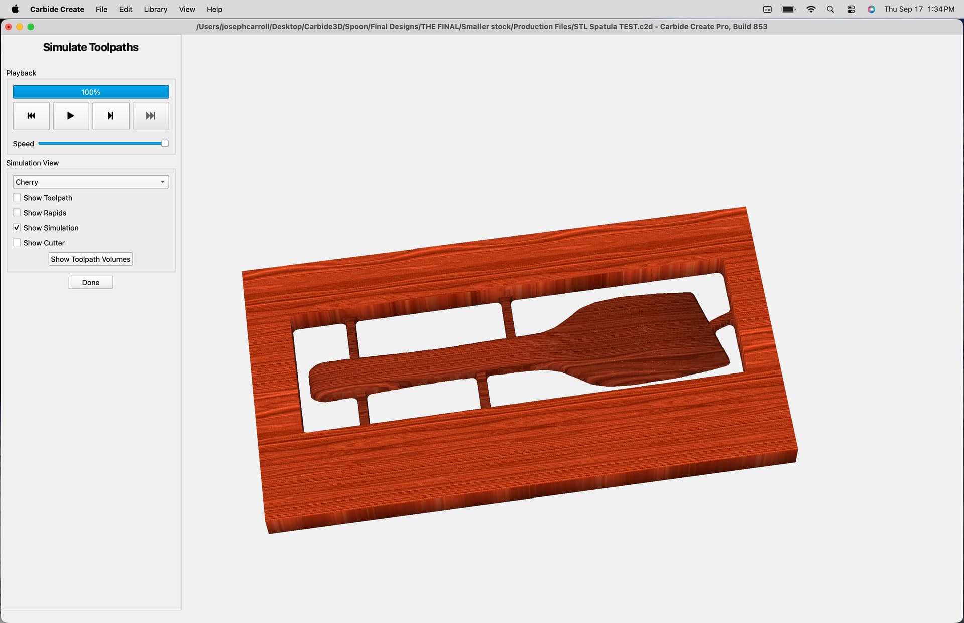
Adding these tabs should help a great deal. Thanks to all. Will report back with result.
A key point I missed at first was to select a merge type of max.
That’s an interesting way to do it Will. For the past two years (since I got my machine), I draw an appropriately-sized square/rectangle/circle to somewhat match the shape of the STL object, then delete the square and redraw a shape around the STL using polylines. This technique minimizes the amount of carving (especially if there are large “dead” areas. Drawing the polylines and making sure that they’re close enough for tabs to work in the simulation may only take 5-10 minutes on the computer.
@joeysawdust I’m also playing around with something like this leaving 1/16" for the base. We will see as I haven’t machined any of this yet. Just playing with the models.
Solid feedback Will, well played.
Thanks Will. I did figure that out after my original post.