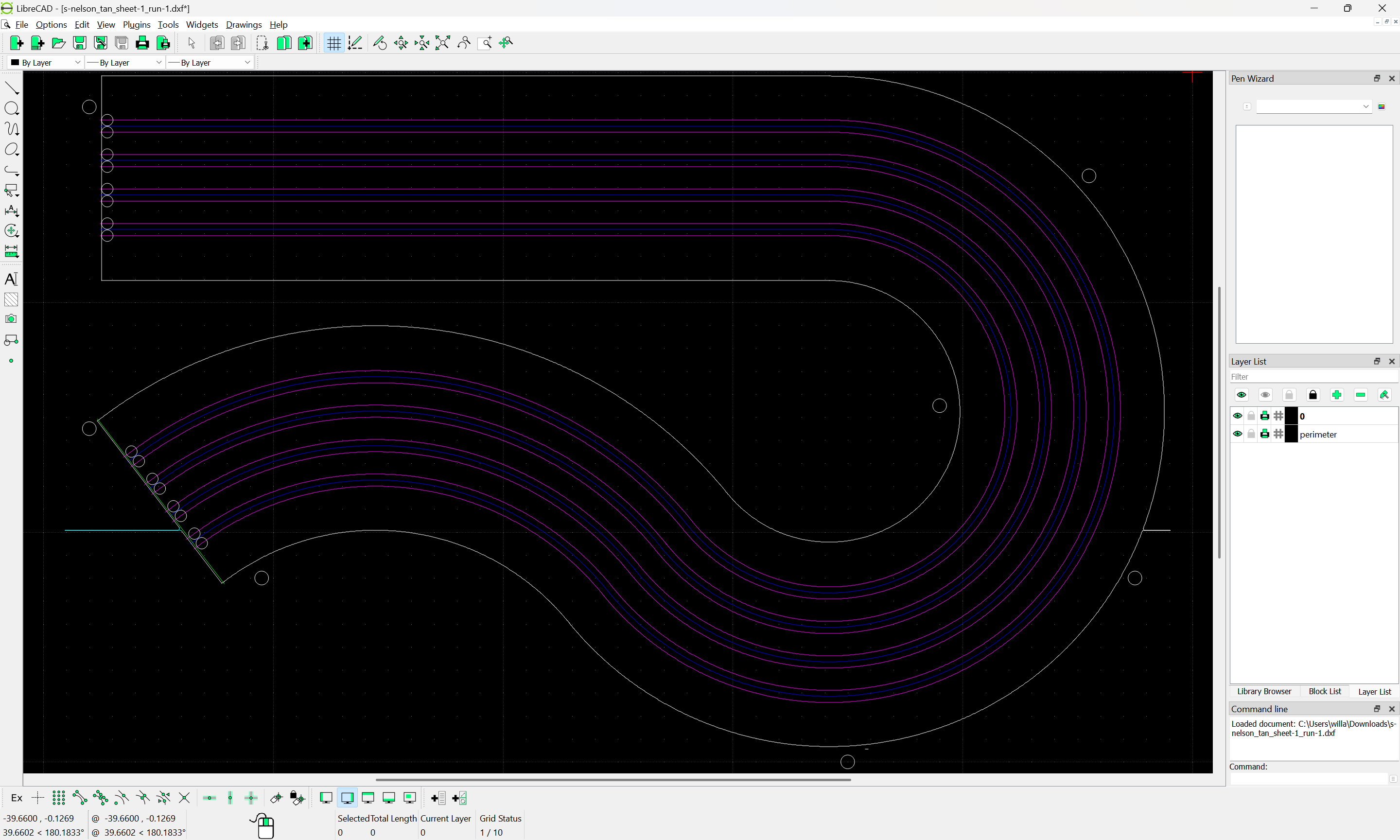
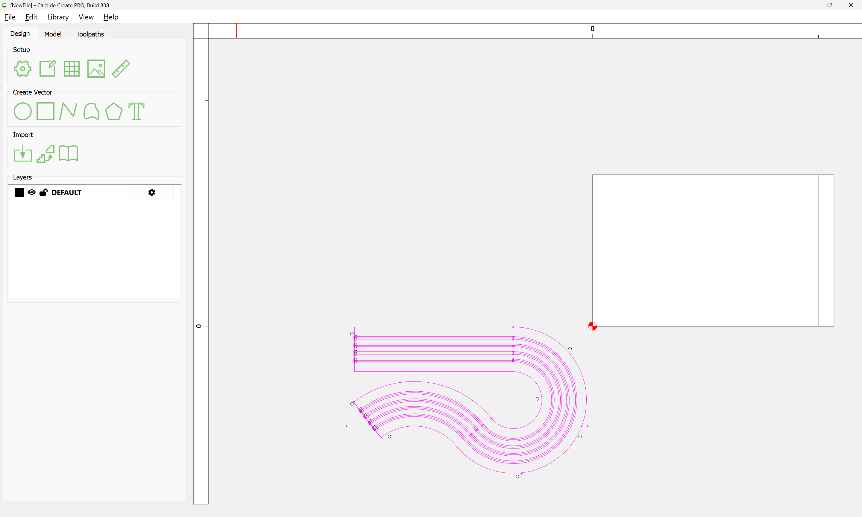
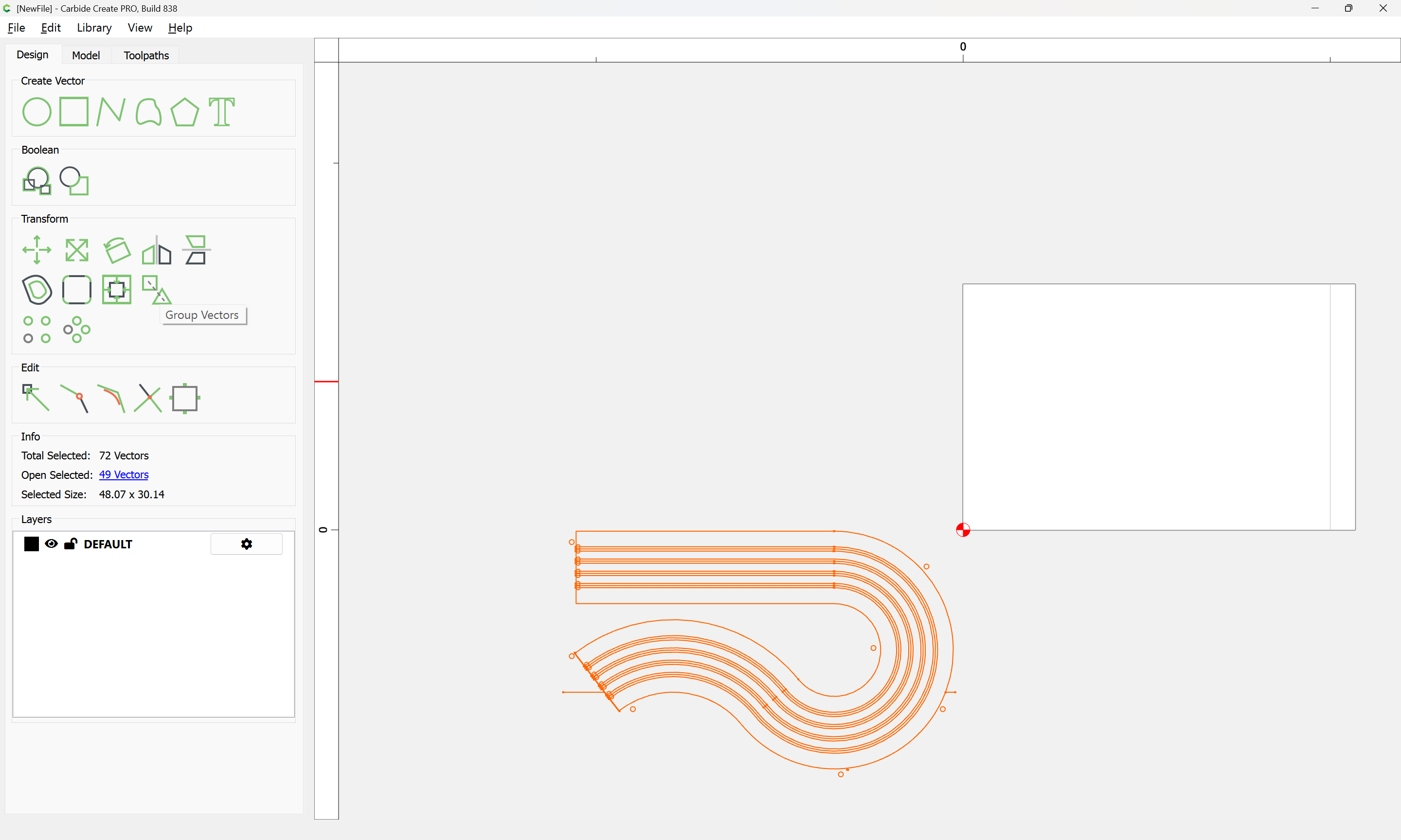
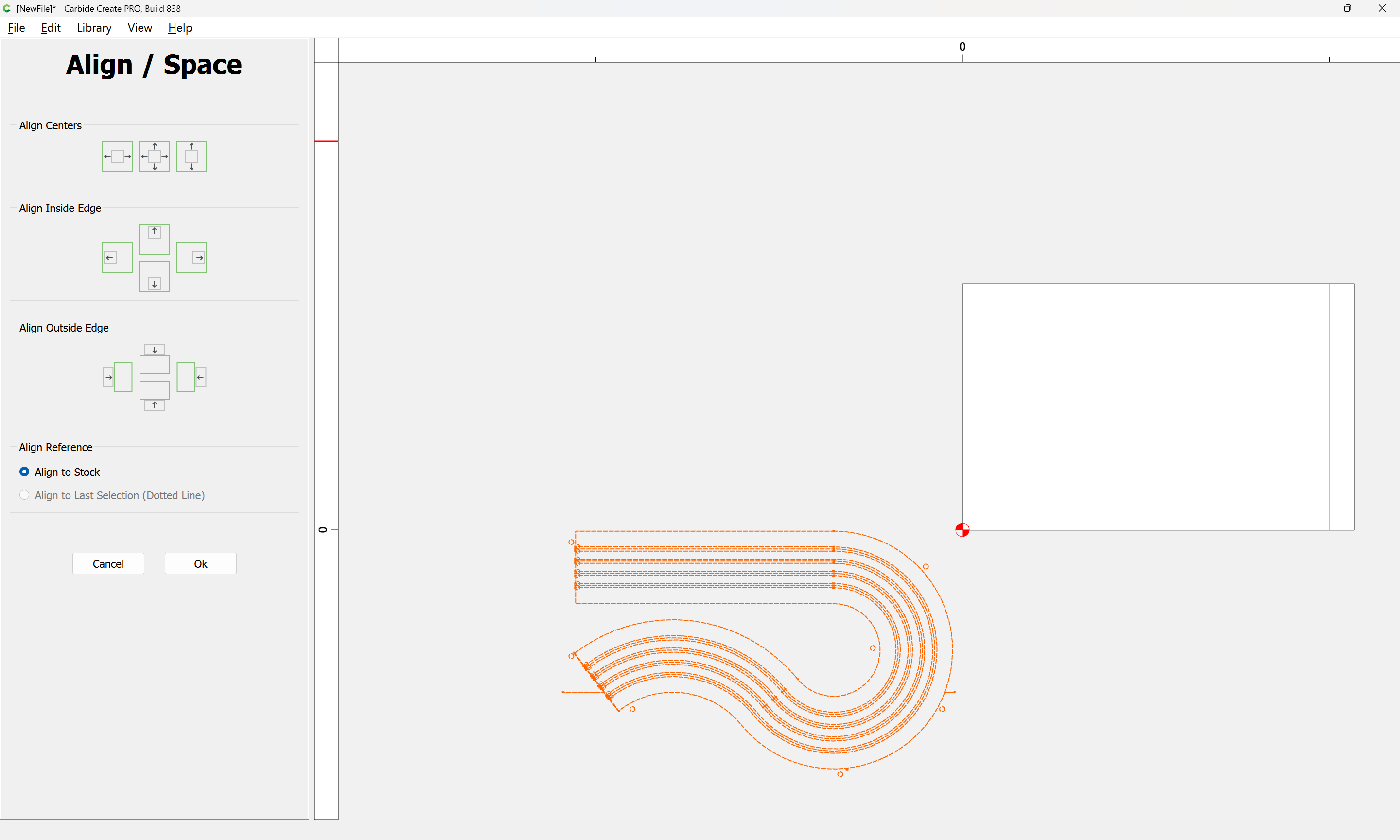
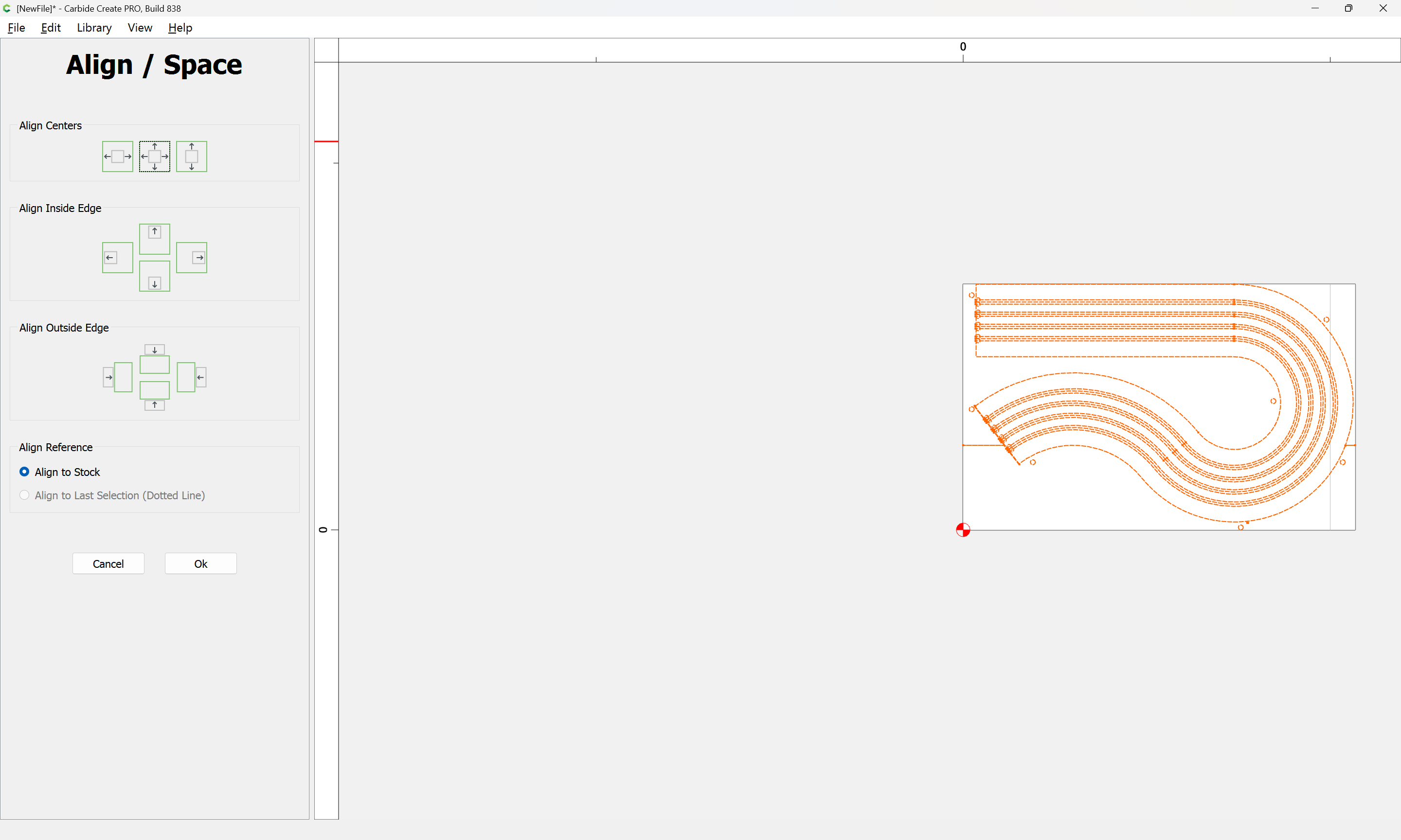
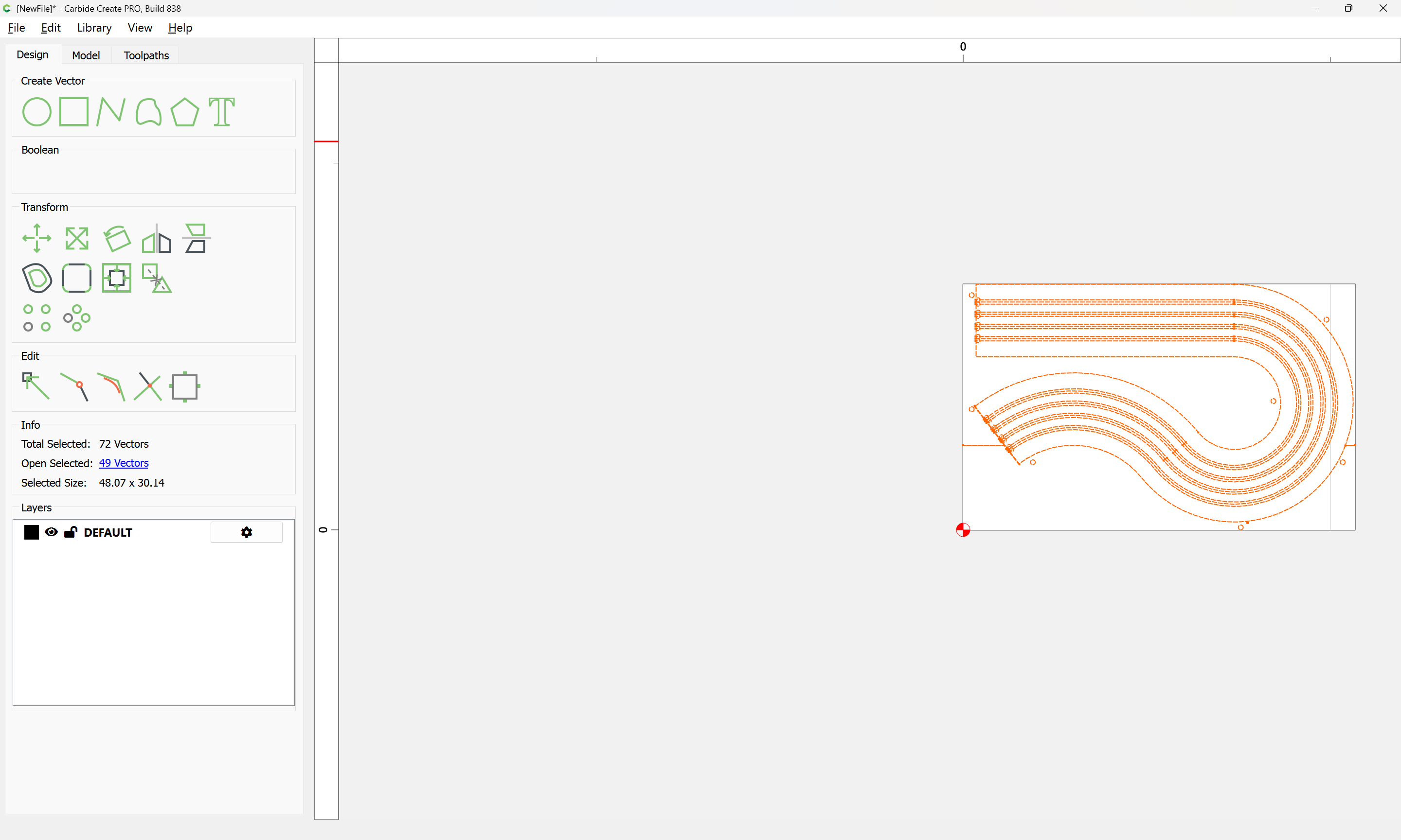
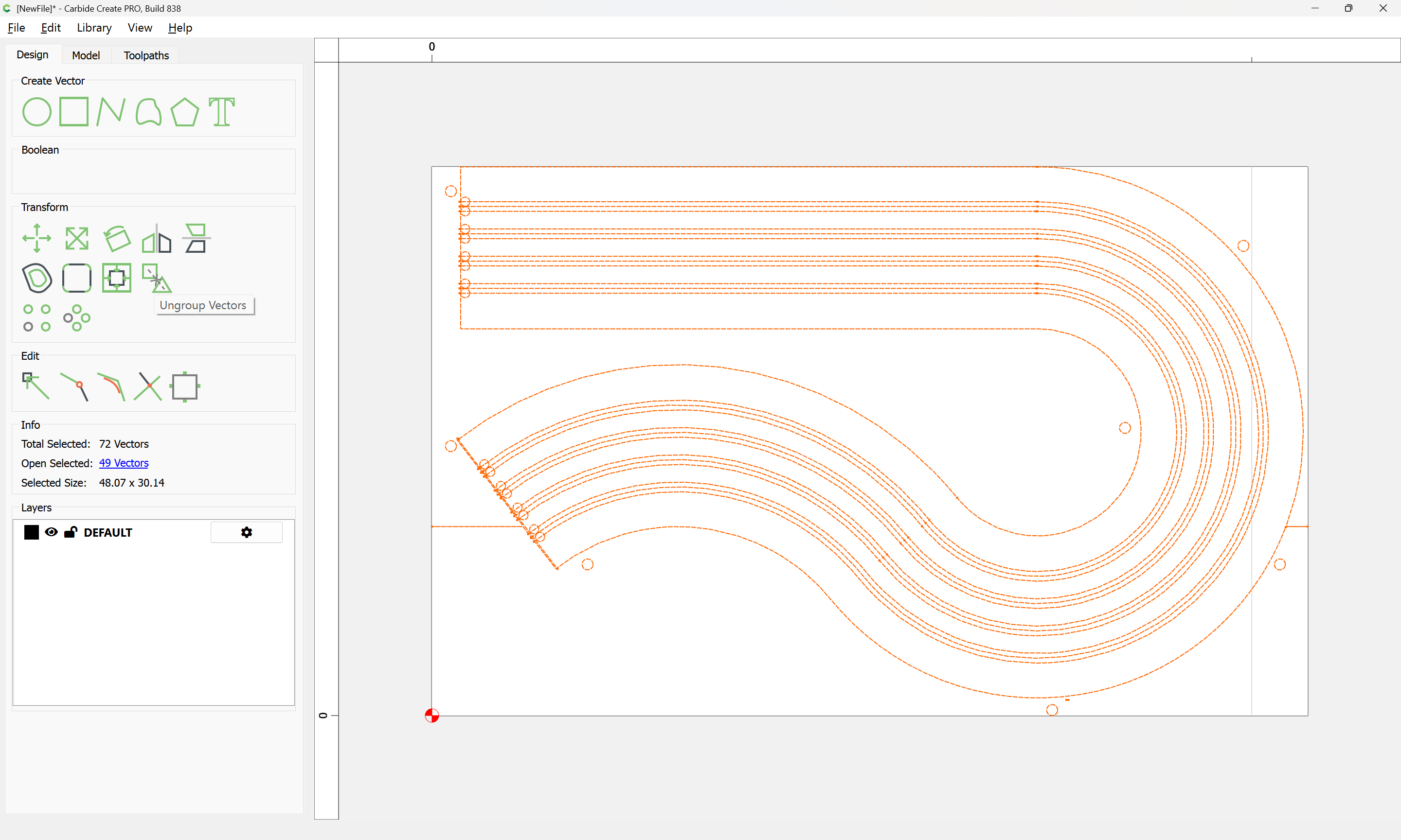
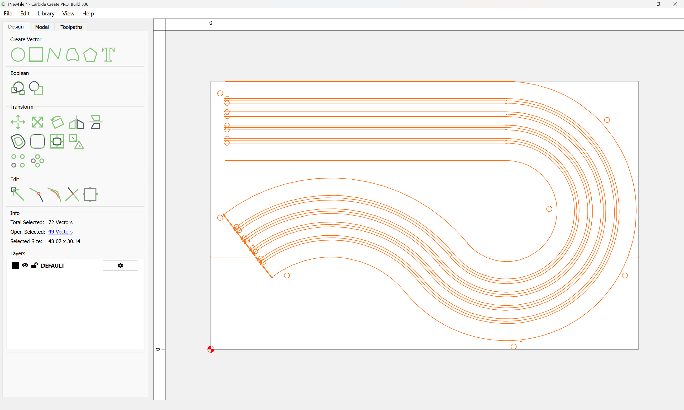
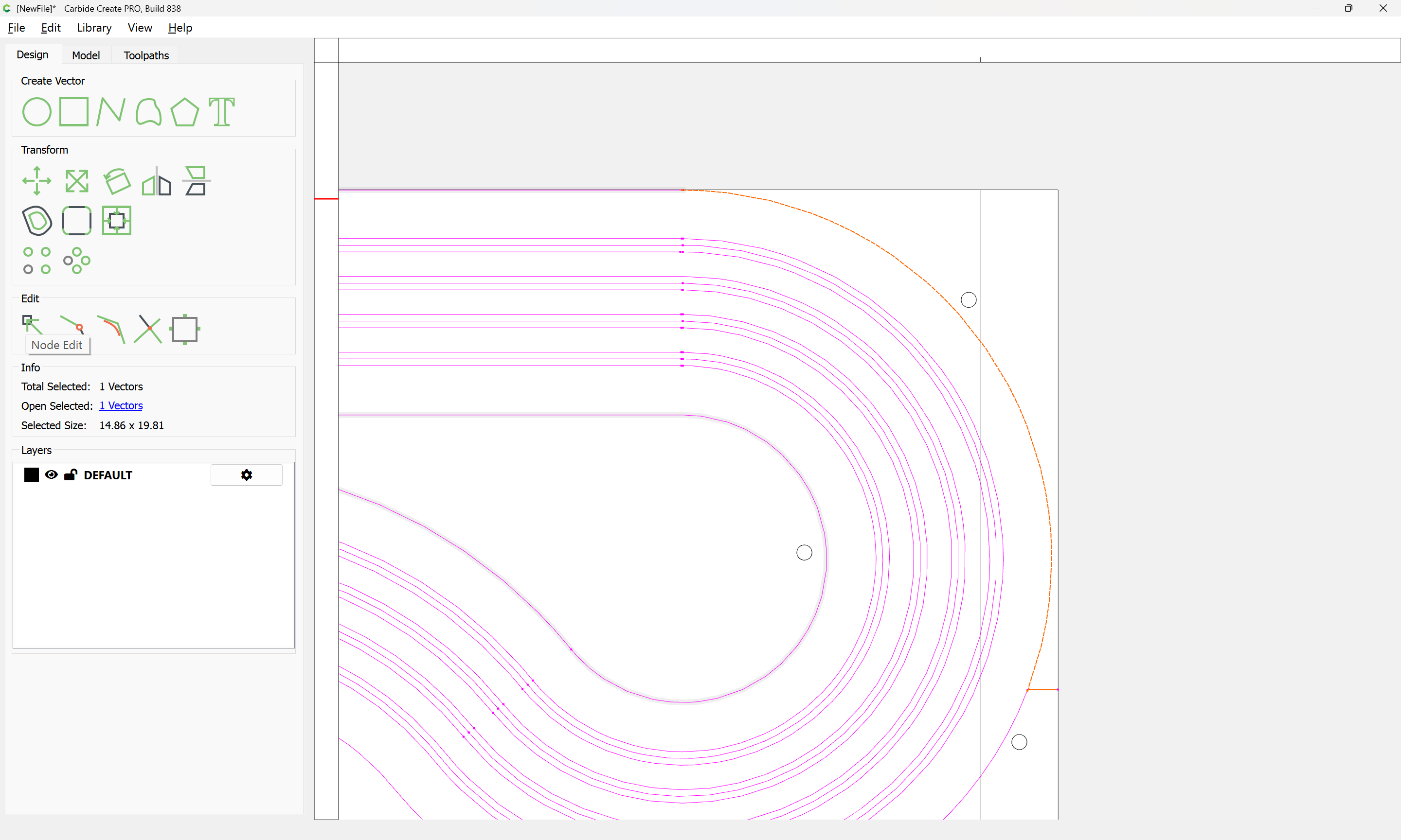
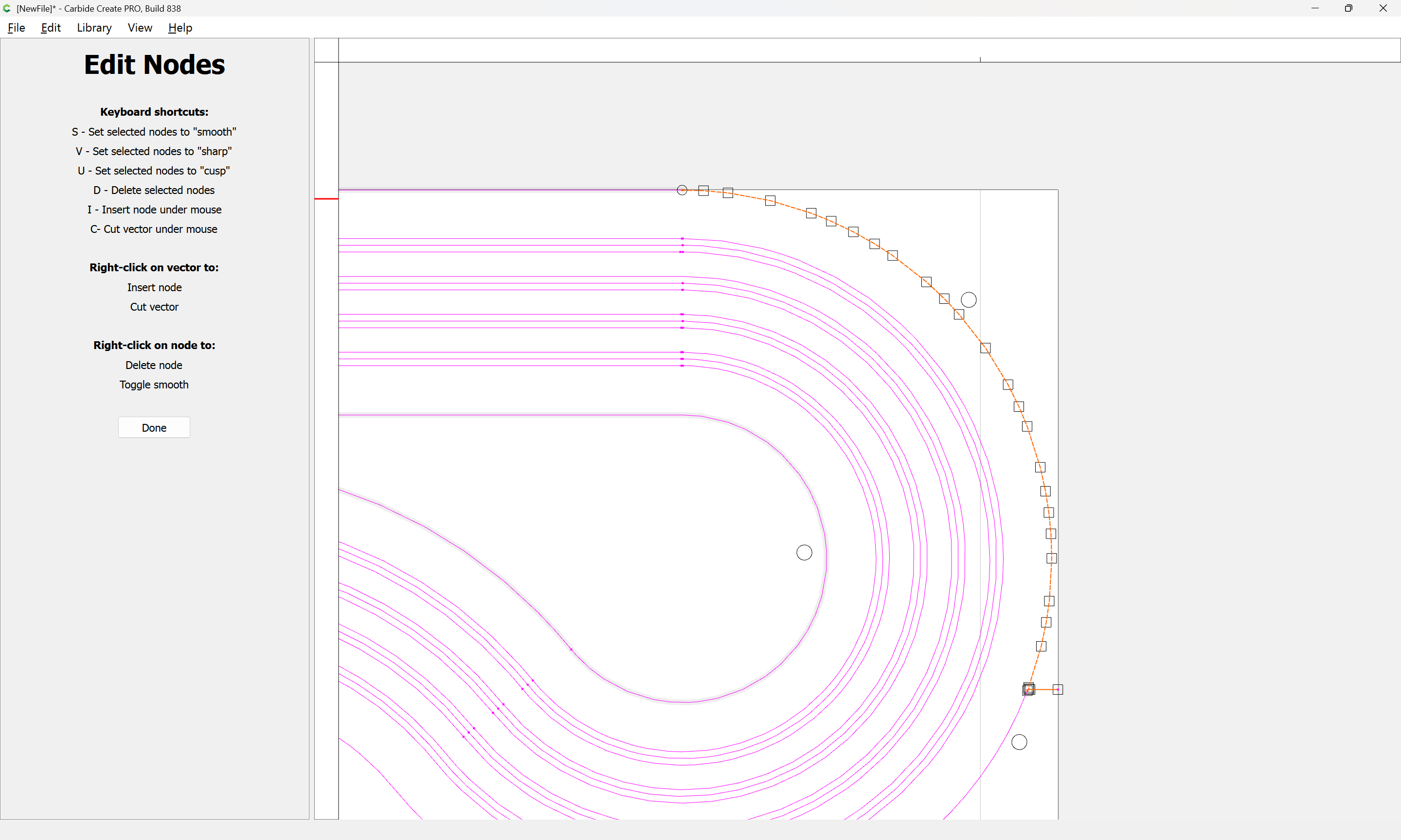
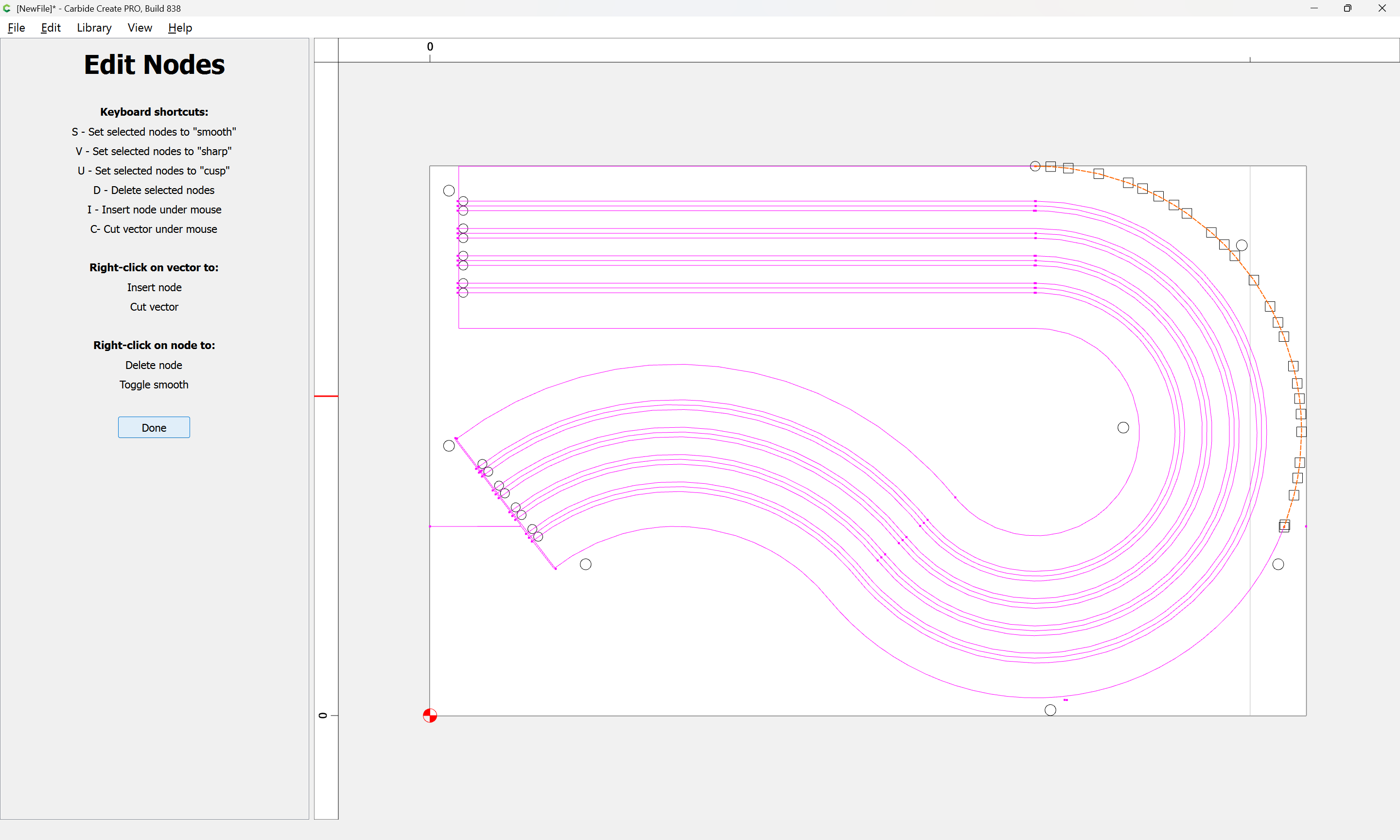
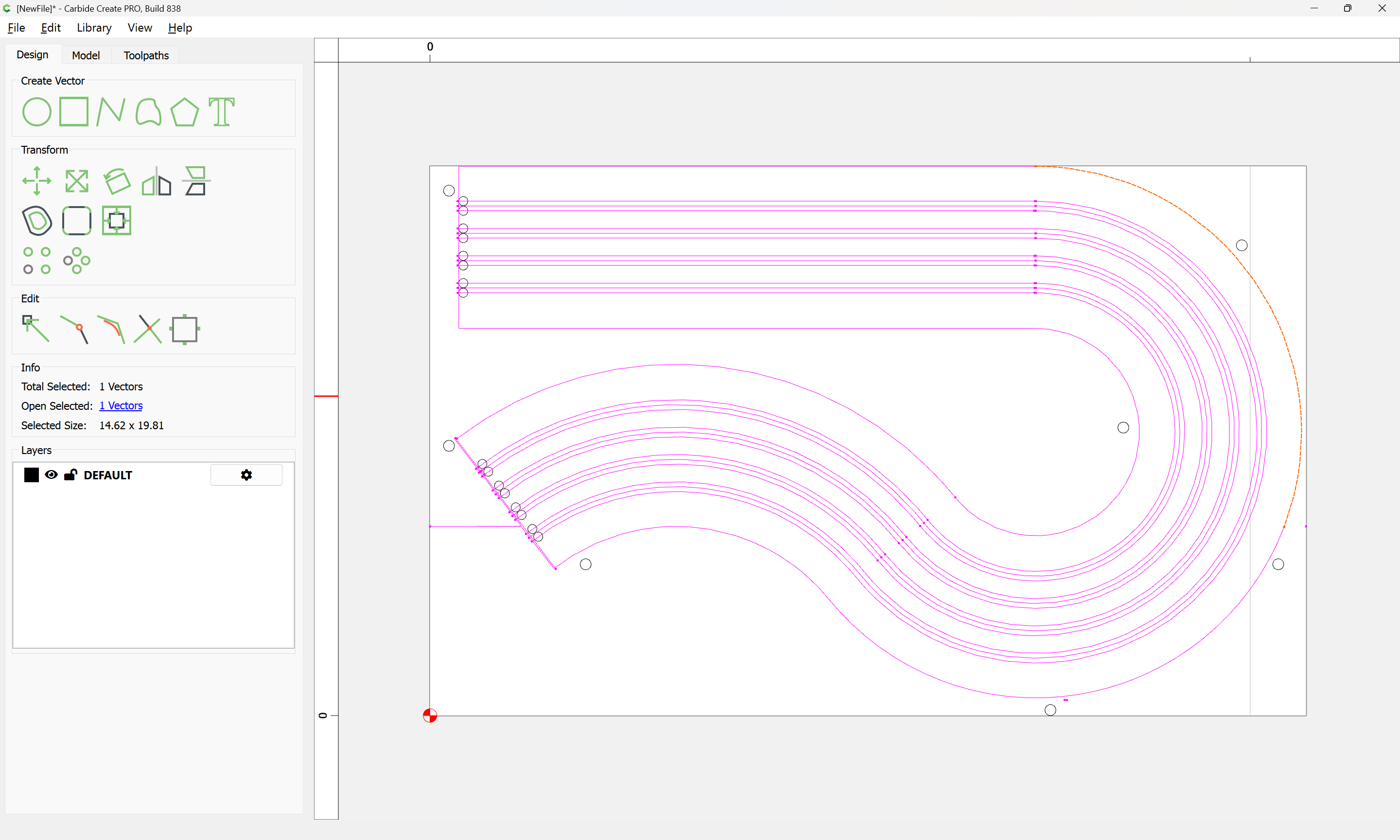
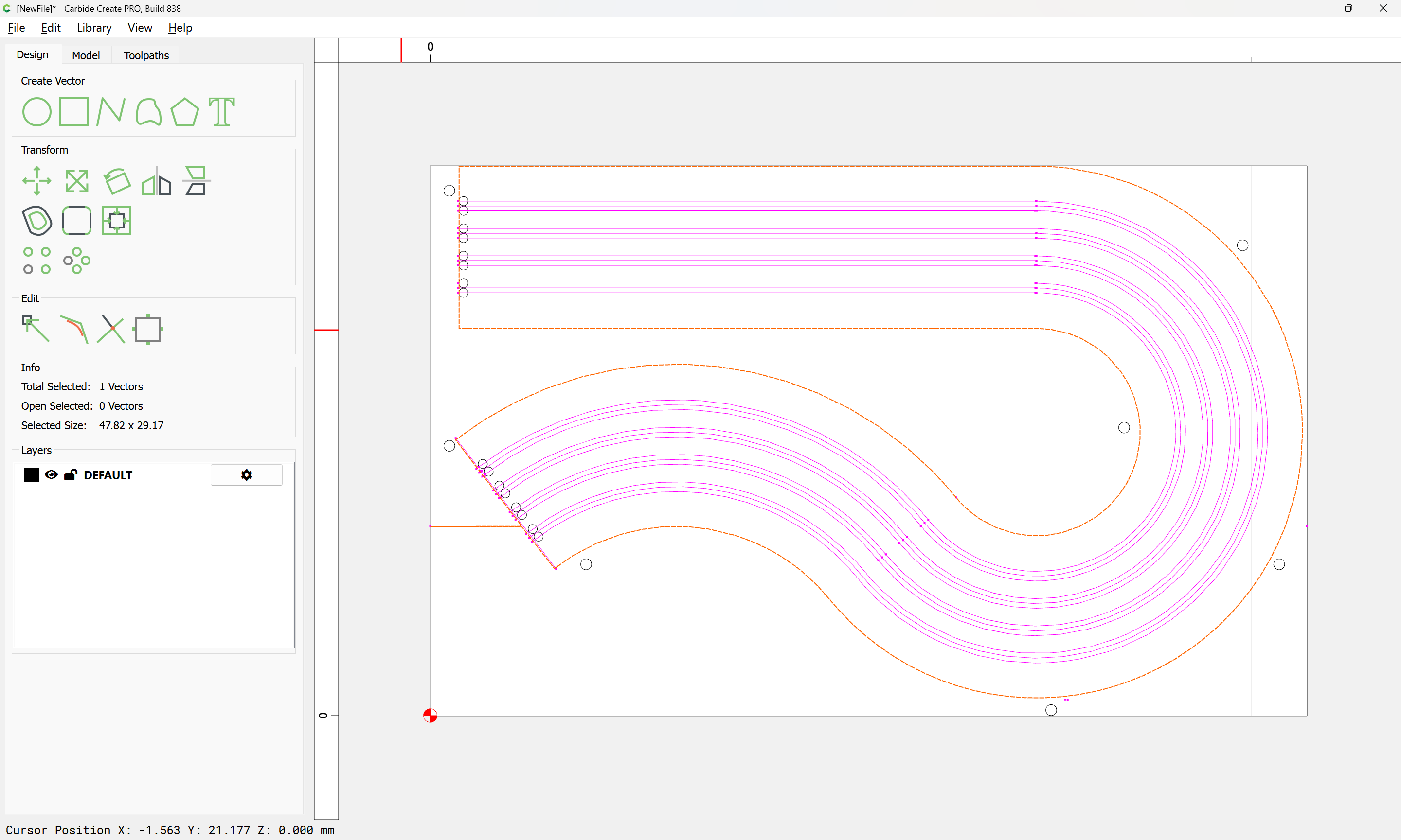
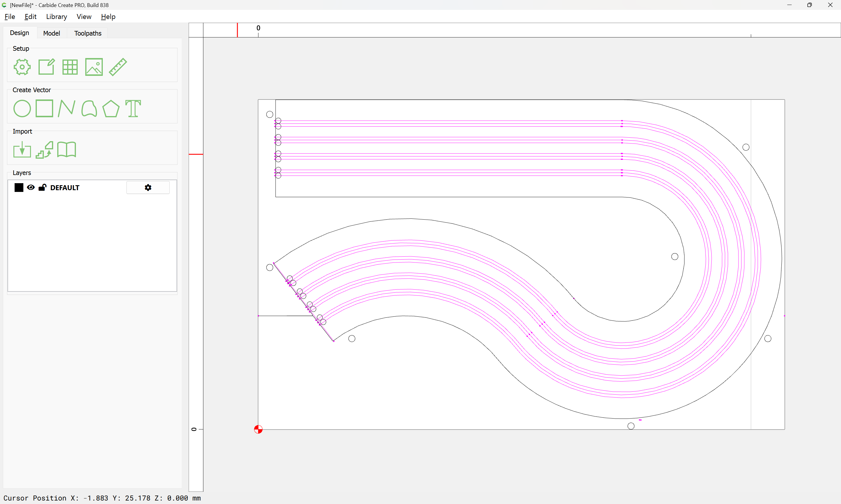
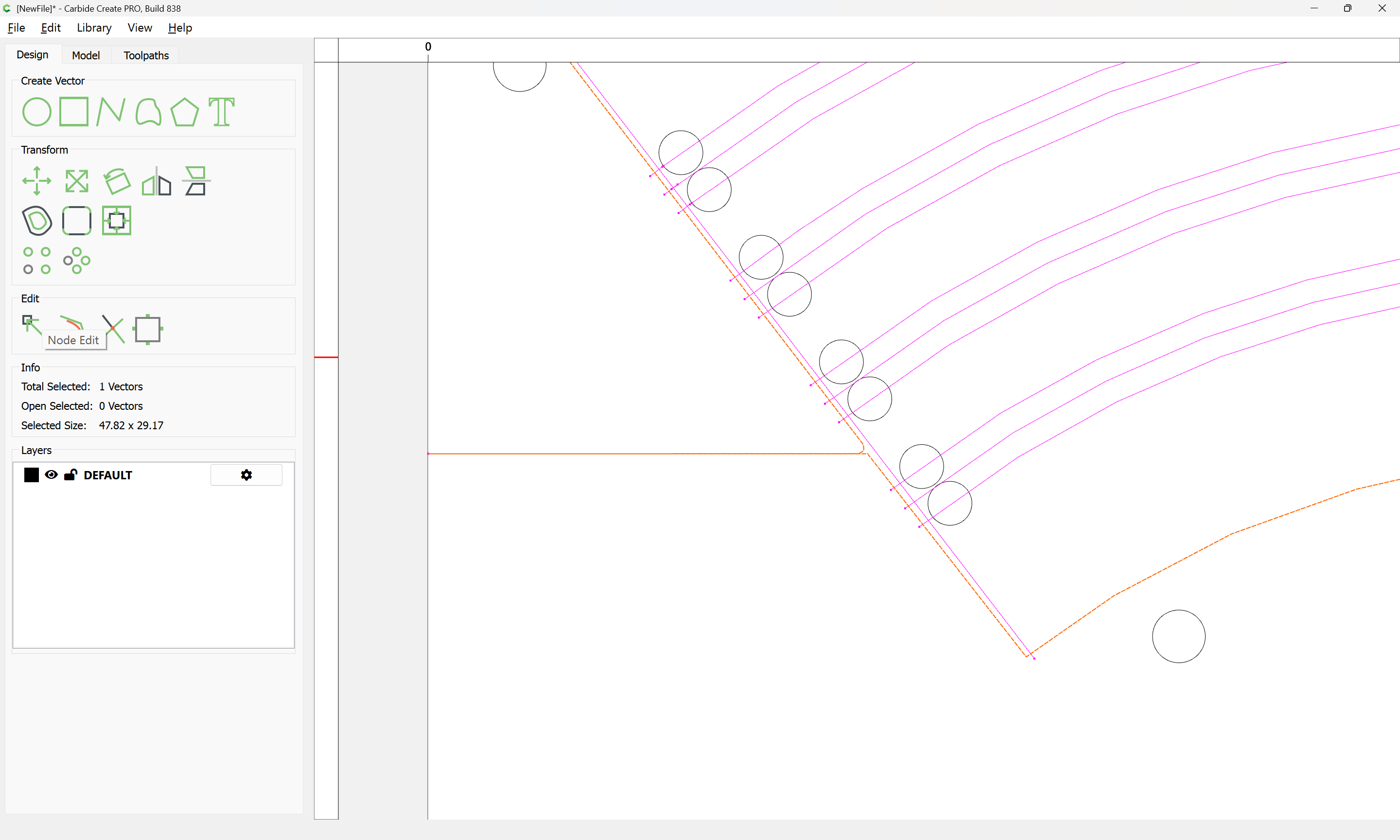
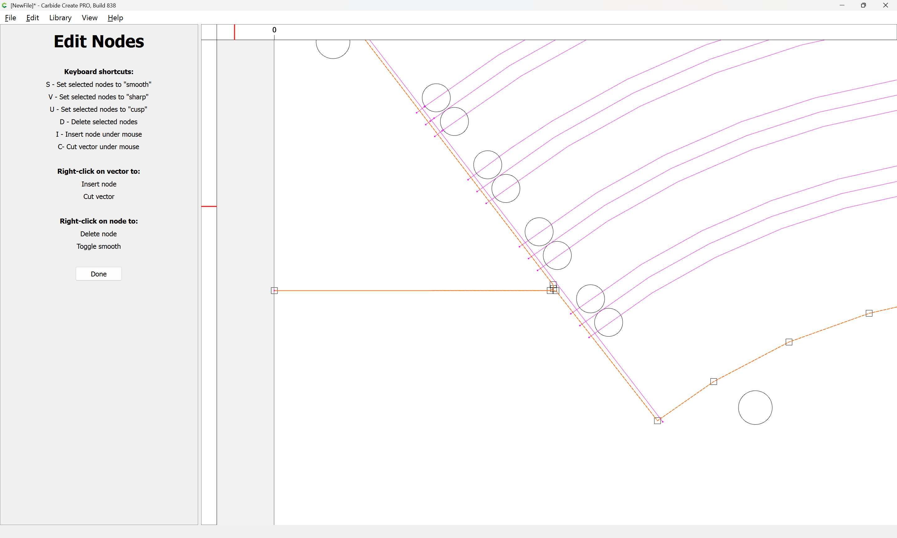
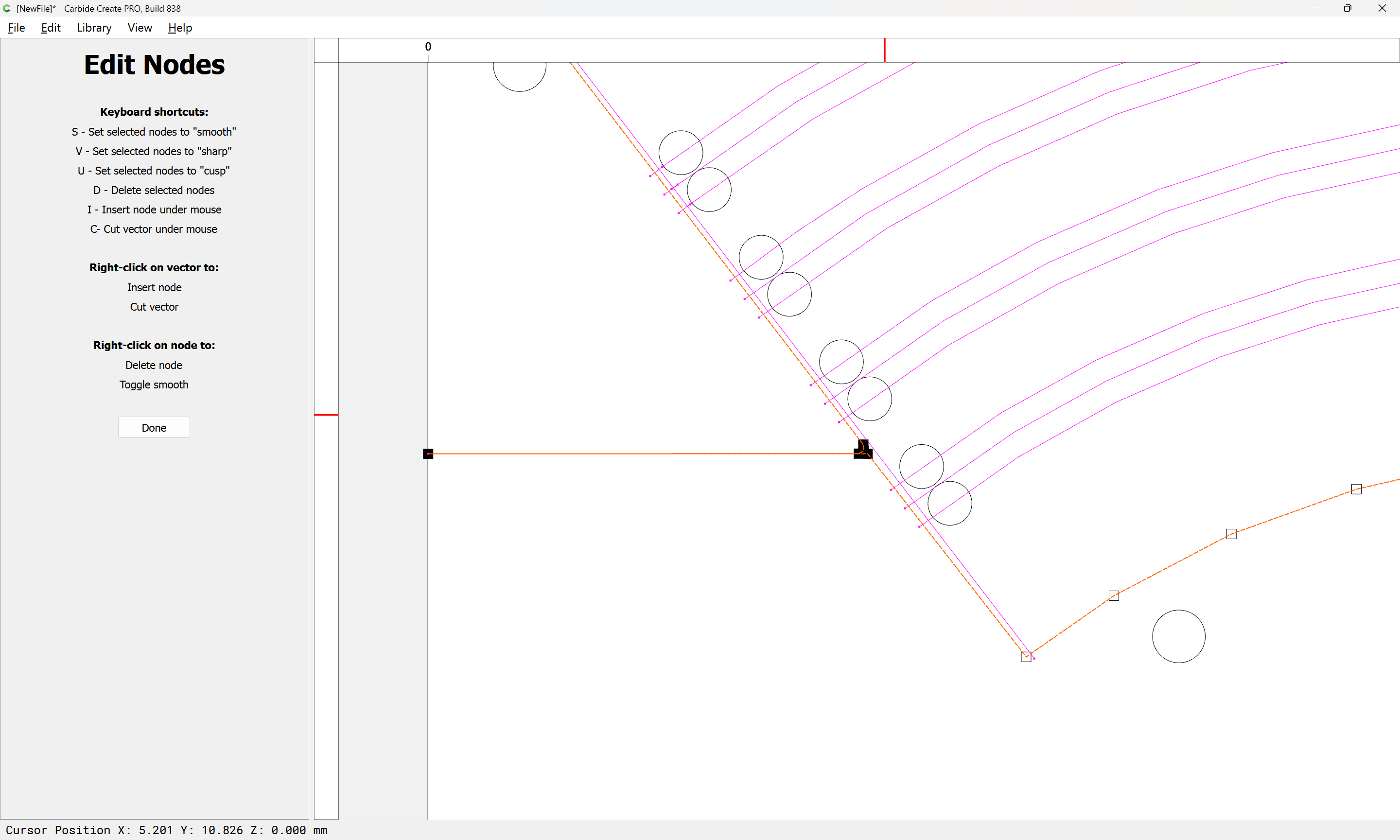
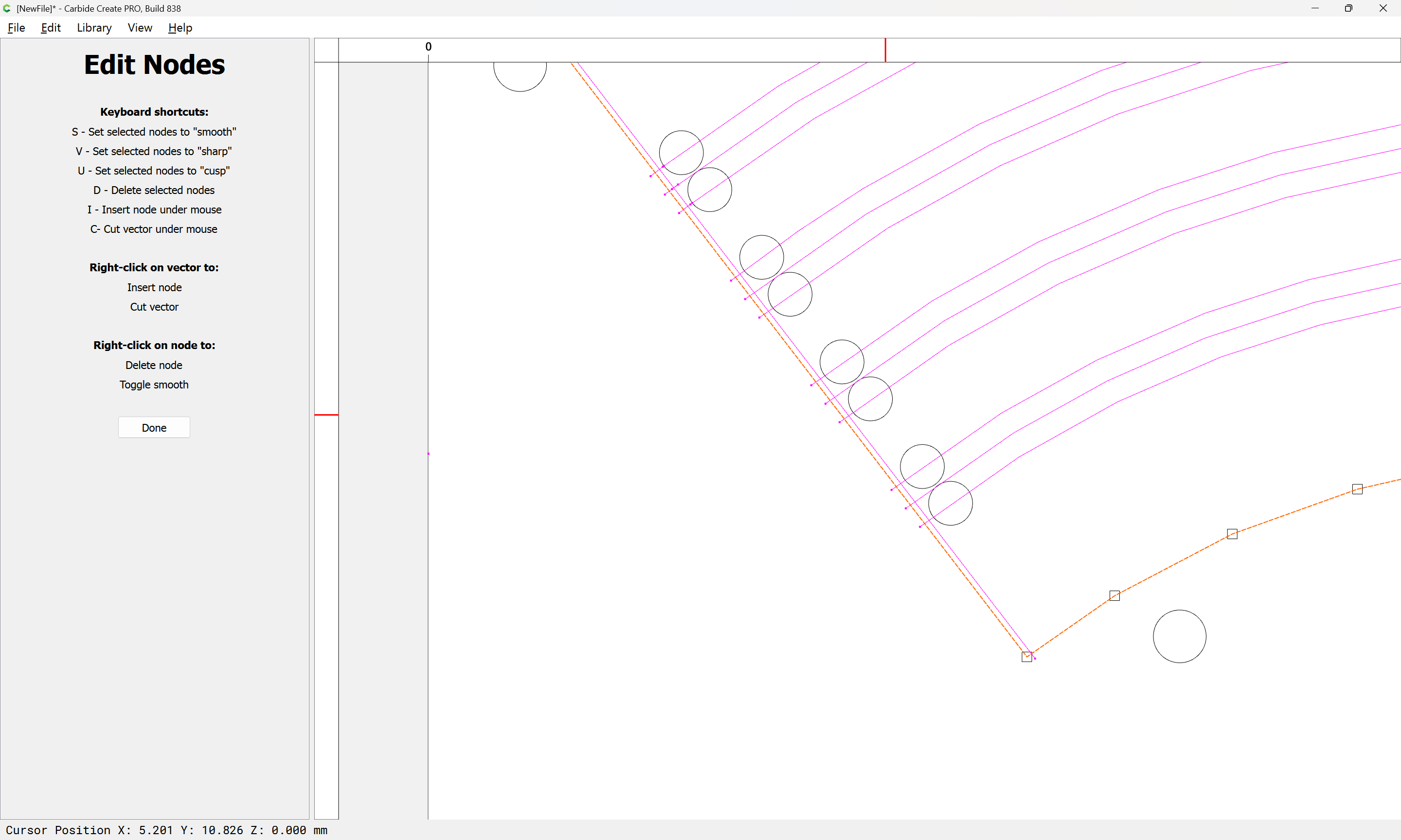
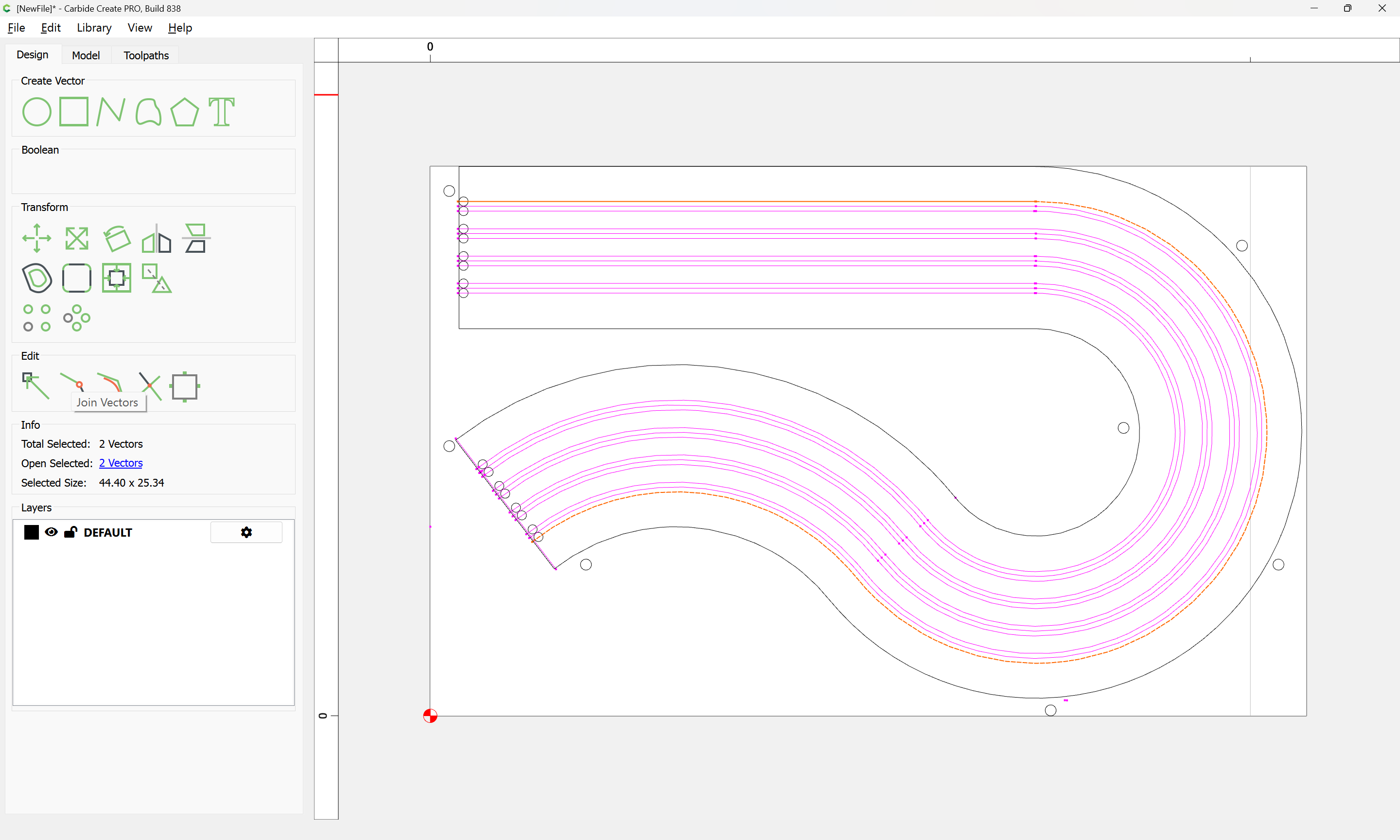
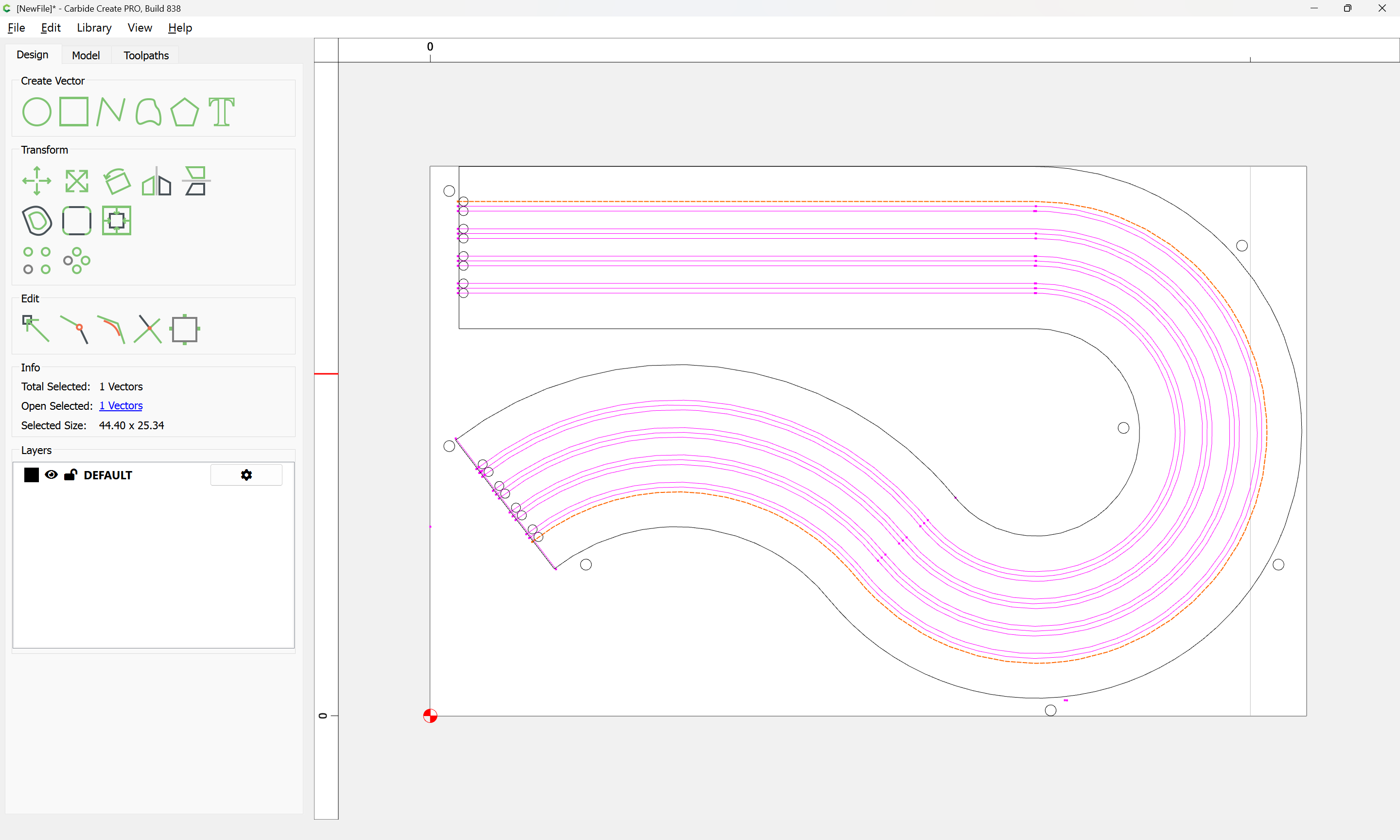
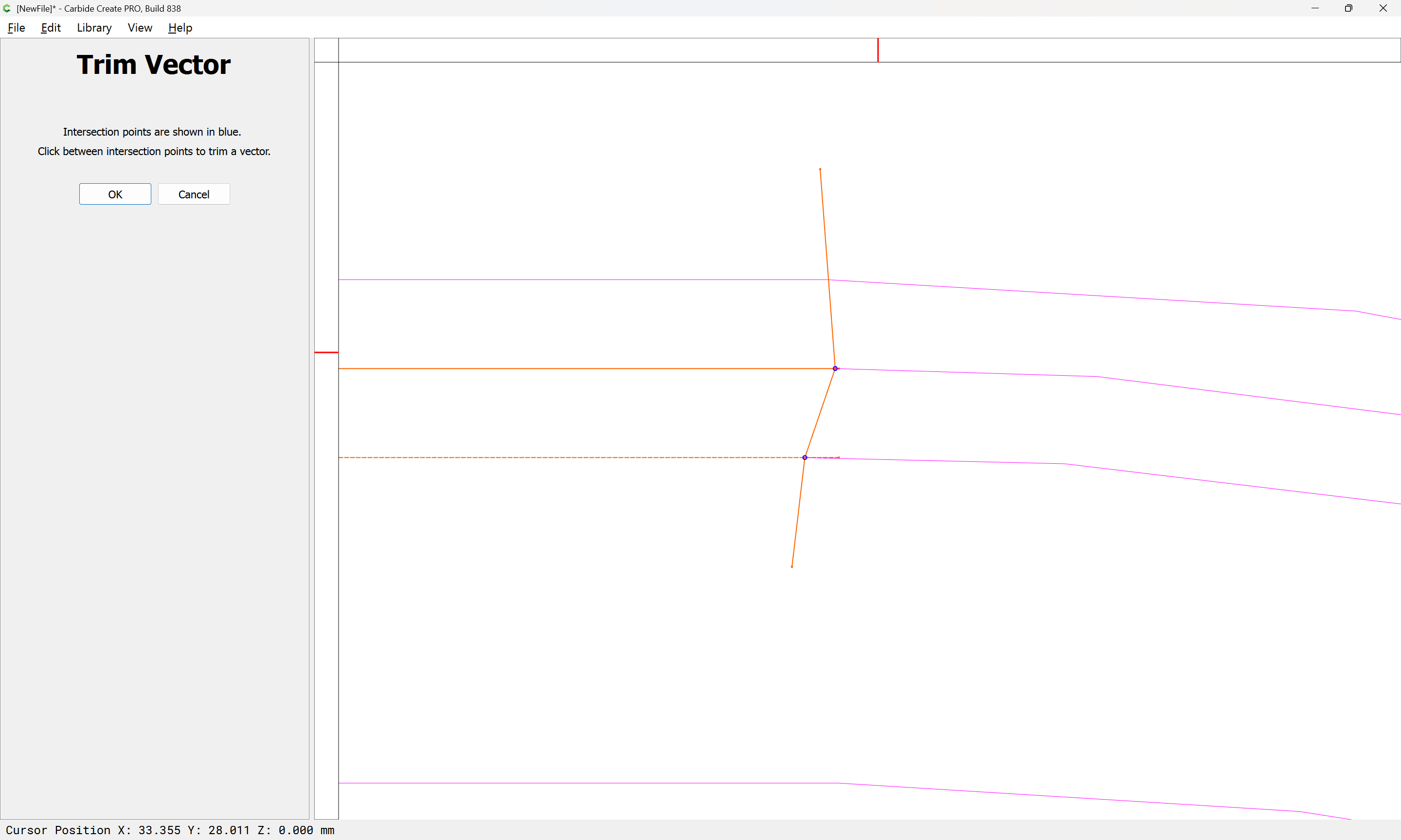
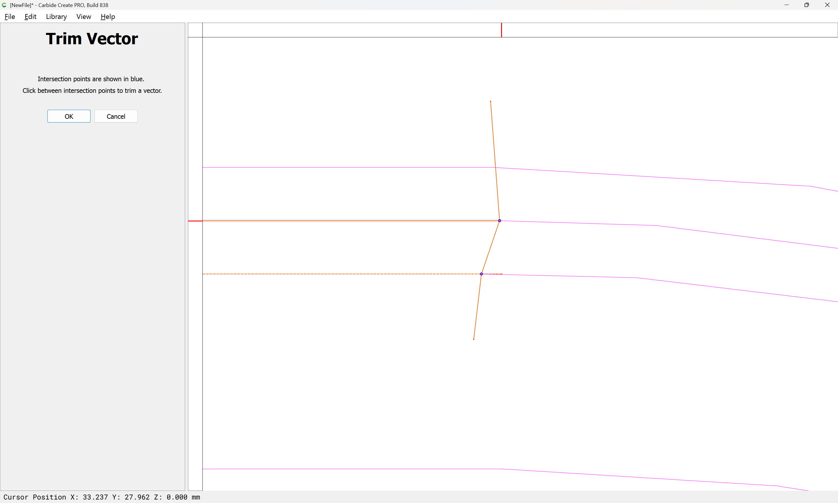
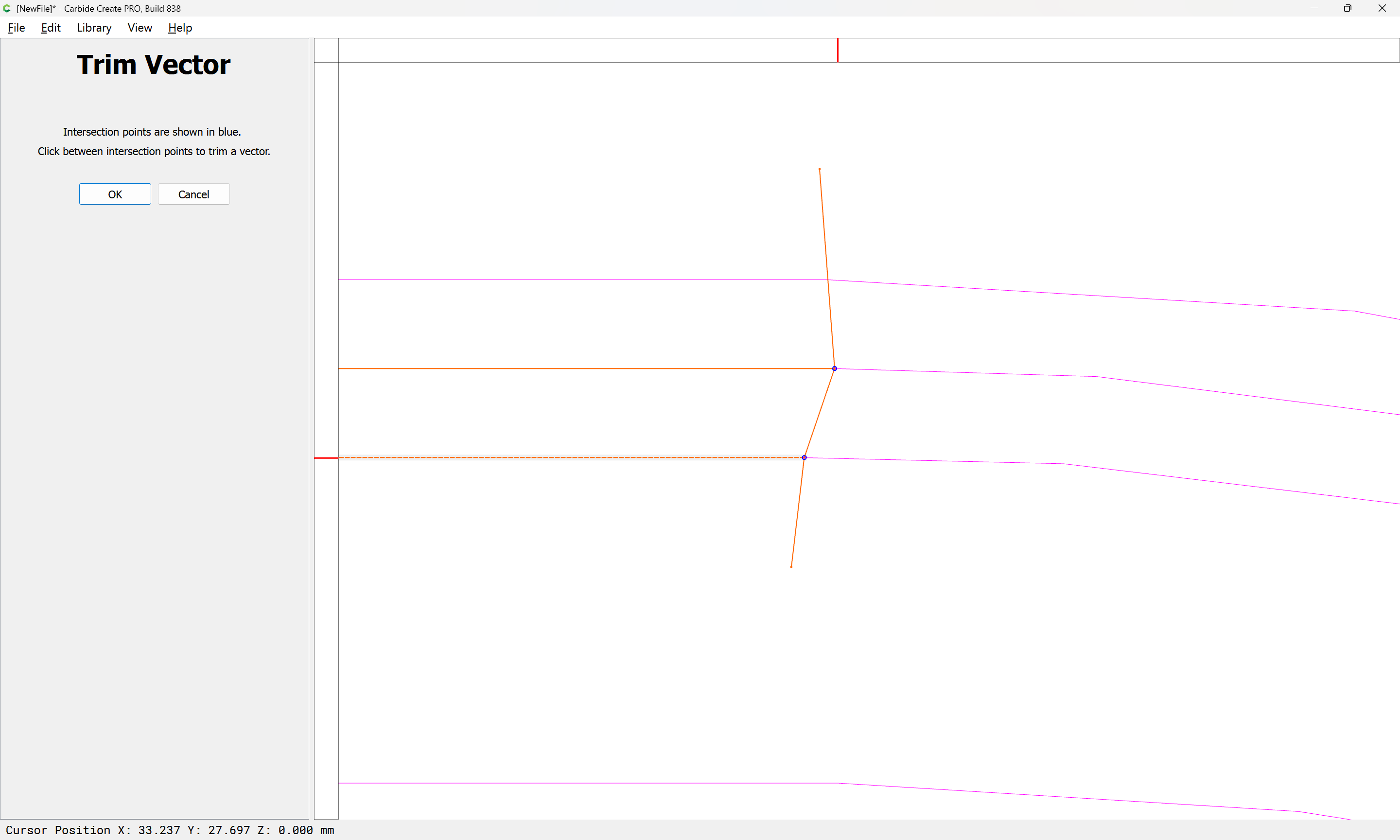
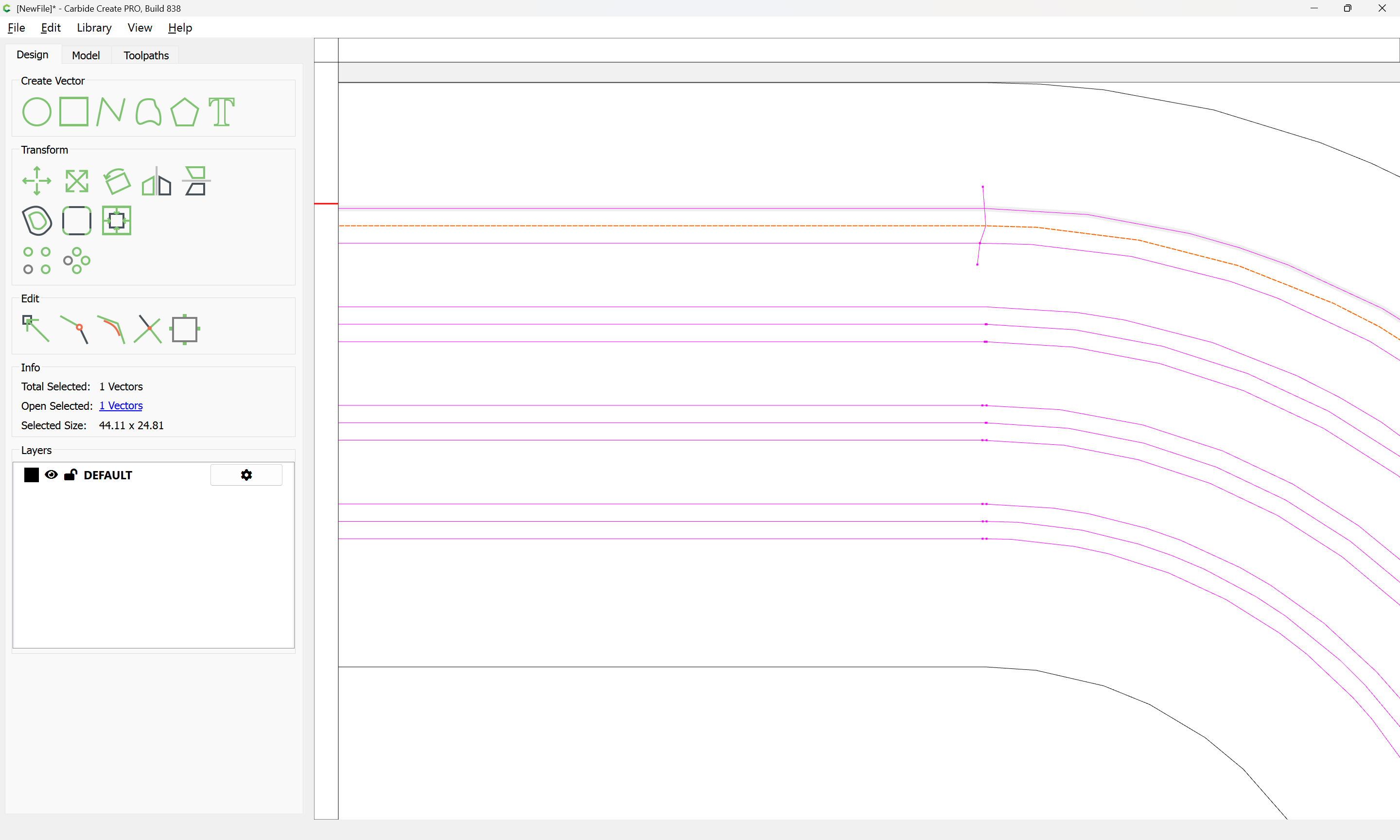
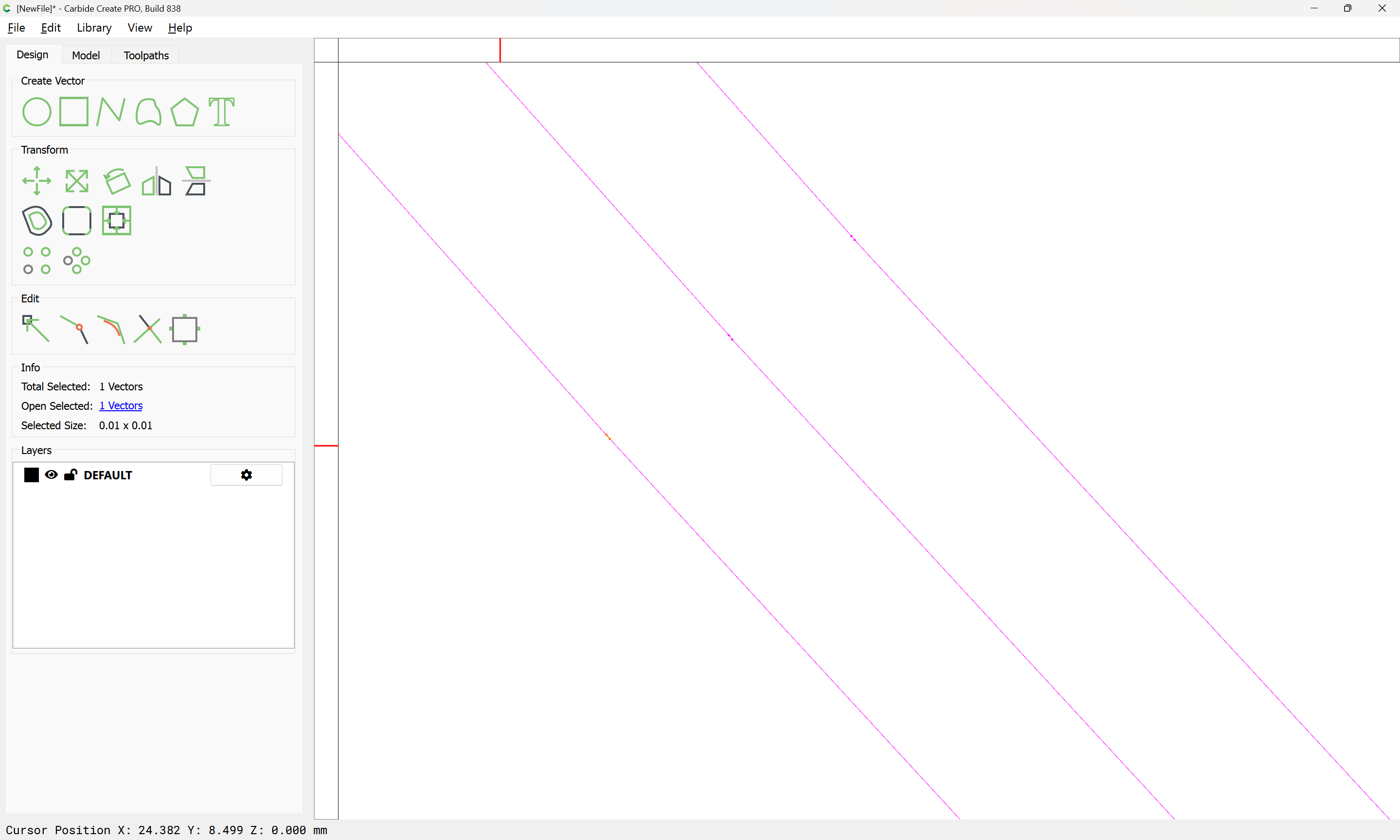
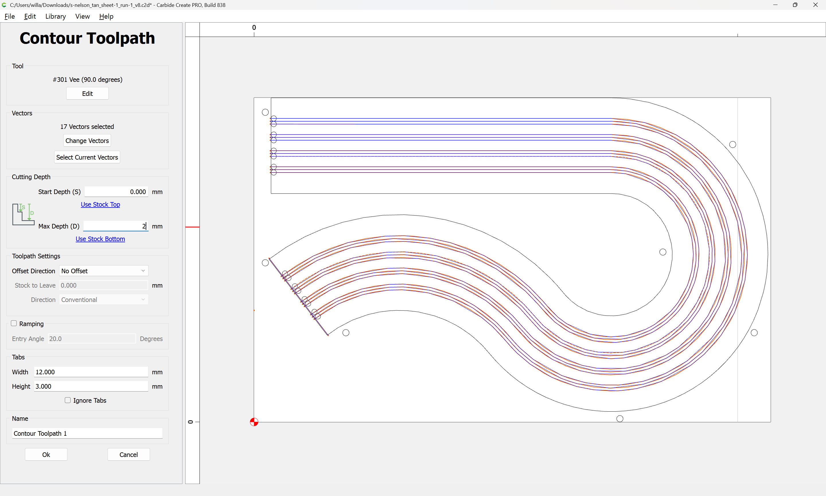
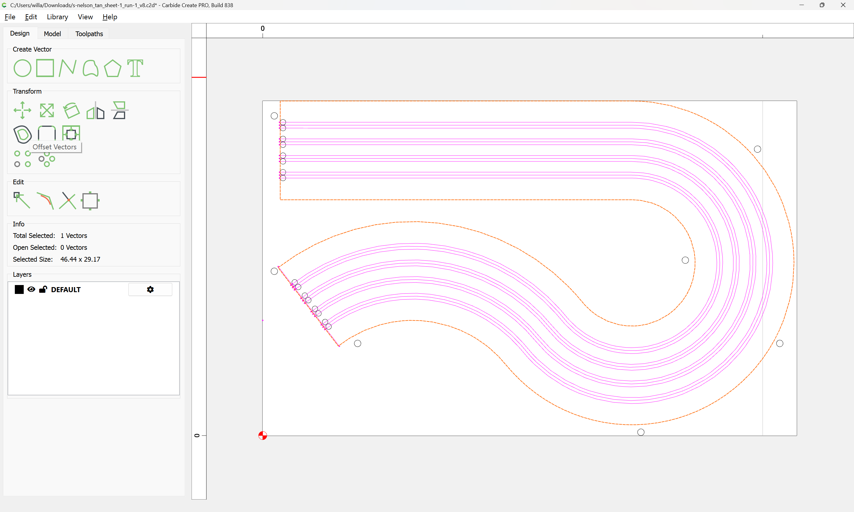
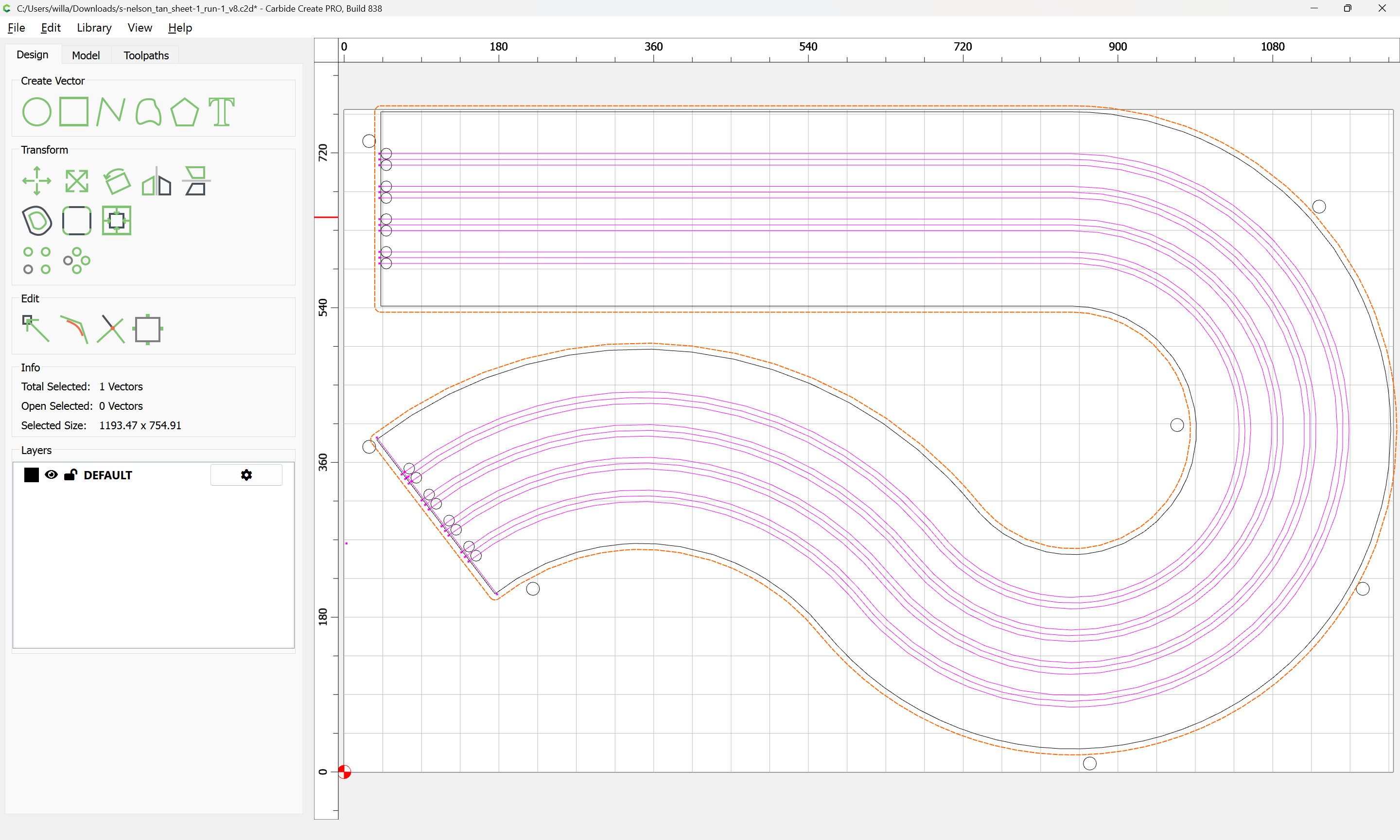
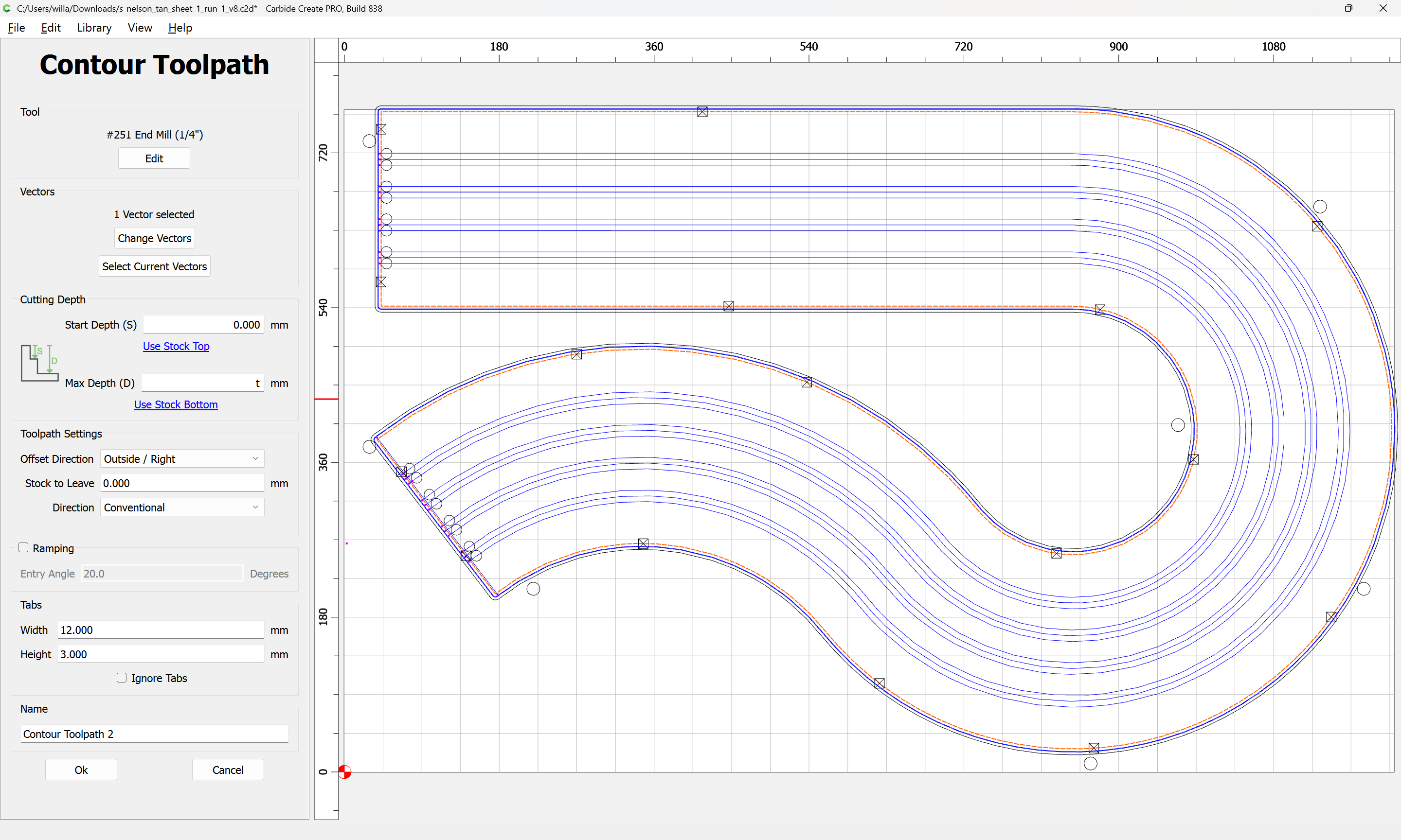
I drew perimeter cut as the toolpath only. And It still isn’t one loop in Carbide.
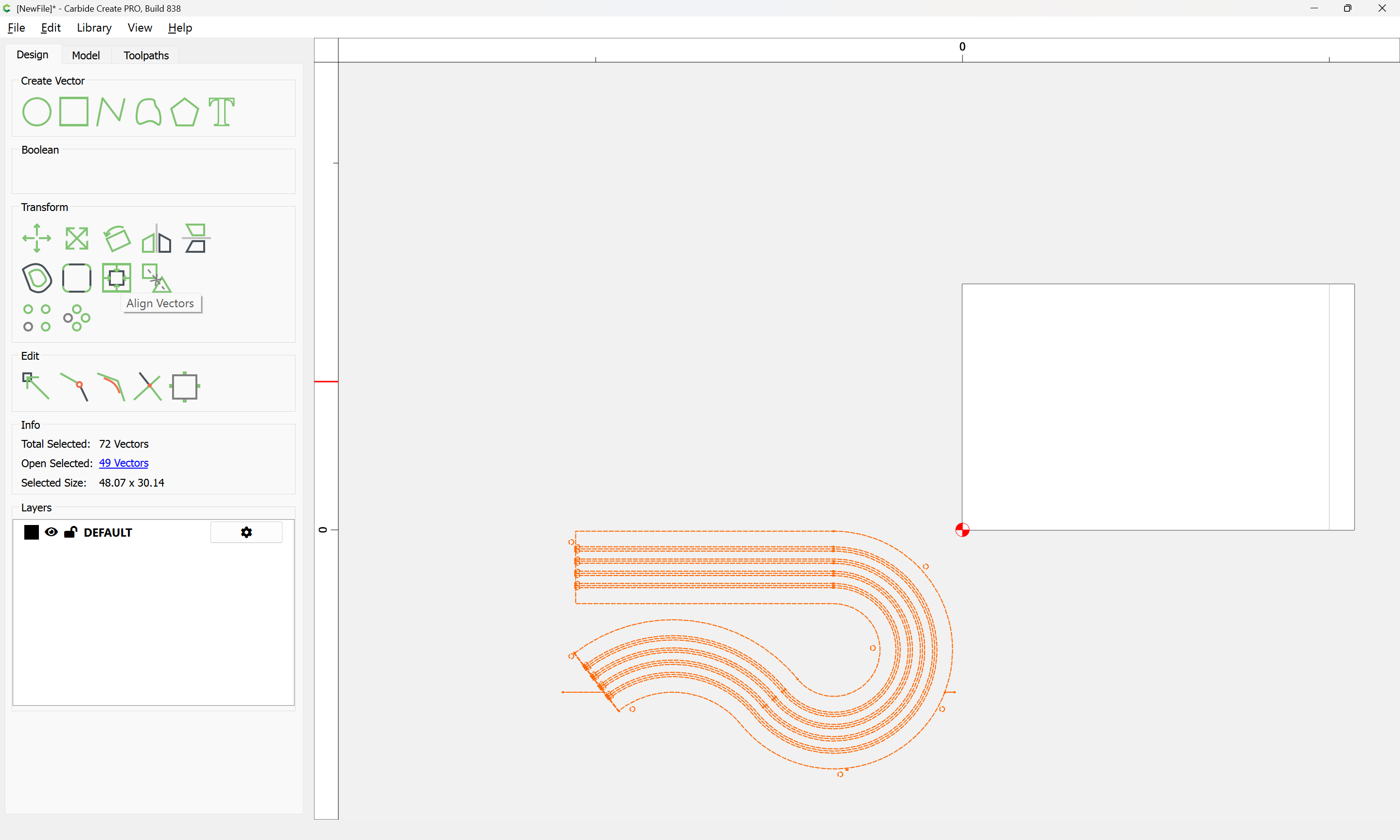
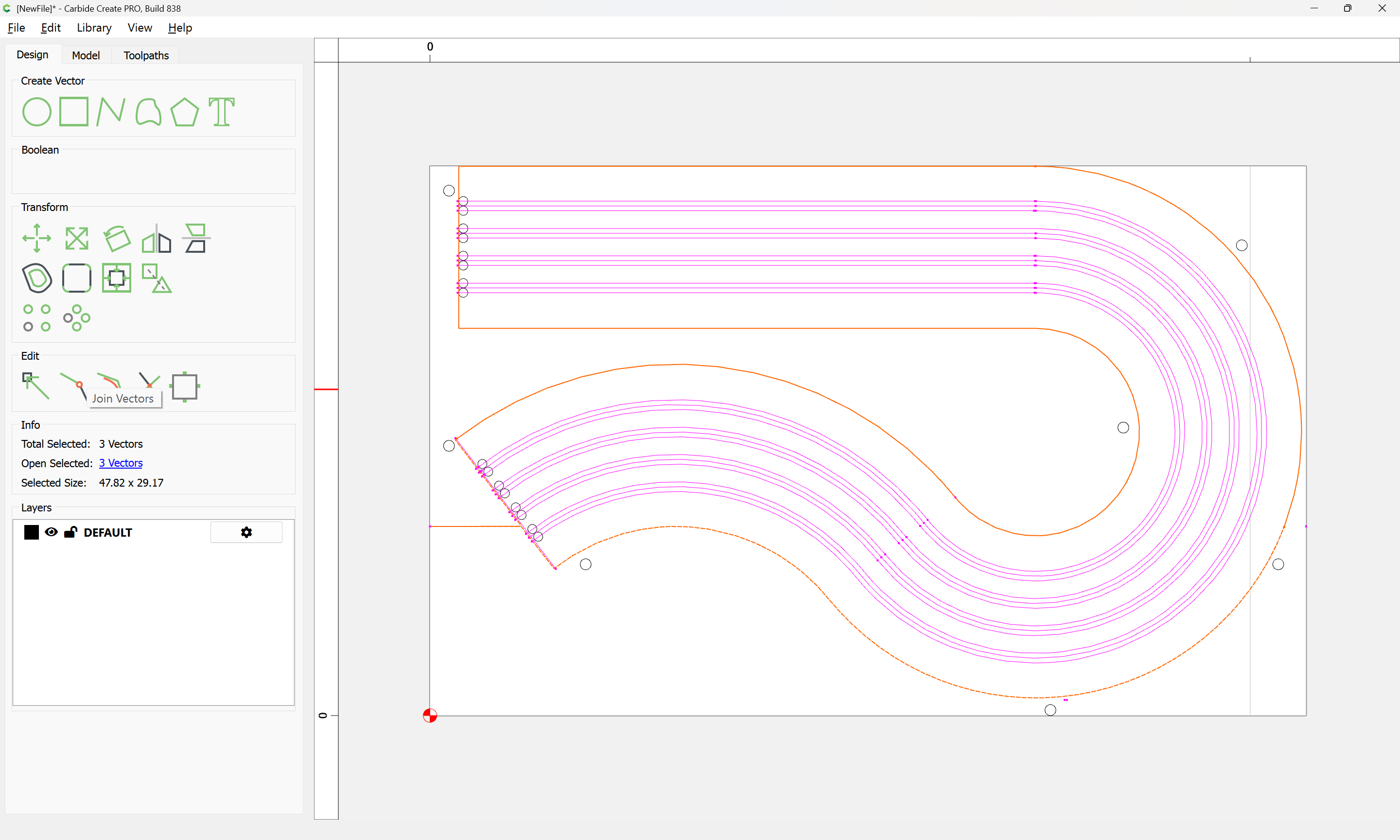
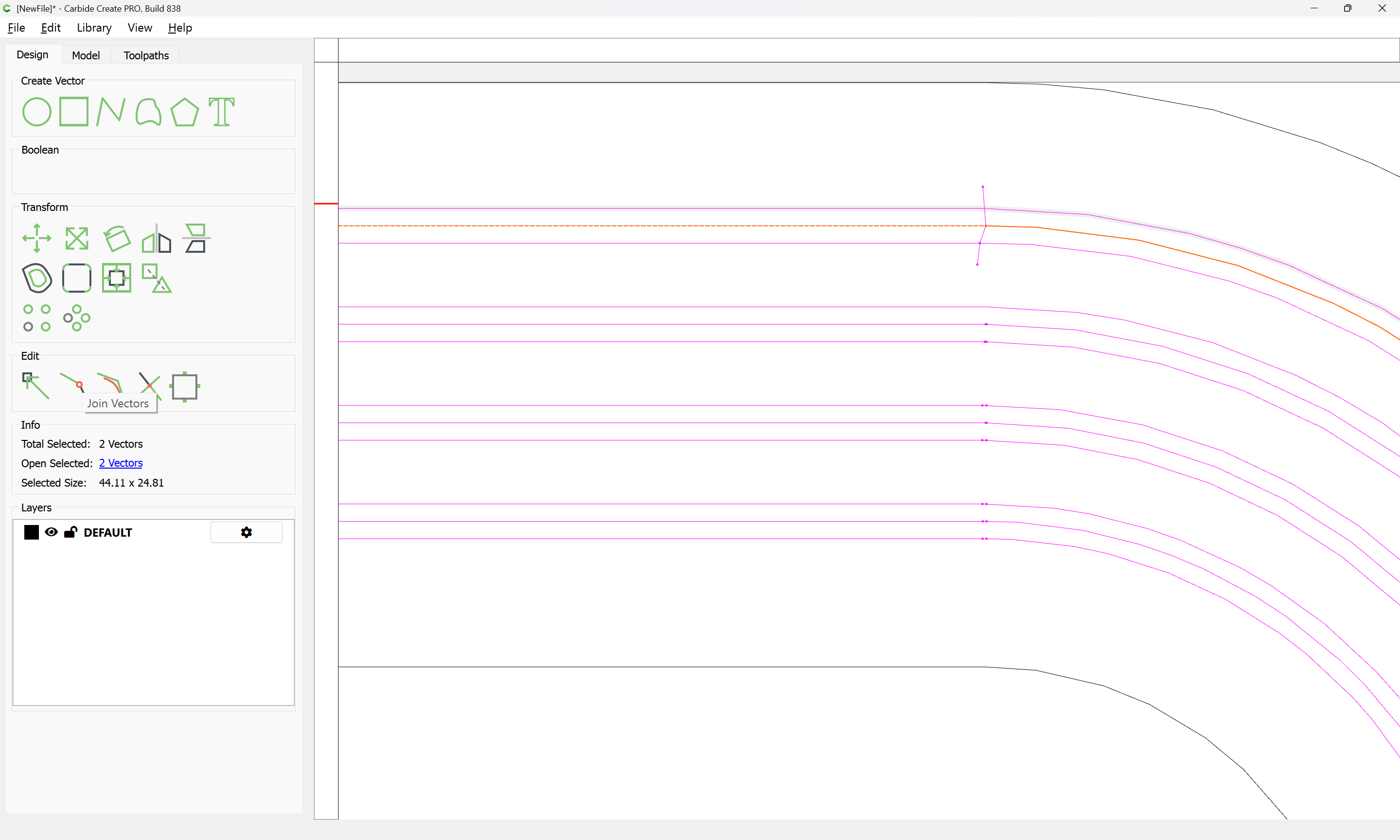
Even after I tried to “combine vectors”.
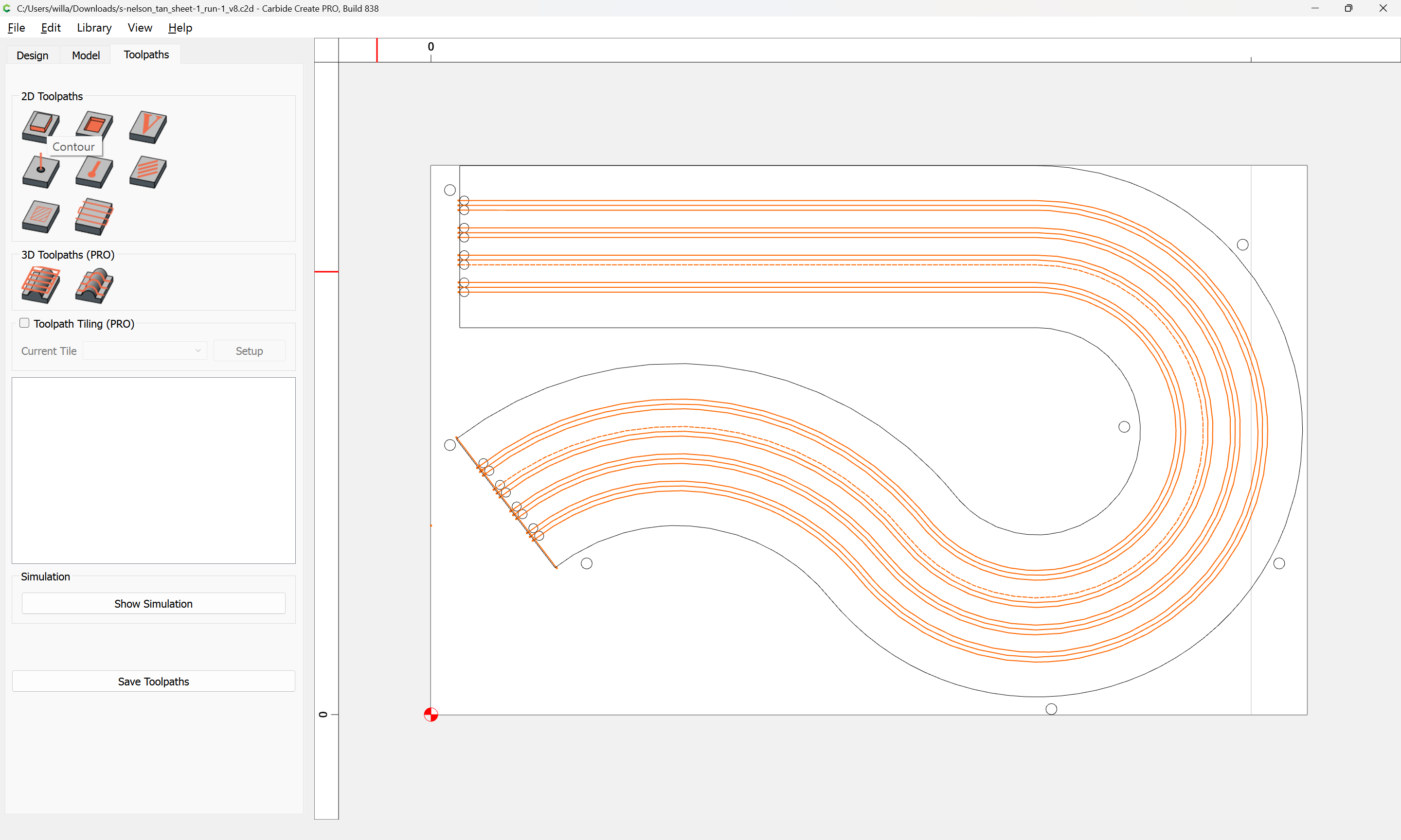
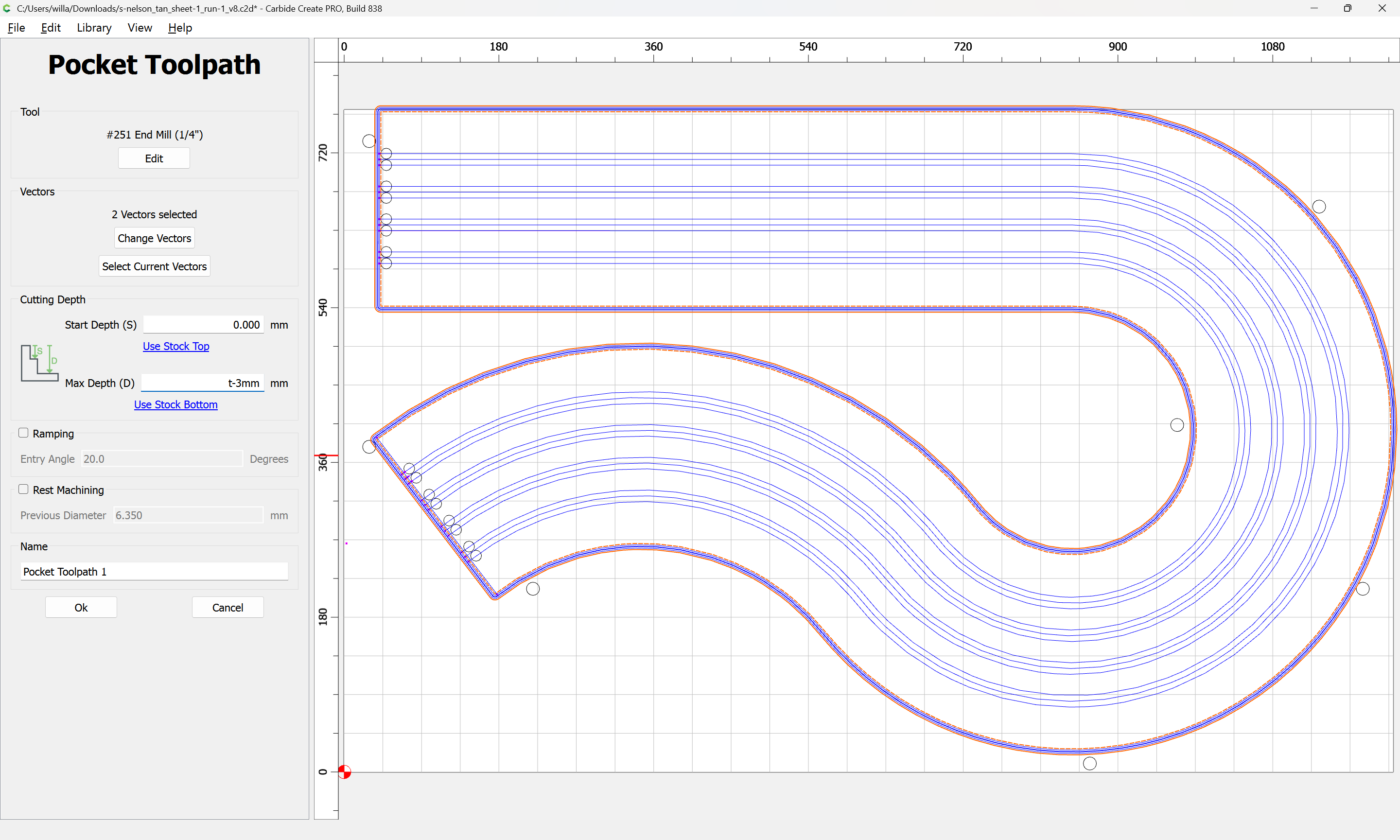
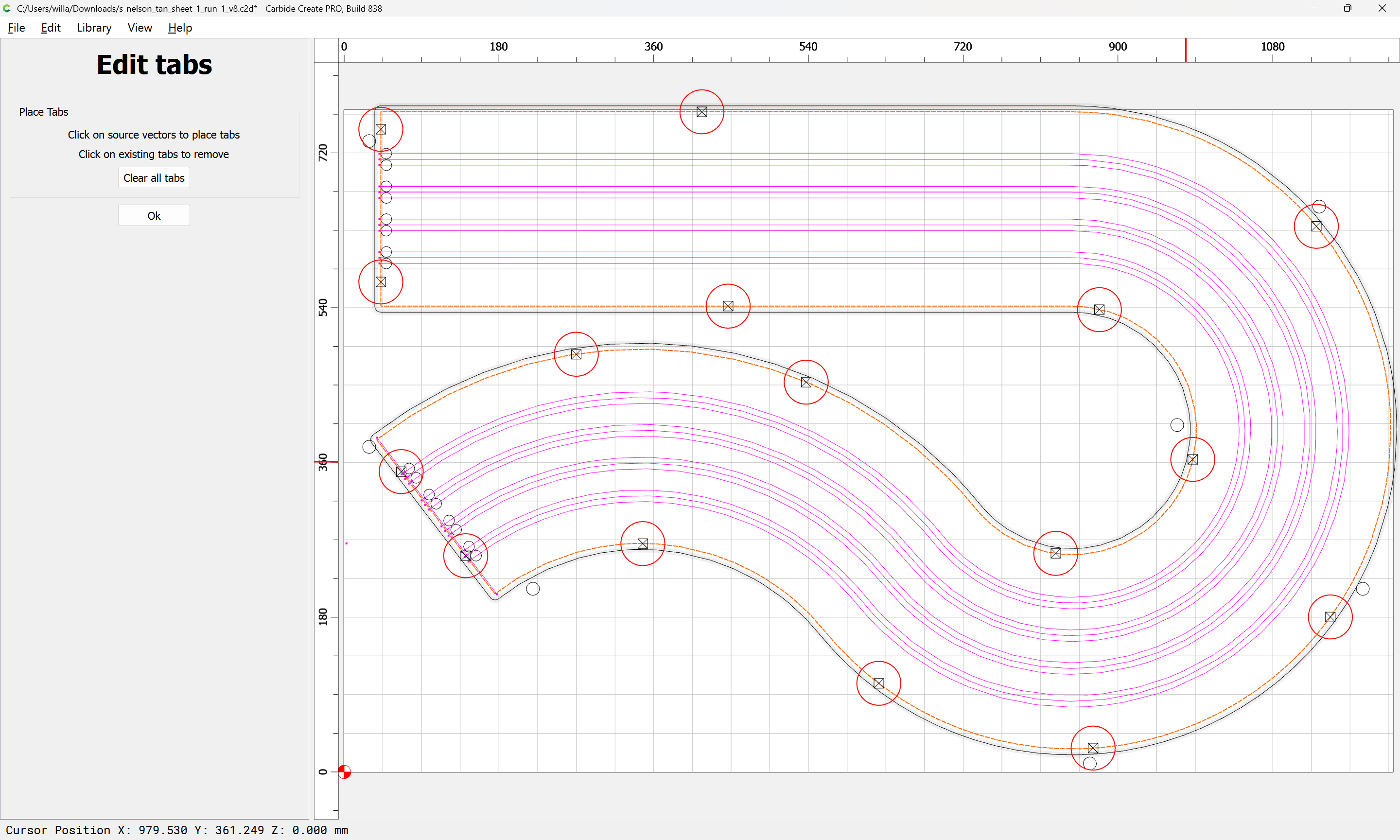
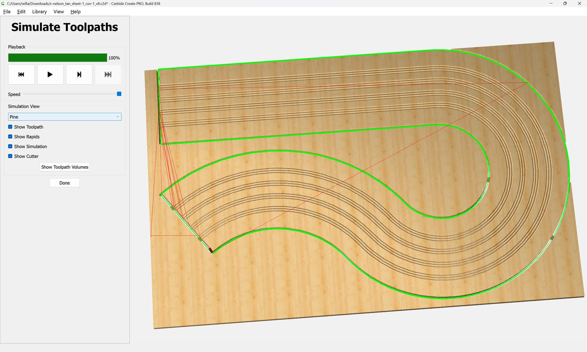
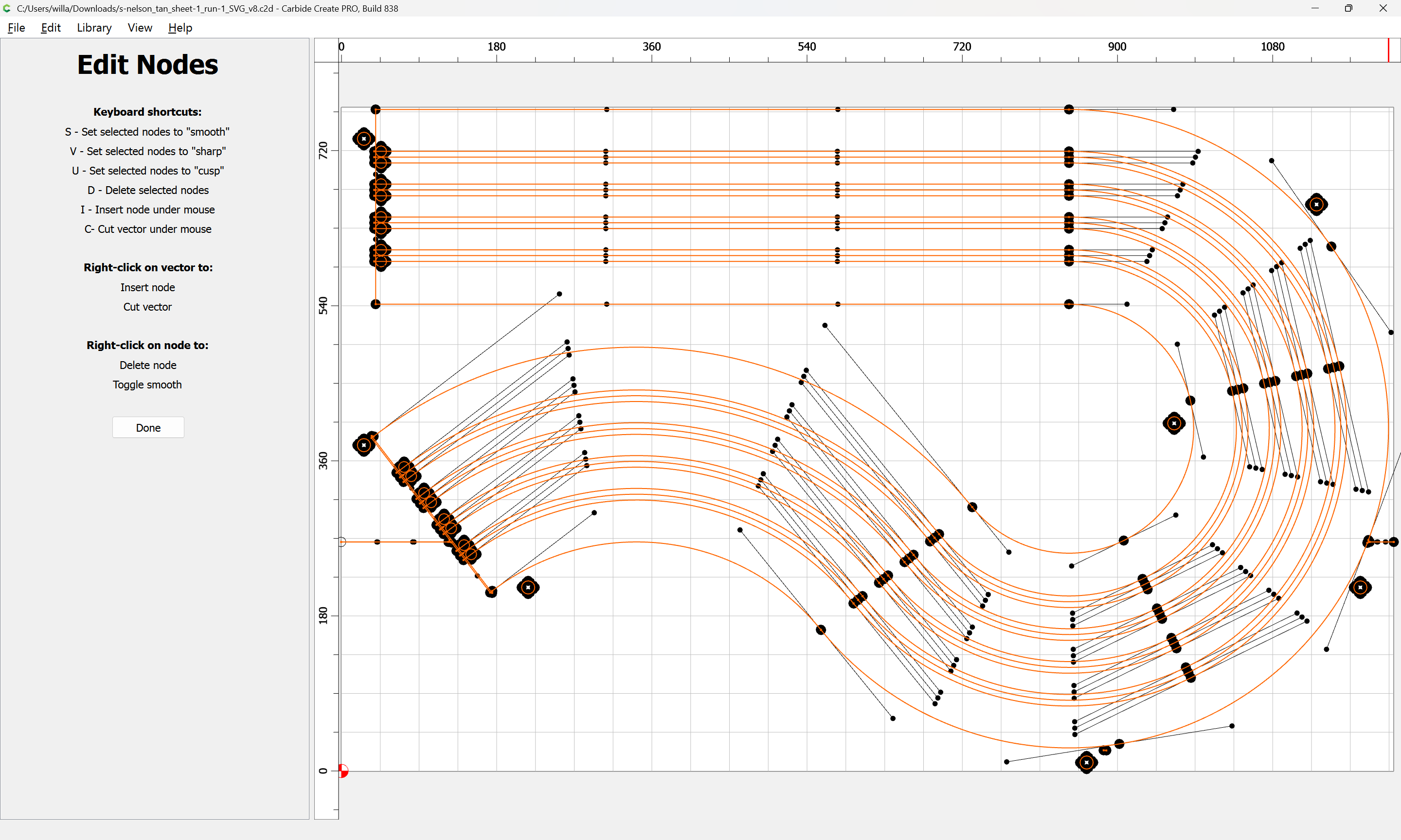
When I generate the toolpath, it zig zags all over the place.
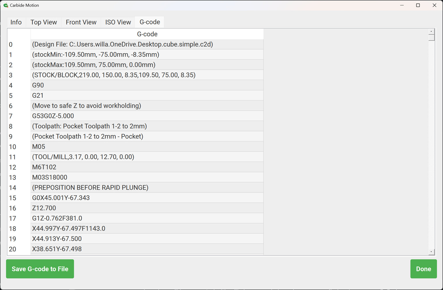
Anyways, I can edit the G code to do it more efficiently.
So I saved it.
Unfortunately, I have no way to read the G code. My last software (ArtCAM) saved as a .txt file
that I can read in Notepad.
I don’t recognize what type of file Carbide saved as. It saved it as an .nc file.
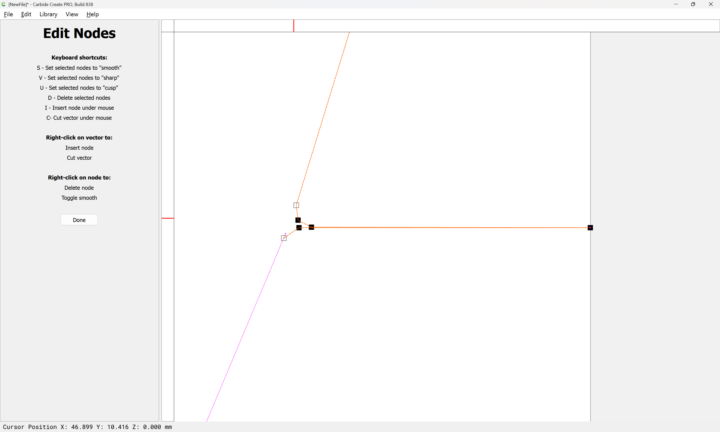
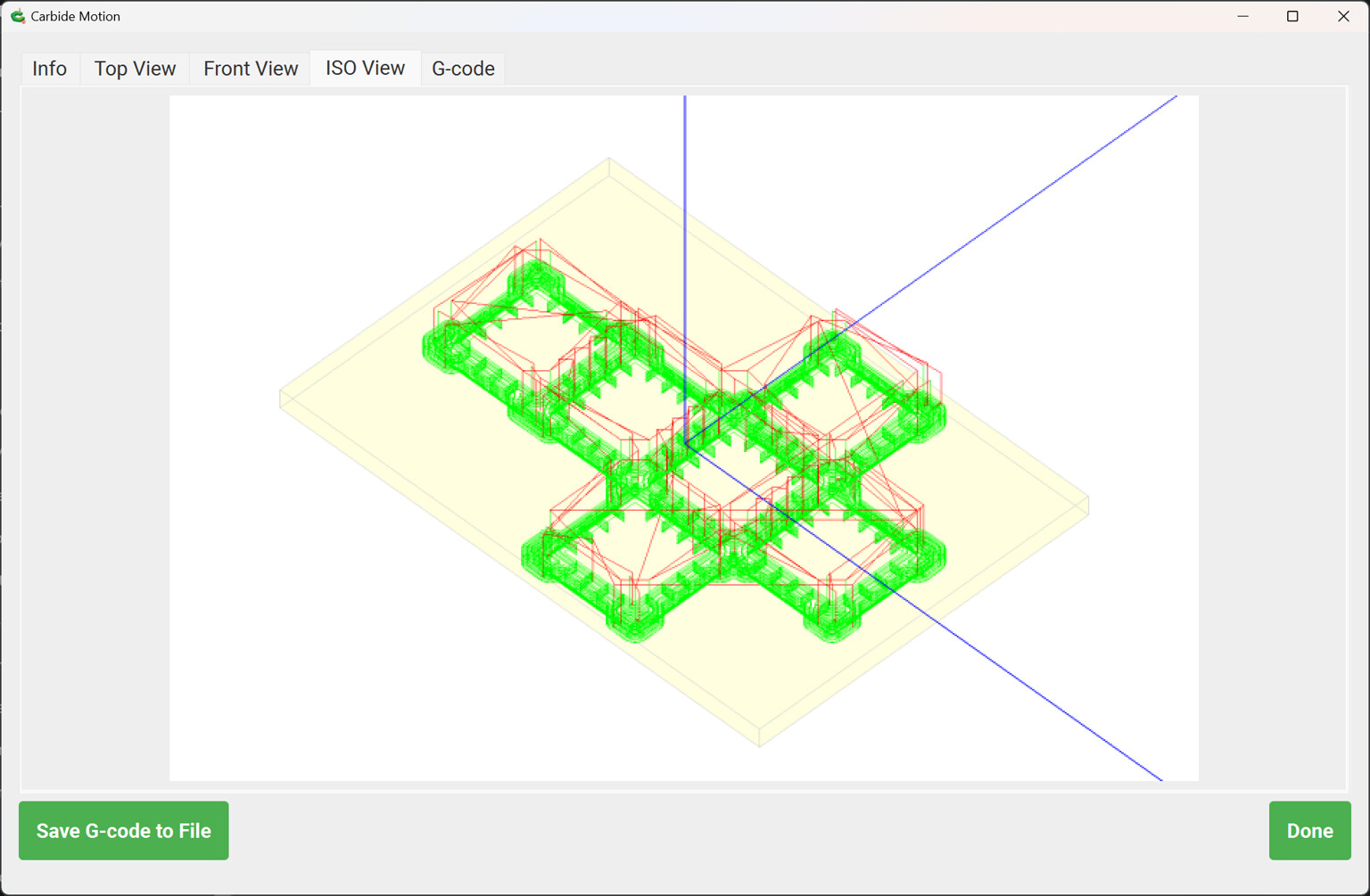
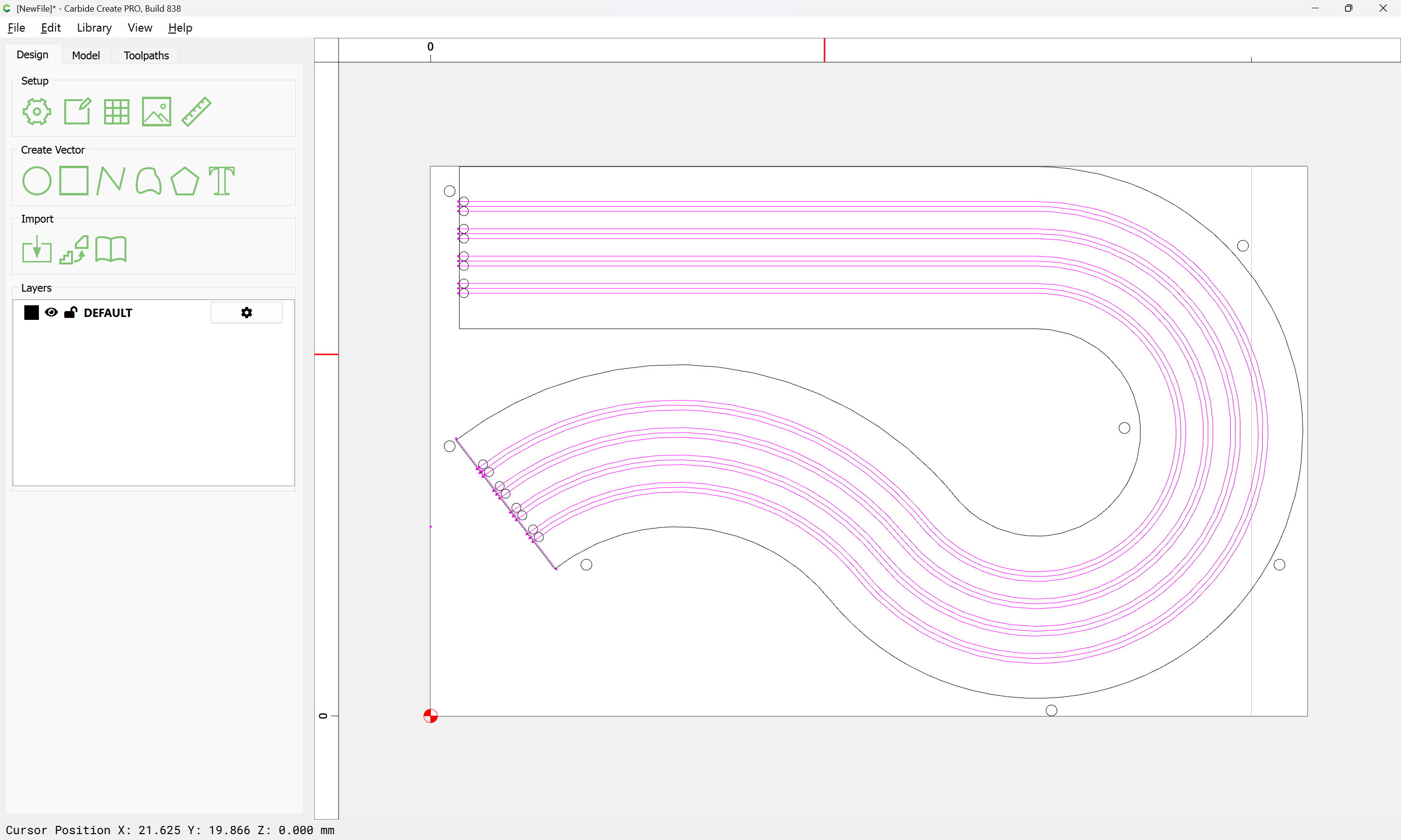
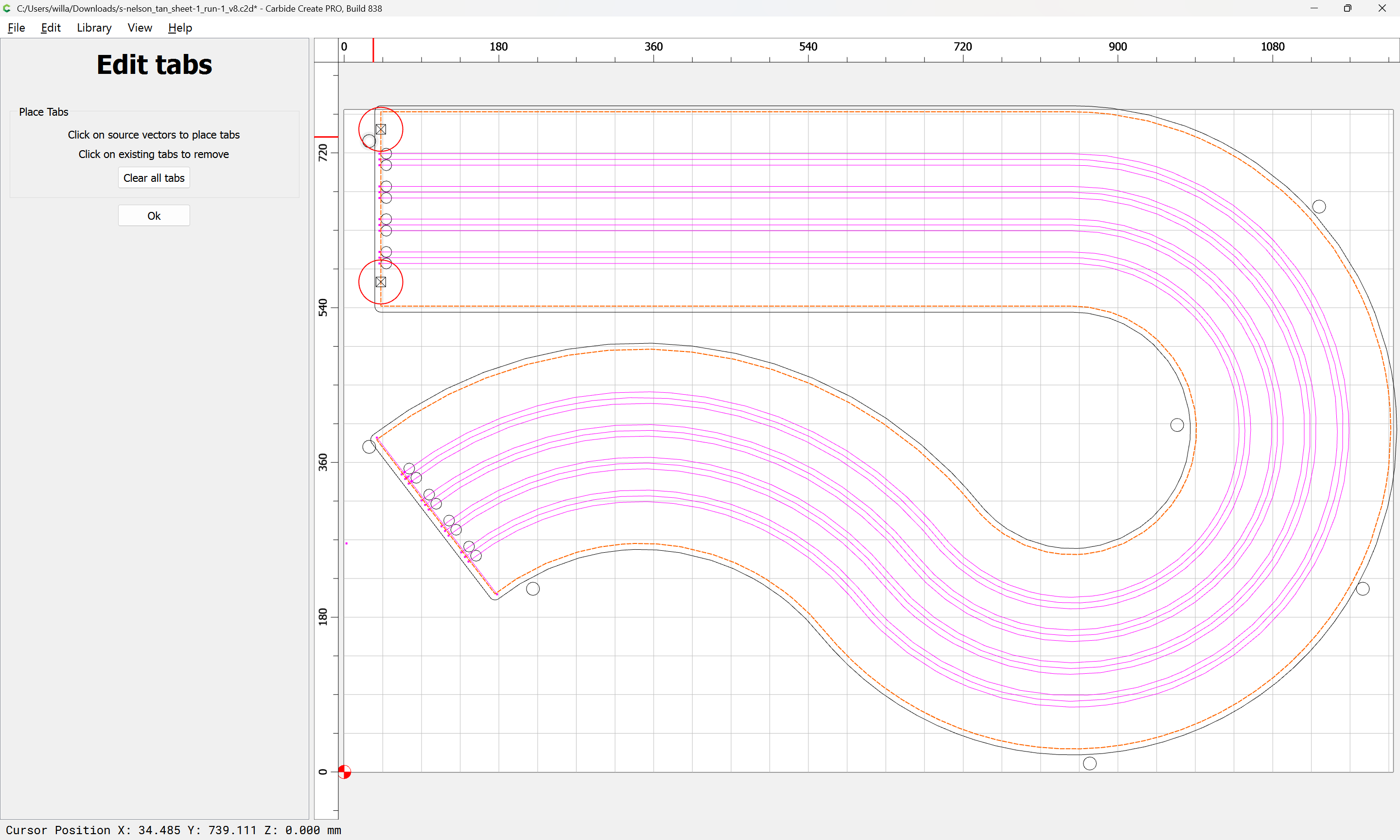
As I told Brandon…Those are there on purpose. They part off the excess material so the material can be moved up for the next cut without interfering with the spoil board.
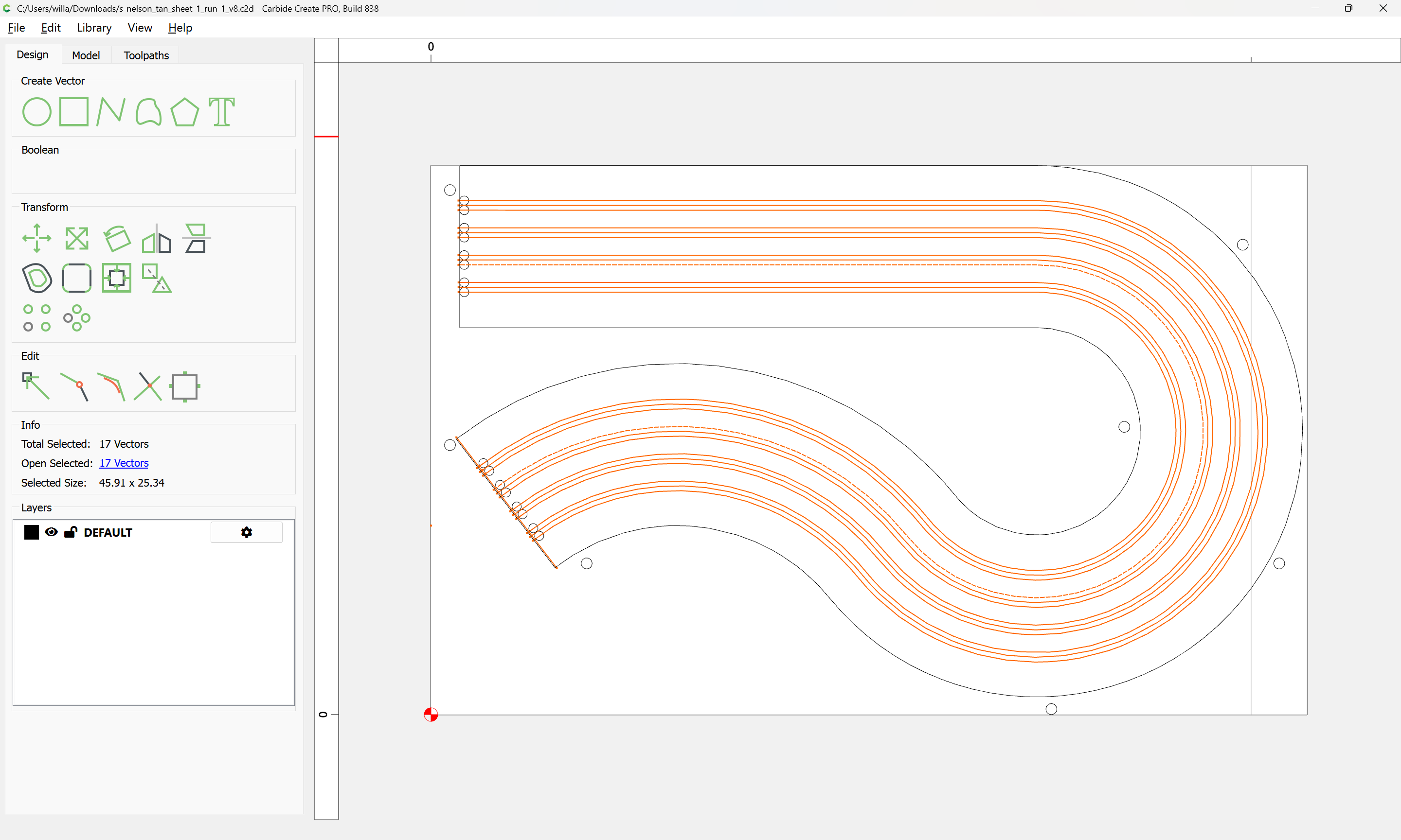
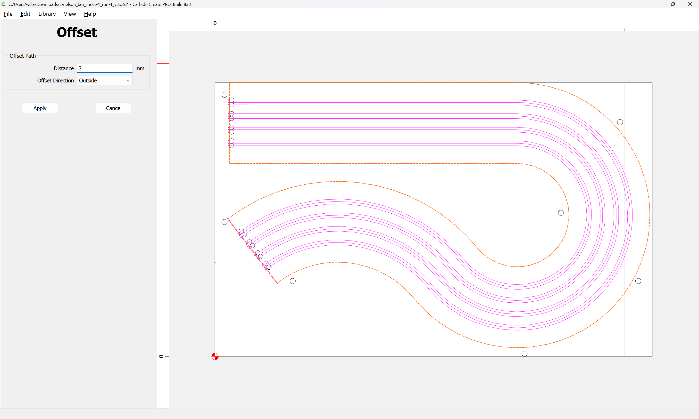
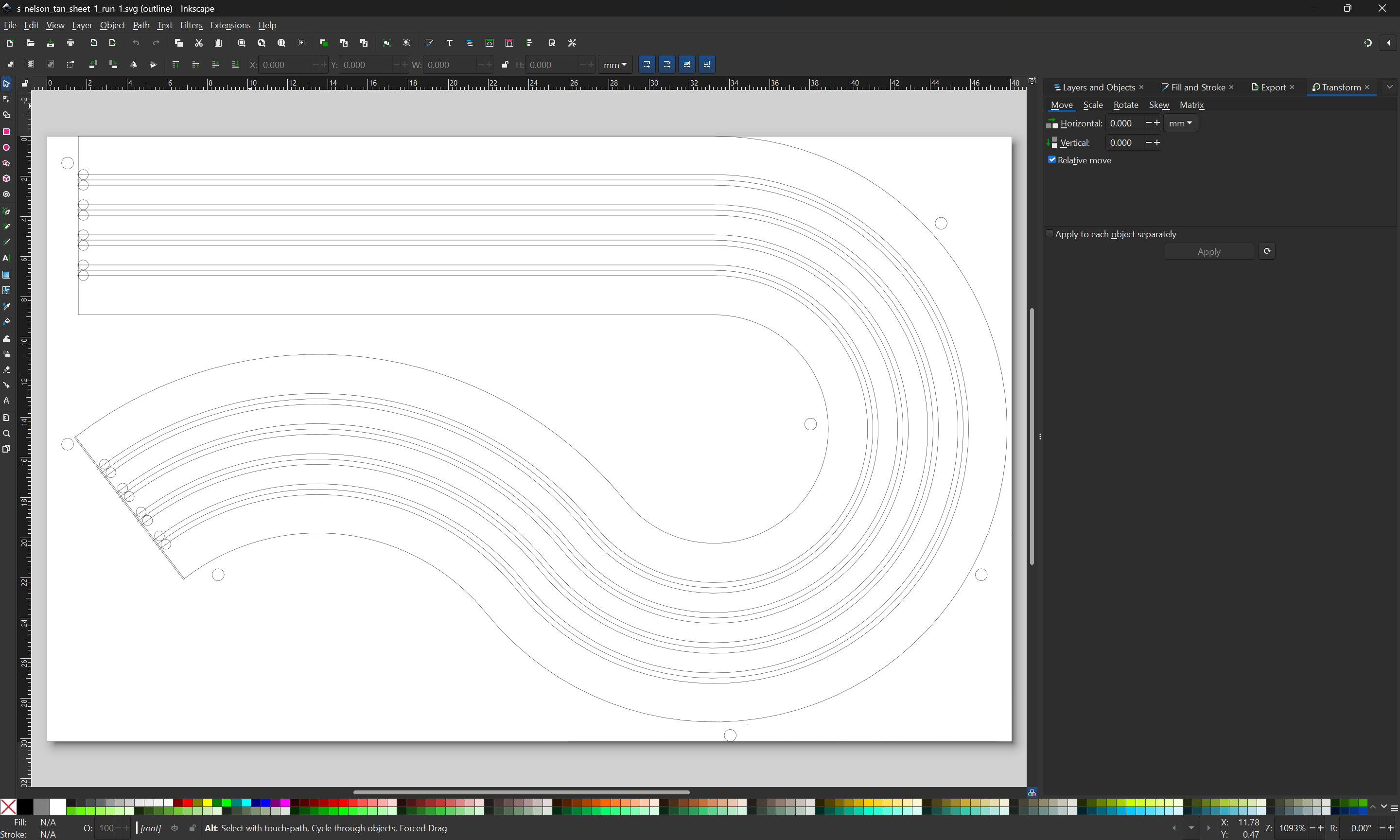
I don’t know if this will help but PixelCNC automatically joins DXF elements into a path, and there’s a tolerance setting for how large of a gap that can exist between endpoints before it stops auto-joining geometry when loading a DXF. You could import the DXF as a paths-layer and generate your toolpaths in there, or turn around and export the paths-layer as an SVG to load into CC.