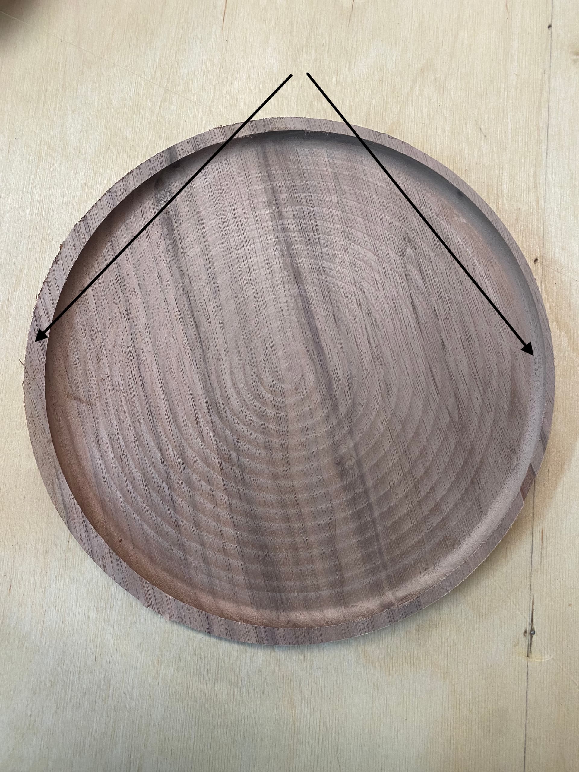
I’m making a large batch of round trays for a client. The top side is cut out with a bowl & tray bit, then I flip the blank and a use a bull-nose bit to do the bottom, which has a fairly large chamfer.
Originally I had been cutting the tops with the bowl bit and then swapping out to an endmill to cut the trays out, then using a router table to apply the chamfer. This method took WAY longer, and yielded worse results than just doing the trays entirely on the Shapeoko in a flip job.
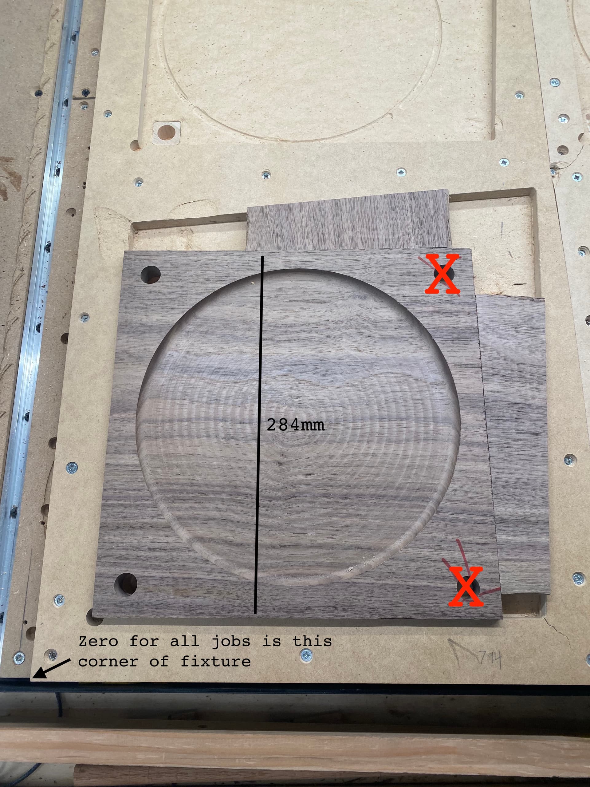
It was working fine for the first 20 or so trays. Then something changed, and now as you can see the alignment is not correct.
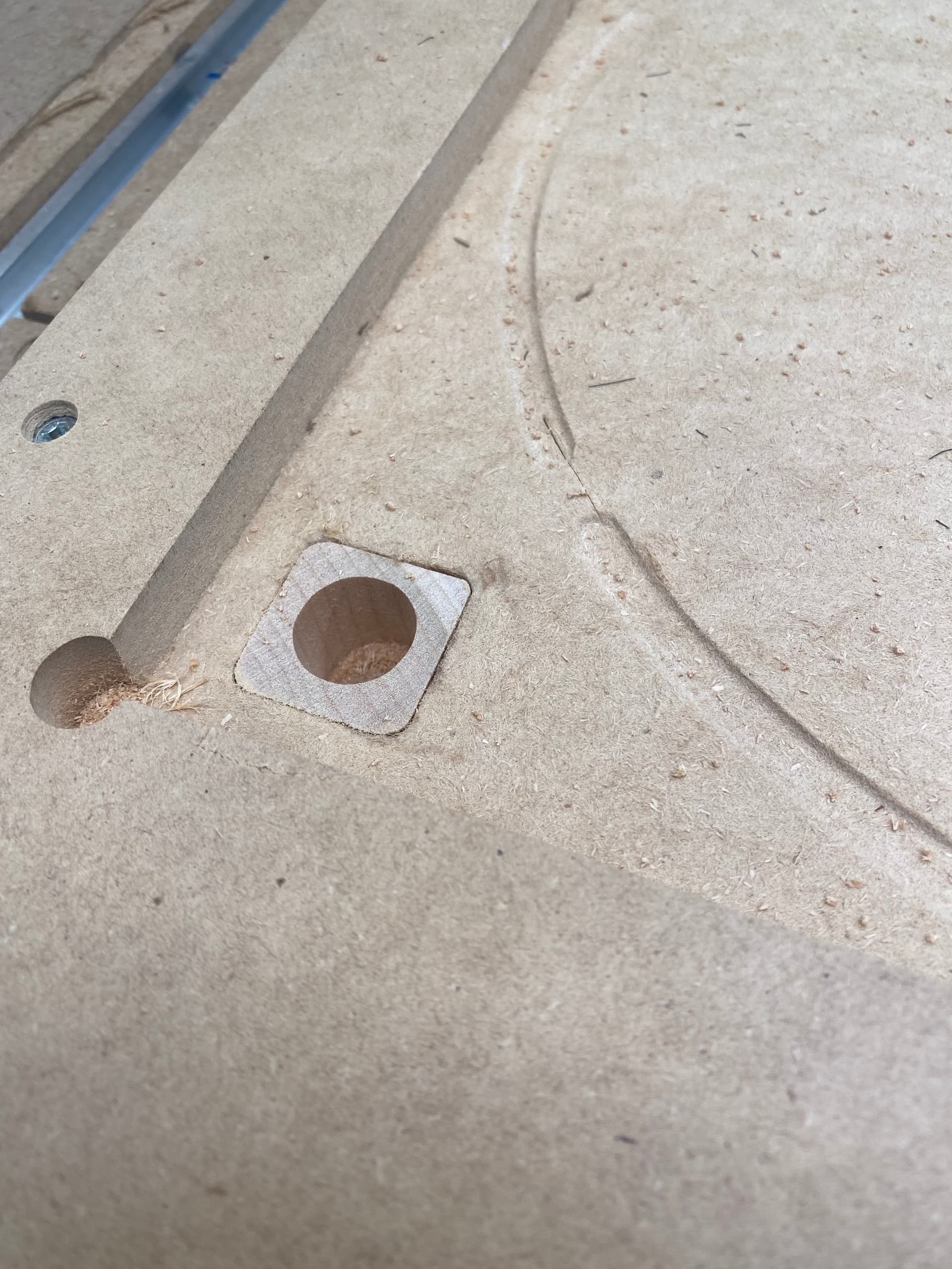
I initially thought the issue was being caused by the alignment pockets becoming too loose, and so I replaced the MDF at the spot where the holes go with a much harder plug.
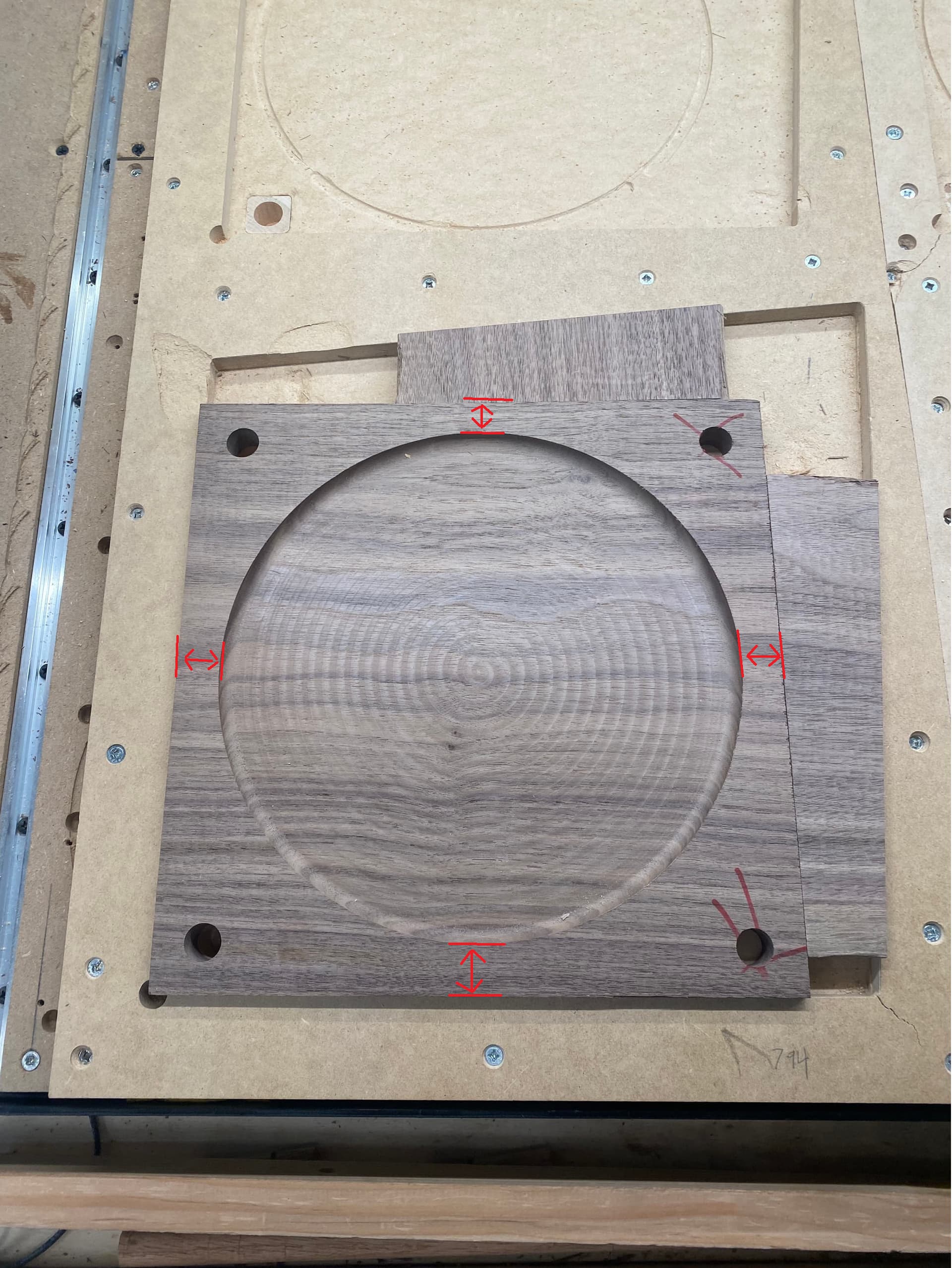
It could just be the camera angle but in your picture the spacing around the pocket especially top and bottom spacing do not look equal (the same). If this is the case when you flip the part over to mill the other side maybe the direction you flip/rotate could be throwing off the alignment.
The way I understand the layout, the bottom fixture holds the blank while Joshua machines out the dish and the 4 dowel holes. Then he transfers it to the top fixture with a flip in the vertical direction. We can’t see the whole top fixture, but hopefully it it has 1 more dowel pins above the field of view in the upper left.
Joshua:
My concern is that the walls of the upper fixture seem unnecessarily tight on the left side and lower side. The two dowel pins and two walls create 4 constraints, which is unnecessary and probably cause more troubles than it helps.
The other question is how do you locate the machine with respect to the fixture/workpieces? Are you using the outside of the fixture? Are you using the dowel pin locations? I’m surprise this worked for 20 pieces.
The spacing should be pretty much equal. But looking at the photo with fresh eyes, it does seem to be misaligned. I’ll have to check when I get to the shop and see. I wonder if I lost a step or two at some point when machining the first sides.
Hi @kelaa,
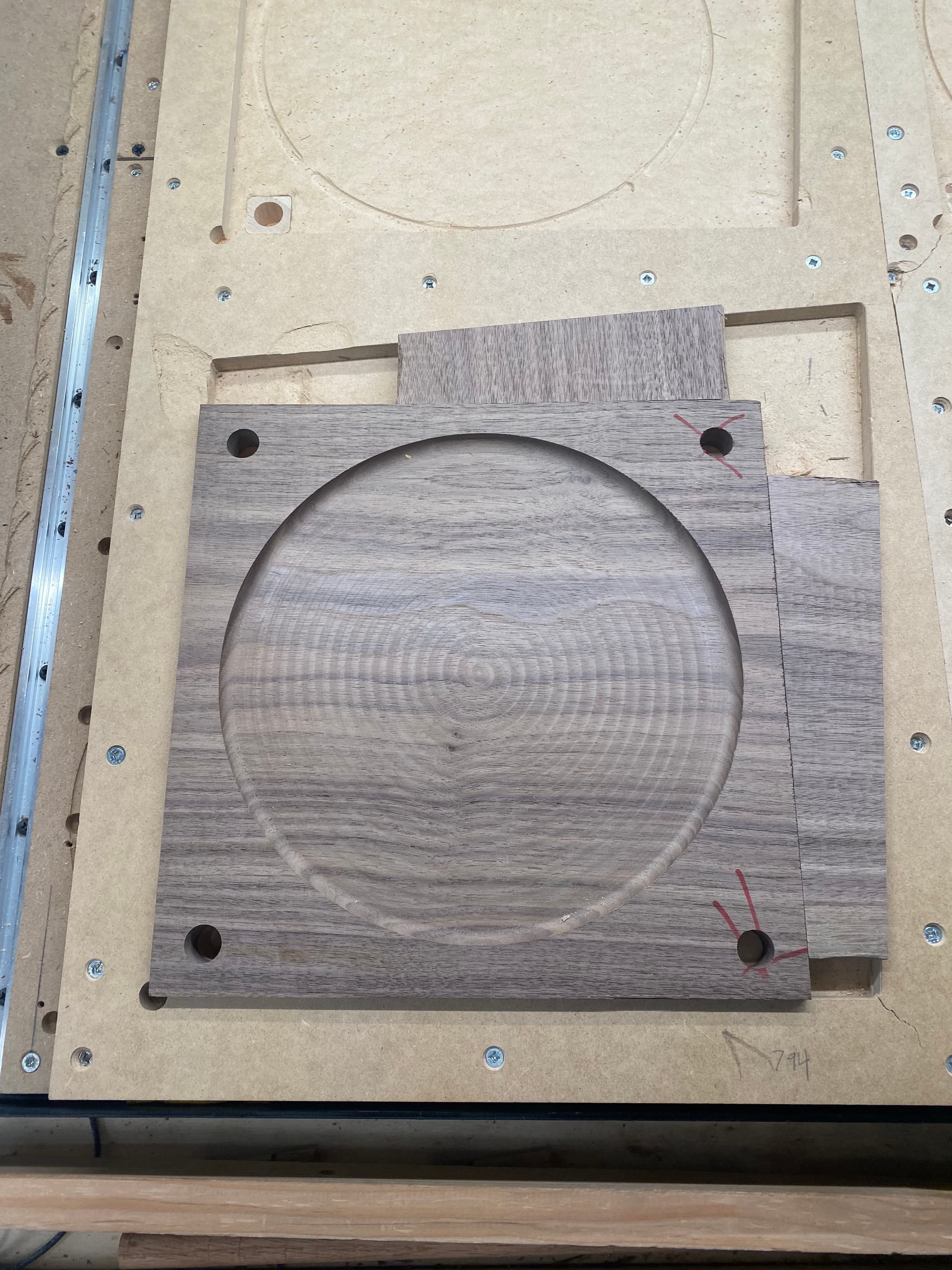
I’m sorry, I realize I was not clear about the way my setup functions. Each blank is flipped within the same pocket. I use this board to make them in batches of four. So, I machine the top of four of them with the bowl bit, flip all four, then do the bottoms with a bullnose bit. Since the zero is set for all jobs to the corner of the batching board, it should absolutely be possible to do dozens of them before changing the tool, which is the goal.
When it’s time to flip, as long as the blanks are 284mm from top to bottom, they should line up with no issue. I have made literally 100s of things using this method. The only difference is that this time I’m using wedges to hold the blanks. In the past I’ve used threaded inserts in the batch board and then put screws at each corner, but the wedges are much, much faster.
Alignment is primarily done by the bottom left corner of each pocket. The dowel pins were just to double check that the blanks were flipping properly, since this is my first time using wedges for work holding, and I like to be able to check things. As I tested, though, I began to notice that I could fudge the alignment a bit just by tapping the wedges. I suppose this is the danger of MDF.
So I started using the pins to ensure that fine alignment is perfect. As I’m typing this is realize there is no way the pins moving is what caused my misalignment problem - the margin of error is too large.
Please ignore the holes on the right side of the stock, they were leftover from an early test and are not used for this.
Could this have been caused by some machine issue I haven’t thought of? I’ve checked every v-wheel and belt multiple times and they all feel fine. I have the HDZ, in case that matters.
Okay, I see. So we can assume none of the dowel holes exist/matter, and that your stock is at least parallel top edge to the bottom edge bottom, with a distance of 284 mm. That means if you flip vertically, the left-right relationship doesn’t change during the flip. If you flip horizontally, then the left-right width also must be well controlled at 284 mm as well.
If you haven’t changed the flip direction, my other guess would be the zeroing sequence. Are you doing it manually? Have you offset the tool diameter properly? For instance, if you are probing the bottom edge of the fixture with a 1" diameter bowl bit, when you hit the fixture, your actual location is at Y = -0.5". Or if you don’t align the 2 carbide sections of the bowl bit correctly to your fixture, you could be a bit past Y = -0.5", at Y = -0.45" for instance. Did you change what you bit you are using to zero and forget to update your calculations?
I actually zero on the corner of the fixture using the C3D touch plate and the #201 C3D endmill. Then use whatever bits are required by each job. Once I’ve started production I generally don’t re-zero until I’m through. Since I’m using wedges, I was worried the batch board might move from tapping, so I put in tons of screws to prevent that.
I’m becoming more and more convinced that I lost some steps when machining the tops.
Seems like either your workpiece is not in the position you expect after the flip or your zeros are different between the ‘bowl cut’ gcode and the flipped ‘cut out’ gcode (or both).
Former should be pretty easy to check by using a calipers to check the distance from the top edge of the stock to the top edge of the bowl cut. This becomes the bottom edge of your stock after the flip, right? - and this edge (rim) ends up to thin or too fat after the cut out operation?
Sssuming yes, once you have your calipers measurement, look at your flipped cut out gcode in something like ncviewer. In ncviewer, does the cut happen where you expect accounting for your Y offset and the width of the cutter?
For the latter, follow your normal set up procedure to load the bowl cut gcode (zero if you do, etc) and jog the machine to a RELATIVE position of say Y= 12.00 make a mark. Follow your procedure and load your cut out gcode and jog the machine to the same RELATIVE position. Is the Y centerline of the cutter in the same position ?
Have you determined in which direction the misalignment is occurring, is it all in the X or Y axis or a combination of the two. This could help in tracking down where your problem is.
So it turns out that Patrick got it right. I somehow lost a few steps - about 4mm worth - in the Y direction. Very likely my dust hose got bunched up or something. Luckily only a few of the blanks were machined wrong.
I got so focused on the idea that something had gone wrong with the flip operation that I forgot to consider the more basic, likely, and obvious possibilities. So lesson learned.
I have found it can be useful, where there is room on the stock, to machine a validation feature.
On some of my double sided Aluminium parts for example, I bore a marker hole through the spare stock and then either jog to that X, Y or have the first toolpath ‘bore’ the hole as a sanity check after the flip to make sure things are in line. It means you see it quickly if things are off by a significant amount.
This is an excellent idea, thank you. I’ve been considering doing something like it for a while now, time to get it going.
I had been using the dowel holes for this - to check that the alignment was good I created a 2mm deep contour around each of them, which should have worked … except when things went wrong I assumed the issue was with my setup, so even though I saw there was an alignment issue, it didn’t occur to me it was due to lost steps. Oh well. Next time I’ll get it!
Figuring out which dimensions are really ‘reference’ and which are relative to whatever error was introduced, it’s really easy to either convince yourself that up is down or that everything’s fine when it isn’t.
I’m currently doing a part in Aluminium, I have an MDF jig as there’s only a few of this part to do. I used CA glue to reinforce the MDF at the dowel pin holes and bottom left machined edges which I use to zero from, all the work is done in “Jig Zero” coordinate space.
I messed up the first one due to my own mistakes and now I have the following
Machine the dowel holes and counterbored hold down bolt holes in the stock, only relative position matters
Bolt the workpiece to the fixture, zero off the jig corner
Put a 5mm dowel pin in the spindle, go to X Y zero in CM, jog the Z up above the part and say “G91 X28 Y40” and check my pin is exactly over the dowel pin hole.
As I get more used to the workflow I may mess up less, or more, time will tell
Also, I learned to put a dial indicator in the spindle and tram the jig straight along the Y axis so my flip errors don’t increase with distance from Y0.
I’m still struggling with this job currently. The MDF batch board is just being a real pain - it seems to be moving at random times. It also moved pretty significantly over the weekend. So that’s not good. I think maybe for wedge work holding MDF is not sufficiently strong. Or maybe the temperature fluctuations in my workshop are messing with it. Very annoying.
Is the board itself staying in place and ‘square’ to the machine, figuring out if it’s the jig moving or the workpiece in the jig would be a key step to diagnosing problems.
You could jog to the locations of a couple of your dowel pins and check if the jig is still square and where it’s meant to be?
I’m starting to suspect the entire wasteboard is shifting around. It’s very odd, but yesterday I had to re-mill the corners of two of the pockets because they had become unsquare. The relationship of the dowel holes to the walls of the pockets should always be the same, but it seems to change somehow.
I think it may have to do with temperature changes in the workshop - my workshop is only marginally heated, and not at all over the weekends, so maybe things are moving around from that? I’m going to remake the batching board from much heavier duty baltic birch plywood, and see if that will finally behave itself properly.
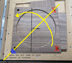
Crazy thought, but why not use the same “J” corner (blue) for both sides?
Flip the job 45° about the lower left corner so that corner stays in the same spot.
You of course have to make sure the center of your circles are the same distance from left & bottom,
But I suspect you’ve done that already??