Has anyone explored yet using the flip jig to mill double sided pcb s to assure alignment? Or would that not work?
I think you need to make two sloted jigs for each side to hold the board but if you had that I don’t see why it shouldn’t work. The whole idea of the pinned flip jig is that it is very precise.
Tho in thinking about it, the boards are very thin so you’d probably need a backing to keep it from flexing that you could move to the other side. Starts getting overly complicated I suppose.
I have not tried this, but will note that milling circuit boards requires that the board be pretty much dead flat and parallel to the machine x-y plane. I’m not sure how this would be achieved with the flip jig. I should imaging there are a number of ways to do this, and if you work it out, I would love to know it.
I actually do board holding either by supergluing the board to a leveled section of the wasetboard (for small boards) or with a really, really crummy vacuum setup I made that uses a mini shopvac (for large boards only due to poor vacuum and low holding… maybe 20KPa or so). Most of the things I don’t want to wait for from a commercial board shop are one sided and small, so superglue isn’t an issue as the back is non-critical.
Circuit board is stiff and the flip jig is narrow, I think just two circuit board thick slots in some wood would work fine, you could even mill them on the nomad so they are true and the slots are right in the middle. As long as you don’t go really hard on the feeds and speeds it would have to work. If you made each piece of wood the same width as the flip jig you would not even need to worry about centering it each time, just get it flush with the flip jig.
of course if you made them of acytal or even aluminium would be best but more time consuming to mill, if you make them on the nomad
Heres a couple photos and a Carbide Create file that could address 2 sided boards.
I have not completely tested it, but in theory it should work if you can place the origin in the center of the board.

PCB Mount.c2d (240.4 KB)
This Prototype PCB FLIP Fixture uses the same theory as the Carbide Flip Frame
- Pins and Center Rotation -
However the Frame consists of 2 parts that sandwich the PCB board, with no tape or drilling.
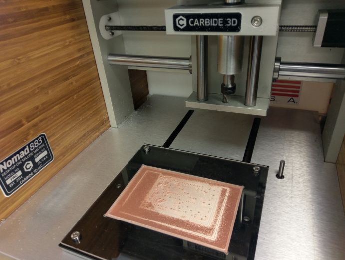
First Test of the PCB Fixture - Note: no pins needed for this 1 sided board, but the ability is there.
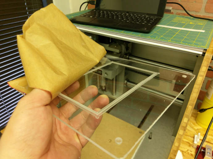
The top part is a clear 8"x8"x.125" acrylic top sheet that has a pocket that holds a 4’x6" PCB black but also a thrugh hole operation that creates a thin lip to hold the perimeter 3mm of the board. NOTE: This is machined upside down to create for the step/lip.
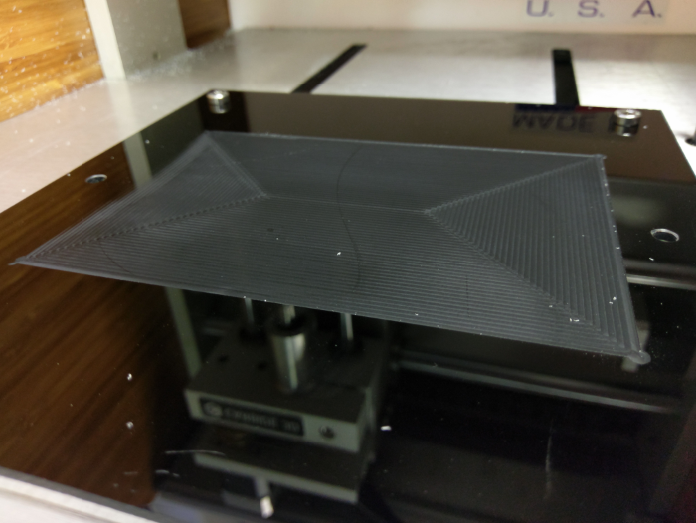
The base of the PCB flip frame is a black 8"x8" x.125" acrylic that is located to the Nomad table using the 6mm Table holes and corner M6 x 10 hardware, the pocket operation serves to level the machining surface and capture the PCB board blank.
1 Like
hey that looks cool!
So let me walk through how you would use… The board is captured by the top piece as it screws to the bottom one and the table. After milling the top of the pcb, you’d un bolt the assembly, flip the pcb and then re sandwich the new side down And reboot Correct?
Maybe someone can weigh in here if the PCB-GCode let’s you set the origin to center…
1 Like
@sshwarts
Yes those would be the steps.
The black and clear plates have through holes in the corners.
The lower black plate stays in place using the pin locations of the table.
The lower left corner would also work for the origin.