Looking for some ideas on how to improve the accuracy on my zeroing technique for flip machining. I have always been using a lower left zero point at top of stock. Well, when I flip the part, that becomes the upper left corner. I read on another forum thread that @WillAdams reccomended always using that same corner even after it’s flipped. I use a 60deg V bit point to set zero and then load the required tool on the first OP. I’m guessing that the slightly less than perfectly square corners or vertical face is lending to a .05mm (roughly) difference from 1st OP to 2nd OP is attributed to not using the EXACT same corner after flip for re-zeroing. The difference varies part by part from being off on the Y or the X.
Hoping to learn some better techniques for flip machining and maintaining an accurate zero.
Precision has to start somewhere — for this, it starts with a perfect square corner (or ideally overall block) — then, each subsequent operation begins to stack potential errors/shifts, and if the block is large, it’s even possible to heat it up sufficiently that it expands.
I’ve pretty much switched over to machining a pocket in a piece of scrap to receive the part for the flip.
I may have to look into making a set of soft jaws for the mod vices.
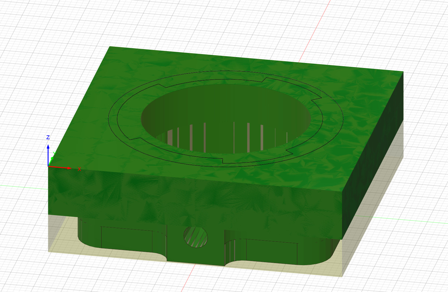
Sounds like I need to face all sides to ensure accurate dimensions before starting the machining. The current block is small (51mm x 51mm x 16mm) since I’ve been trying to dial in the tool paths. Once settled, I’d like to move to a larger piece of stock to run the parts in batches. @WillAdams are you using a touch probe or bitzero?
Kevin’s way of doing this is to machine the outer profile so he knows it’s as perfect as he can get it.
I’ve also recommended using the same corner as a zero point for everything.
I’ve also recommended not moving zero if possible.
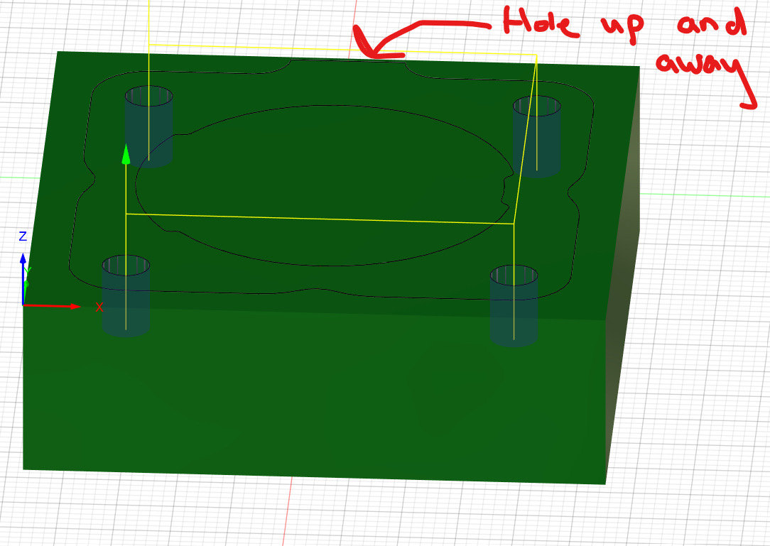
The way to do both is to flip the part around a 45° angle through the zero point, keeping the “J-Corner” in the lower left. In this case the hole on the side of your part would move from the front to the left side.
Using SMW vices and a touch probe, I design my machining such that when I flip the part, only surfaces that I have machined are touching the vice and then I reference off a surface I have cut. If there is nothing possible to reference off of, I will add a little extra to the stock and drill a through hole in the extra stock to indicate off of.
Since you mentioned it, I thought you had a touch probe already… To use a touch probe to probe the hole or any other machined surface that isn’t one of the corners will also require that you switch to CNCjs or gSender. CM doesn’t have that level of flexibility and doing the probing using the MDI or even quick actions sounds painful to me.
@Tod1d i would like to not rezero at all but since I am taking some material off of the XY on the 1st OP, when I flip the part it shifts a little to the -X direction.
The great thing about the v2 BitZero is that since it is probing the center of a circle it is invariant of size/geometry (so long as geometry is such that it is uniform around the effective perimeter at the depth which the tool is placed).
I use CNCjs myself and I am very comfortable with technology and have been working with 3d printers for years before getting my CNC so I am also very comfortable with gcode and macro programming. I didn’t find it too hard but it is a very big change. For CNCjs you need to have macros that do all the probing and the changing of tools.
The latest version(s) of gSender have been trying to make this easier for people. Much closer to the CM motion interaction of the bitsetter. I cannot speak to how well that works. You would still need macros for all the non-edge probing that you’d do such as probing holes or the middle of stock.
In terms of your setup, I would probably run one of those 4 corner holes through the stock and use that to establish the zero for the 2nd side. This would also require that you use something other than CC like Fusion 360 (but I hope you’re already doing that if you’re machining this part) as CC cannot handle a zero at an arbitrary location.
Unfortunately, this is the best way to hold tight tolerances on an irregular shape. But once setup you can really crank out some parts and be confident in their dimensions.
@WillAdams so you don’t have to use the 1/4” dowel that comes with the bitzero? You can use one of any diameter? Some of my holes are small 3mm or so.
@Tod1d well that has been how I’m doing my flip but I haven’t been doing my zero on that same corner. I have been keeping it on the front left corner. I need to change this.
I don’t have any misting and my air assist is manually controlled so I can’t help you there.
For probing, yes, I have macros that will find the center. Since I don’t know the dimensions of the object being probed, it involves a couple (or 4 for the center in both steps) steps. To center in both dimensions, I would do the following:
Manually jog the probe near the right edge and run a macro that sets X zero off the right edge
Manually jog the probe near the bottom edge and run a macro to set Y zero off of the bottom edge
Manually jog the probe near the left edge and run a macro that probes the left edge and automatically sets the X zero to the mid point of the stock
Manually jog the probe near the top edge and run a macro that probes the top edge and automatically sets the Y zero to the mid point of the stock
I actually really like using the middle when doing a 3rd side operation. After machining 2 sides, there is enough opportunity for errors to compound and my 3rd side operations have always been adding holes to an existing surface. I feel like it’s more accurate to go off the center to counter some of the compounding errors.
Also, since you’re writing macros, you can pretty much probe whatever you want. The same process I just described could be used to probe a piece of the machined. You could probe 2 inner edges to establish zero in the corner of a machined surface, etc.