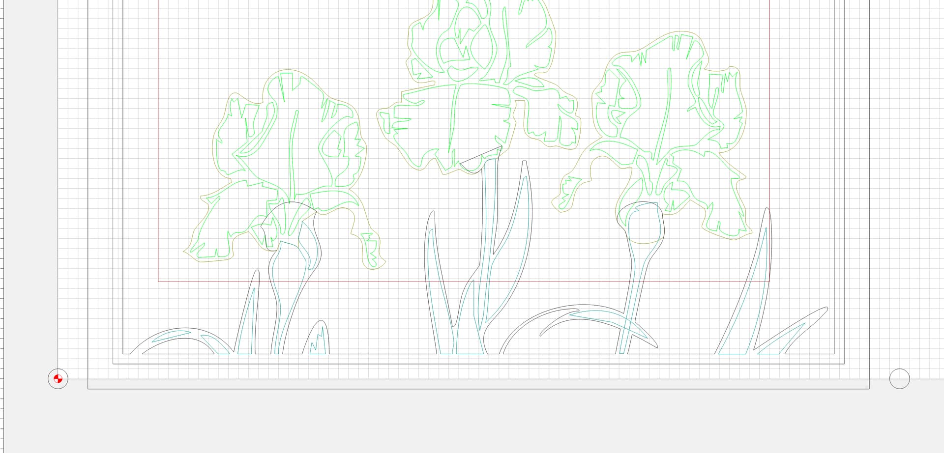
Well I/m back again with a failure. I’ve been trying to figure out a flip method that works best for me. Ive seen most of the videos but wanted to try what I thought was a “simple” approach.
For the top side of the spoon, the “bowl”, I set the tool path zero to bottom left and using Biot setter set X,Y and Z to bottom left. This carve went great.
For the bottom side of the spoon I flipped the stock so bottom left of stock is now top left iand I set the tool path zero to be top left. I then rest X,Y and Z using bit setter in the top left corner.
Well that seemed logical to me but didn’t work. See pictures below. Can someone please explain to me why this method doesn’t work??? I know there are other methods but this seemed like it should work. What did I do wrong?
First carve was bottom left, I flipped stock front to back (not left to right) and set back left so it was the same corner. What am I missing? Before I toss the CNC out a window
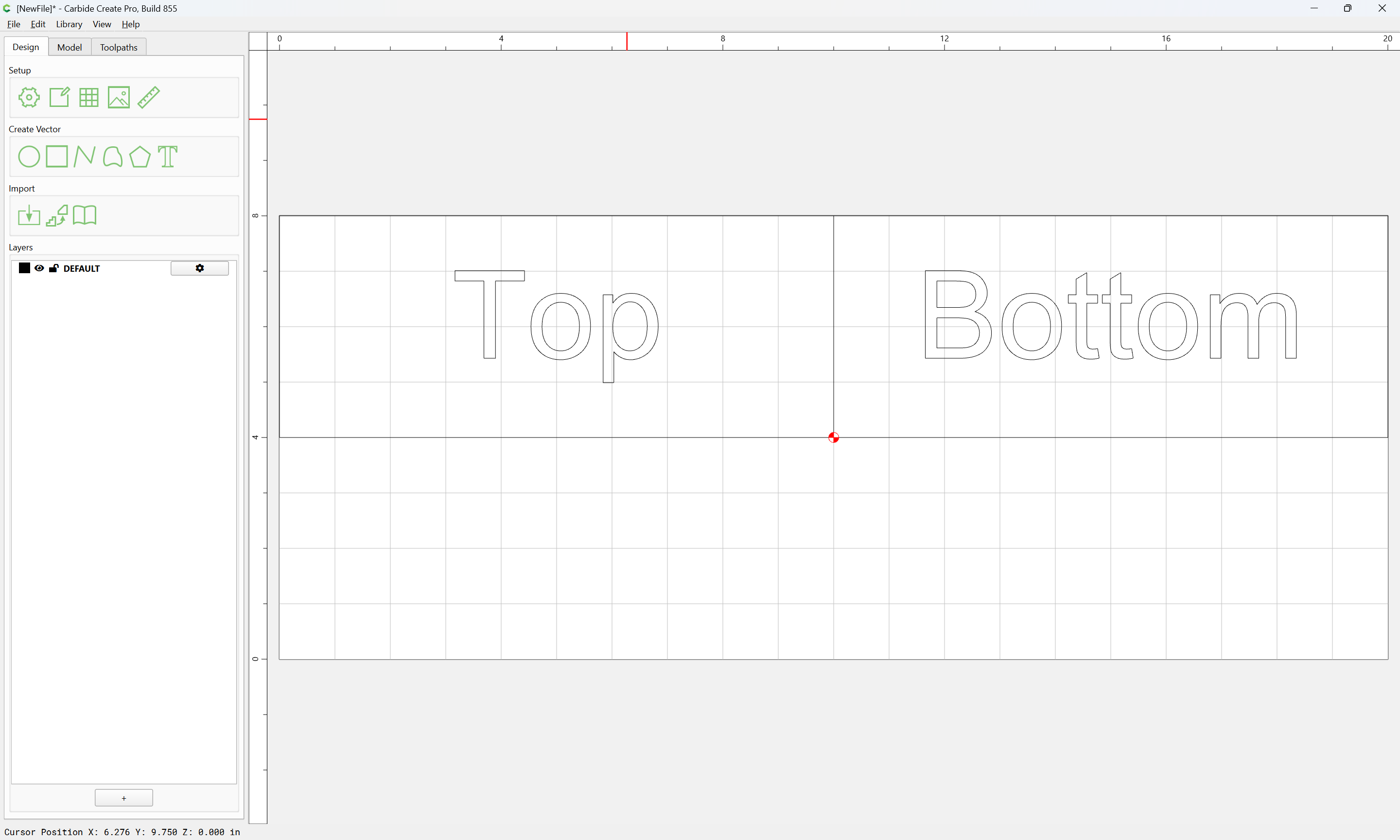
Something I didn’t mention is that I am enabling and disabling tool paths depending on if I cutting the top or bottom of spoon. I did not use the top half bottom half design like you did.
my method for flipping is to put two indexing holes in the material. one exactly on the zero and one where the zero would be when I flip. My design is centered in those two holes and I use different layers for the front/back parts.
This way, I create a drill toolpath for the two holes and i can re-align things by ensuring that the drill bit goes perfectly into the hole when I move to the x/y point manually. It also has the added bonus of letting me be sure that i’m lined up on the X axis because i can move the bit straight on that axis and it should drop straight into the hole on the opposite side.
Did you also mirror the geometry vertically and keep zero in the same spot? I draw any vector at XY zero and mirror it with the geometry. Then I have a reference to place the flip side so it’s perfectly symmetrical to the original
Thanks Tod. I have an L corner bracket to make sure the stock once flipped is in the same exact corner. The vectors are perfectly centered in CC. I carve the first side after setting x,y and z in bottom left corner. I then flip the stock vertically, reset x,y and z to bottom left corner again then carve. I created this simple example and I just can’t get it. Here are a few pictures of what I’m doing.
An L corner will only register once against a given corner and will only work if the stock is measured perfectly and positioned exactly for both sides.
So even if the stock is exactly 8” x 14” and the design is perfectly centered (middle of design is at 4”) and the stock is snug in the L bracket, this won’t work?
That’s what I thought @WillAdams. The dimensions are precise and so was the location of the stock after flipping it. I feel like there is something going on with the bitsetter or CM that’s not doing this correctly. It just seems too illogical that the method I explained doesn’t work. Then again I could be way off.
I would love to have someone take my simple test file and see if they can get it to work following this method:
Stock is exactly 14"x8"
The design is centered both horizontally and vertically
Enable/disable the model and tool paths according to which side (top/bottom) I am carving.
Set the X, Y and Z to bottom left using the bit setter
Carve the top which is just a recess on the center of the stock
Close CM
Open CC and edit the file to enable/disable as needed for the bottom/back carve
Save file/toolpath
Flip the stock vertically
Reset X,Y and Z using bit setter at the bottom left position as before
Proceed carving.
I would expect the recess should be in the center of the profile contour cut as it shows in the simulation. It is not.
I can not attach the file as it’s too big. I will send it anywhere you like or create a link if someone would try it,
Purely from an observational (and trouble shooting) standpoint…
Just using a ruler, which of the two cuts is NOT centered. That will likely help indicate where your problem is. (From the photos, hard to tell but it kinda looks like the first cut might be centered and the second is offset. If that’s the case, then the setup (zero) or design of the second cut is likely where the problem is.
However, if BOTH cuts are off center (and in opposite directions) then your issue is more “global”. Like the measurement of the stock, setting of the stock width, or the zeroing operation itself…
@evanevery First of all, thanks for responding. The first carve, recess, is perfectly centered. The contour profile cut is off. Both are centered in CC.
I’m a carpenter by trade and I’m used to judging spacing, etc. so with that being said it does not look centered on the stock. It could be the parallax effect but it seems a bit off.
Thanks @shawnoel for the response. As far as I can tell it’s centered at 4" on the Y axis and 7" along the X axis. This is within Carbide Create Pro. The stock is 8"x14" so that looks right. The first side carved is perfectly centered on the actual stock but the flipped/second side is way off centered.
Not telling you something you don’t already know but, “We are missing something here”.
Sounds like your issue is being introduced somewhere between the first cut and the second…
Are you re-zeroing after flipping - or relying on your L bracket to establish a common zero. (I know it shouldn’t matter, but it could be that the process itself is somehow inducing the offset…)
Did you have a peek at the GCode? Do a little math on the initial movements (for both cuts) and see if the coords are what you would expect. This might help to determine if the issue is software/design related…